ESTR KTM Duke
|
|
|
- Lucrezia Corradi
- 5 anni fa
- Visualizzazioni
Transcript

1 ESTR-0913 KTM Duke Attenzione: Prima di procedere alla seguente descrizione di montaggio, Evotech specifica che declina all utente le responsabilità dovute ad un non corretto montaggio dei prodotti e al loro utilizzo improprio. E consigliato il montaggio del nostro kit da parte di personale specializzato. Warning: Before proceeding with the assembling of the product, Evotech specifies that the user is liable for any incorrect installation of the product or its improper use. We suggest the installation of the kit to qualified personnel.


2

3


4


5
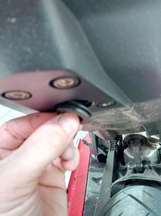
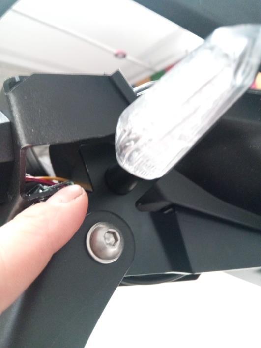
6 ISTRUZIONI DI MONTAGGIO ITALIANO 1) Utilizzando le chiavi, aprire e staccare il sellino passeggero. 2) Svitare le 4 viti del portatarga di serie. 3) Staccare il portatarga di serie sconnettendo il cablaggio. 4) Reinserire il passacavo nella sua sede. 5) Inserire le clips M5 nel support del faretto, vedi immagini. 6) Inserire il faretto nel relativo support in lamiera. 7-8) Serrare i dadi del faretto, tagliare e inserire il profilo in gomma ad U sui bordi della lamiera. 9-10) Posizionare il componente in lamiera sul codino della moto ed avvitare il tutto tramite le viti M6 (segui disegno tecnico) ) Posizionare il supporto faretto come da immagine ed avvitare le viti M5, agire sulla regolazione ad asola come opportuno in modo da appoggiare il portatarga al codino della moto ) Inserire la spina cilindrica diametro 3 fornita come in figura e posizionare la parte del portatarga in materiale plastico. 15) Accoppiare la parte mobile del portatarga al supporto in lamiera. Prestare attenzione a inserire la spina cilindrica che bloccherà la posizione del portatarga a 30 rispetto alla verticale sul terreno, nel rispetto della normatva del codice della strada. Serrare la viteria seguendo il disegno tecnico. 16) Nel caso di utilizzo del kit con indicatori di direzione, questi ultimo vanno applicati come da immagine. Inserire il nuovo cablaggio elettrico nel foro di passaggio e fissarlo utilizzando delle fascette da elettricista. Ripristinare le connessioni elettriche seguendo le illustrazioni in coda, adagiare i cablaggi in modo da evitare vibrazioni e controllare il corretto funzionamento dei dispositivi luminosi. 17) Montare il sellino passeggero. ENGLISH 1) Using the keys, open and detach the passenger seat. 2) Unscrew the 4 screws of the standard license plate holder. 3) Remove the standard number plate holder disconnecting the wiring. 4) Put the fairlead in its position. 5) Insert the M5 clips into the light support, see pictures. 6) Insert the rear light we supply in the relevant sheet support. 7-8) Tighten the light nuts, cut and insert the "U" rubber profile on the edges of the bracket. 9-10) Place the metal component on the tail of the motorcycle and screw all using the M6 screws (follow technical drawing).
 Insert the cylindrical pin supplied (diameter 3mm) as shown in the figure and place the plastic component of your plate holder.")

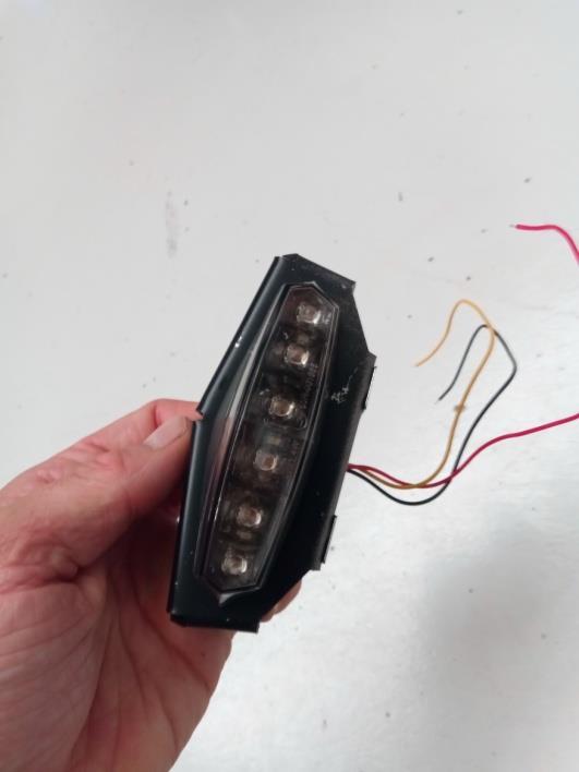
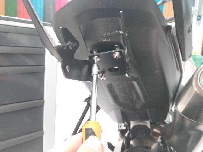
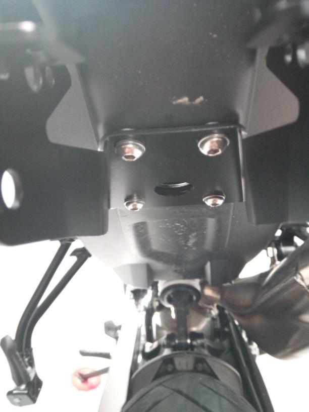
7 11-12) Place the light support as shown in the picture and tighten the M5 screws, act on the hole adjustment as appropriate as you think in order to place the plate holder to the tail of the bike ) Insert the cylindrical pin supplied (diameter 3mm) as shown in the figure and place the plastic component of your plate holder. 15) Match the movable part of the plate holder to the metal support. Pay attention to correctly insert the cylindrical pin which will block the position of the number plate holder at 30, respecting the road code law. Tighten the screws according to the technical drawing. 16) If the kit is used with indicators lights, these must be fit as shown in the picture. Insert the new electrical wiring in the proper hole and fix it using some plastic ties. Refresh the electrical connections following the illustrations as follow. Place the wiring in order to avoid vibrations and check the correct functioning of the lighting devices. 17) Mount the passenger seat. CONNESSIONE ELETTRICA 1CABLAGGIO DI SERIE/ORIGINAL WIRING

8 PER FARETTO ELT-015 / IN CASE OF ELT-015 LIGHT TABELLA COLORI CAVI CABLAGGIO DI SERIE WIRE COLORS ORIGINAL WIRING CABLAGGIO DI SERIE FILO GIALLO: stop FILO MARRONE: massa FILO BIANCO: posizione ORIGINAL LIGHT WIRING YELLOW WIRE: brake BROWN WIRE: mas WHITE WIRE: position CABLAGGIO PORTATARGA EVOTECH Filo rosso faretto Filo nero faretto+filo nero luce targa Filo giallo faretto+ filo rosso luce targa EVOTECH LIGHT WIRING Red wire for the rear light Black wire of rear light+ black cable of evotech led light Yellow cable of rear light + red cable of led light TABELLA COLORI CAVI CABLAGGIO CON CONNETTORE EVOTECH CN-001 (OPTIONAL) WIRE COLORS USING EVOTECH WIRING CN-001 (SOLD SEPARATELY) CONNETTORE EVOTECH CN-001 (VENDUTO SEPARATAMENTE) FILO MARRONE: stop FILO NERO: massa FILO BLU: posizione CONNECTOR EVOTECH CN-001 (SOLD SEPARATELY) BROWN WIRE: brake BLACK WIRE: mas BLUE WIRE: position CABLAGGIO PORTATARGA EVOTECH Filo rosso faretto Filo nero faretto+filo nero luce targa Filo giallo faretto+ filo rosso luce targa EVOTECH LIGHT WIRING Red wire for the rear light Black wire of rear light+ black cable of evotech led light Yellow cable of rear light + red cable of led light

9 PER FARETTO ELT-006 / IN CASE OF ELT-006 LIGHT TABELLA COLORI CAVI CABLAGGIO DI SERIE WIRE COLORS ORIGINAL WIRING CABLAGGIO DI SERIE FILO GIALLO: stop FILO MARRONE: massa FILO BIANCO: posizione ORIGINAL LIGHT WIRING YELLOW WIRE: brake BROWN WIRE: mas WHITE WIRE: position CABLAGGIO PORTATARGA EVOTECH Filo verde faretto Filo nero faretto+filo nero luce targa Filo giallo faretto+ filo rosso luce targa EVOTECH LIGHT WIRING Green wire for the rear light Black wire of rear light+ black cable of evotech led light Yellow cable of rear light + red cable of led light TABELLA COLORI CAVI CABLAGGIO CON CONNETTORE EVOTECH CN-001 (OPTIONAL) WIRE COLORS USING EVOTECH WIRING CN-001 (SOLD SEPARATELY) CONNETTORE EVOTECH CN-001 (VENDUTO SEPARATAMENTE) FILO MARRONE: stop FILO NERO: massa FILO BLU: posizione CONNECTOR EVOTECH CN-001 (SOLD SEPARATELY) BROWN WIRE: brake BLACK WIRE: mas BLUE WIRE: position CABLAGGIO PORTATARGA EVOTECH Filo verde faretto Filo nero faretto+filo nero luce targa Filo giallo faretto+ filo rosso luce targa EVOTECH LIGHT WIRING Green wire for the rear light Black wire of rear light+ black cable of evotech led light Yellow cable of rear light + red cable of led light
ESTR ESTR-0709 Portatarga regolabile per Triumph Speed Triple S (2016)
") ESTR-0709 ESTR-0709 Portatarga regolabile per Triumph Speed Triple S (2016) Attenzione: Prima di procedere alla seguente descrizione di montaggio, Evotech specifica che declina all utente le responsabilità
ESTR-0709 ESTR-0709 Portatarga regolabile per Triumph Speed Triple S (2016) Attenzione: Prima di procedere alla seguente descrizione di montaggio, Evotech specifica che declina all utente le responsabilità
ESTR ESTR-1106 Portatarga regolabile per BMW R1200 (2015) 2 posizioni frecce per compatibilità con borse turismo.
 2 posizioni frecce per compatibilità con borse turismo.") ESTR-1106 ESTR-1106 Portatarga regolabile per BMW R1200 (2015) 2 posizioni frecce per compatibilità con borse turismo. Attenzione: Prima di procedere alla seguente descrizione di montaggio, Evotech specifica
ESTR-1106 ESTR-1106 Portatarga regolabile per BMW R1200 (2015) 2 posizioni frecce per compatibilità con borse turismo. Attenzione: Prima di procedere alla seguente descrizione di montaggio, Evotech specifica
ASSEMBLING INSTRUCTION LICENSE PLATE HOLDER CBR 1000 RR 2010
 ASSEMBLING INSTRUCTION LICENSE PLATE HOLDER CBR 1000 RR 2010 IT- Prima di procedere alla seguente descrizione di montaggio, Evotech specifica che declina all utente le responsabilità dovute ad un non corretto
Caution: Before proceeding with the assembling of the product, Evotech specifies that the user is liable for any incorrect installation of the
 ESTR-1103 BMW C-600 sport anno 2012 Utilizzabile con maniglie passeggero e non compromette il funzionamento del vano casco sottosella, con protezione antiscasso per il vano portaoggetti. Attenzione: Prima
ISTRUZIONI MONTAGGIO KIT PORTATARGA HONDA CBR 1000 RR 08 ESTR- 0111
 ISTRUZIONI MONTAGGIO KIT PORTATARGA HONDA CBR 1000 RR 08 ESTR- 0111 IT- Prima di procedere alla seguente descrizione di montaggio, Evotech specifica che declina all utente le responsabilità dovute ad un
Istruzioni di montaggio per ECOFLEX KIT Assembling Instructions for ECOFLEX KIT
 Page 1/7 Release 2 ECOFLEX Kit Istruzioni di montaggio per ECOFLEX KIT Assembling Instructions for ECOFLEX KIT Prima di effettuare le varie operazioni procedere nel modo seguente: - Portare la macchina
NOTE DI ASSEMBLAGGIO ASSEMBLY NOTE pag. 1/5 Y102 YAMAHA MT x1
 NOTE DI ASSEMBLAGGIO ASSEMBLY NOTE pag. 1/5 ATTENZIONE: Questo impianto di scarico, codice: Y102090CV / Y102090TV, è omologato per l utilizzo stradale, SOLAMENTE con l istallazione del catalizzatore, codice:
NOTE DI ASSEMBLAGGIO ASSEMBLY NOTE pag. 1/5 Y104 YAMAHA MT x1
 NOTE DI ASSEMBLAGGIO ASSEMBLY NOTE pag. 1/5 ATTENZIONE: Questo impianto di scarico, codice: Y104090CV / Y104090TV, è omologato per l utilizzo stradale, SOLAMENTE con l istallazione del catalizzatore, codice:
NOTE DI ASSEMBLAGGIO ASSEMBLY NOTE pag. 1/5 H131 Honda CB 650 F 2014 KIT
 NOTE DI ASSEMBLAGGIO ASSEMBLY NOTE pag. 1/5 ATTENZIONE: Questo impianto di scarico, codice: H131090IV / H131090TV, è omologato per l utilizzo stradale SOLAMENTE con l istallazione del catalizzatore codice:
SOSTITUZIONE MOTORE LECOASPIRA (escluso modelli FAV) LECOASPIRA MOTOR REPLACEMENT (except FAV) 01/03/16 v.01
 LECOASPIRA MOTOR REPLACEMENT (except FAV) 01/03/16 v.01") SOSTITUZIONE MOTORE LECOASPIRA (escluso modelli FAV) LECOASPIRA MOTOR REPLACEMENT (except FAV) 01/03/16 v.01 OGGETTO DELLA PROCEDURA PROCEDURE OBJECT 2 Per tutti i Lecoaspira (esclusi i nuovi FAV20/30/50/70/80)
SOSTITUZIONE MOTORE LECOASPIRA (escluso modelli FAV) LECOASPIRA MOTOR REPLACEMENT (except FAV) 01/03/16 v.01 OGGETTO DELLA PROCEDURA PROCEDURE OBJECT 2 Per tutti i Lecoaspira (esclusi i nuovi FAV20/30/50/70/80)
NOTE DI ASSEMBLAGGIO ASSEMBLY NOTE pag. 1/6 Y102 YAMAHA MT 09 Tracer 2015 KIT
 NOTE DI ASSEMBLAGGIO ASSEMBLY NOTE pag. 1/6 A C B D SMONTAGGIO DELLA PEDANA CENTRALE DI SERIE Svitare i due bulloni supporto cavalletto centrale, sul lato destro e sinistro della moto (Fig. A,B); Rimuovere
EVOTECH
 http://www.evotech-rc.it/ EVOTECH Trentino Seguici anche su https://www.facebook.com/evotechsrl/?fref=ts https://www.youtube.com/user/evotechitaly www.twitter.com/evotechitaly1 http://www.pinterest.com/evotechitaly/
ATTENZIONE! / WARNING! Scollegare le batterie prima di qualsiasi operazione! Disconnect batteries before servicing! Kit caricabatteria :
 Page 1 / 8 Release INSTALLATION INSTRUCTIONS PROCEDURA D INSTALLAZIONE 1 3 ATTENZIONE! / WARNING! Scollegare le batterie prima di qualsiasi operazione! Disconnect batteries before servicing! Kit caricabatteria
User Manual. Rev Date: 31/05/2018
 Size / Misure 8 50 500 60 150 POWER IN DMX IN DMX OUT 9 4. POWER+DMX out cable + M8 Female Connector 16,80 Connection kit included with the Startline cable / Kit di connessione compreso alla startline
ASSEMBLY NOTE pag.1/6
 ASSEMBLY NOTE pag.1/6 A B Final body no CAT C D DISMOUNTING THE ORIGINAL Disassemble the original silencer (Fig. A), removing the screw of the crank (Fig.B) and loosening the small metal bracket, which
Pagina 2 di 9 A - OGGETTO A - OBJECT B - SCOPO B - SCOPE. Instruction Sheet Rev. A
 COMPARTMENT A - OBJECT Wired fuse and relay box for engine compartment (P/N 1745062). Base box supply with sealing and spacer rings assembled whereas cover is in kit into same packaging. Base box have
Istruzioni di montaggio per l ECOFLEX KIT Assembling Instructions for ECOFLEX KIT
 Page 1/7 Release 4 ECOFLEX SYSTEM Istruzioni di montaggio per l ECOFLEX KIT Assembling Instructions for ECOFLEX KIT Prima di effettuare le varie operazioni procedere nel modo seguente: - Portare la macchina
Kit Retrofit Electronic Timer Cod
 Kit Retrofit Electronic Timer Cod. 060769 00 The Kit Retrofit Electronic Timer includes: Electronic Timer Part Number 620507 01 Wiring Diagrams Electrical harness with 8 contacts connector and two 3 contacts
RETROFIT KIT KONE - KRM - KCEAPM - KONEXION
 RETROFIT KIT KONE - KRM - KCEAPM - KONEXION 7IS-80416 30/01/2019 COMPONENTI / COMPONENTS Helpy 2W-V 12V MK (5HL-006) Cavo per kit retrofit Kone / Cable retrofit kit Kone (5KT-120) INSTALLAZIONE KRM / KRM
INSTALLATION GUIDE ITA-ENG PLATE HOLDER DUCATI PANIGALE V4
 INSTALLATION GUIDE ITA-ENG PLATE HOLDER DUCATI PANIGALE V4 C o d e : D 1 8 2 P T w w w. t e r m i g n o n i. c o m L i s t a componenti P a c k i n g l i s t D182PT DUCATI PANIGALE V4 Plate Holder 1 2
NOTE DI ASSEMBLAGGIO / ASSEMBLY NOTE pag. 1/5. K063 Kawasaki ER-6N 10 1 Sil
 AA NOTE DI ASSEMBLAGGIO / ASSEMBLY NOTE pag. 1/5 AB SMONTAGGIO DEL SILENZIATORE ORIGINALE AC AD Smontare il carter in plastica della fiancata (Fig. AA e AB); Smontare la pancia rimuovendo le quattro viti
ASSEMBLY NOTE / SCHEDA DI MONTAGGIO pag.1/9 D155 Ducati Panigale 1299 Coppia sil.
 ASSEMBLY NOTE / SCHEDA DI MONTAGGIO pag.1/9 D155 Ducati Panigale 1299 Coppia sil. 01 02 03 04 05 06 SMONTAGGIO IMPIANTO ORIGINALE Rimuovere le carene inferiori destra e sinistra della moto, svitando le
Emulatore pressione benzina per Volvo. Petrol pressure emulator for Volvo vehicles. Cod. AEB431
 Emulatore pressione benzina per Volvo Petrol pressure emulator for Volvo vehicles Cod. AEB431 Manuale Istruzioni di Montaggio Assembly Instruction Manual Via dell Industria, 20 (Zona Industriale Corte
ERGO ERGO. Istruzioni per il cablaggio Wiring instructions. // Istruzioni per il montaggio // Assembly instructions
 ERGO Istruzioni per il cablaggio Wiring instructions 64W ON/OFF MARRONE / BROWN - Linea / line GIALLO-VERDE / YELLOW-GREEN - Terra / Earth ERGO 65 BLU / BLUE - Neutro / Neutral // Istruzioni per il montaggio
KIT AMMORTIZZATORE DI STERZO
 KIT AMMORTIZZATORE DI STERZO Codice: KIT032 Marca: BUELL Modello: X1 LIGHTNING MATERIALE CONTENUTO NEL KIT - n 1 Attacco forcella d.54 - n 2 Vite Tcei M5x12 - n 1 Vite in ergal M8x25 - n 2 OR - n 1 Ammortizzatore
UNA. Istruzioni di montaggio / Installation instructions
 UNA Istruzioni di montaggio / Installation instructions UNA Istruzioni per il montaggio dei lavabi semincasso art. UNA75L e art. UNA90L Installation instructions of semi-inset basins art. UNA75L and art.
ASSEMBLY NOTE / SCHEDA DI MONTAGGIO pag.1/5 D155 Ducati Panigale 1299 Coppia sil.
 ASSEMBLY NOTE / SCHEDA DI MONTAGGIO pag.1/5 01 02 03 04 05 06 SMONTAGGIO IMPIANTO ORIGINALE Rimuovere le carene inferiori destra e sinistra della moto, svitando le viti di supporto (Fig. 01, 02); Rimuovere
NOTE DI ASSEMBLAGGIO ASSEMBLY NOTE pag. 1/6 H129 Honda CRF 250 R 2015 Kit
 NOTE DI ASSEMBLAGGIO ASSEMBLY NOTE pag. 1/6 A B SMONTAGGIO DEL SILENZIATORE ORIGINALE Svitare le viti della sella e delle fiancatine (Fig. A,B,C); Rimuovere la sella per poi rimuovere le fiancatine (Fig.
sensori per cilindri magnetic sensors for cylinders
 Schema di collegamento: fili Wiring diagram: wires Modello Model RS1-A RS-A RS5-C RS-A RS-A Funzione Function Reed NC Reed NC Numero fili Number of wires Lunghezza cavo Lenght of wires Connettore Connector
ERGO. Istruzioni per il cablaggio // Wiring instructions. // Istruzioni per il montaggio // Assembly instructions
 Istruzioni per il cablaggio // Wiring instructions 64W ON/OFF ERGO IP 65 // Istruzioni per il montaggio // Assembly instructions 125W / 252W ON/OFF (Doppia accensione) // ON/OFF (Double switching) DALI
IM095.1 ISTRUZIONI DI MONTAGGIO ASSEMBLY DIAGRAM > LINK SYSTEM SOSPESO ED ELEMENTO TERMINALE APERTO > HANGING LINK SYSTEM AND OPEN END ELEMENT
 ISTRUZIONI DI MONTAGGIO > LINK SYSTEM SOSPESO ED ELEMENTO TERMINALE APERTO ASSEMBLY DIAGRAM > HANGING LINK SYSTEM AND OPEN END ELEMENT HANGING LINK SYSTEM AND OPEN END ELEMENT: Identificare la posizione
FIRENZE professional grinders. Manuale Tecnico. Troubleshooting. MIGNON Capitolo IV.
 FIRENZE 1920 professional grinders Manuale Tecnico Troubleshooting Capitolo IV www.eureka.co.it guida alla soluzione dei problemi - trouble shooting 1 Regolazione Macinatura Grinding Adjustment 2 Sostituzione
Interface A25 (+90 ) Interfaccia A25 (+90 ) O-RING #109 O-RING #109 O-RING #010 O-RING #109
 Interfaccia A25 (+90 ) O-RING #109 O-RING #109 O-RING #010 O-RING #109") Accessori Gimapick Gimapick Accessories A25 Interfaccia A25 (+90 ) L interfaccia A25 è necessaria quando l asse di rotazione e/o di presa debba essere posto a 90 rispetto all asse di traslazione o rispetto
Accessori Gimapick Gimapick Accessories A25 Interfaccia A25 (+90 ) L interfaccia A25 è necessaria quando l asse di rotazione e/o di presa debba essere posto a 90 rispetto all asse di traslazione o rispetto
SonDa acqua SanitaRia
 SonDa acqua SanitaRia IT avvertenze PrelIMINarI questa istruzione è parte integrante del libretto dell apparecchio sul quale viene installato il Kit. a tale libretto si rimanda per le avvertenze GEnERaLi
WARNING! Scollegare le batterie prima di qualsiasi operazione! Disconnect the batteries before servicing! INSTALLATION INSTRUCTIONS
 Page 1 / Release 1 vacuum kit 146 2524 000 INSTALLATION PROCEDURE PROCEDURA D INSTALLAZIONE 1 4 5 11 2 3 6 7 9 10 WARNING! Scollegare le batterie prima di qualsiasi operazione! Disconnect the batteries
NOTE DI ASSEMBLAGGIO ASSEMBLY NOTE pag. 1/5 T009 TRIUMPH STREET TWIN 1 SIL.
 NOTE DI ASSEMBLAGGIO ASSEMBLY NOTE pag. 1/5 01 03 02 04 05 06 07 08 SMONTAGGIO DEL SILENZIATORE ORIGINALE Rimuovere il paracalore svitando la vite di sostegno (Fig. 01); Rimuovere la fascetta innesto silenziatore,
sensori per cilindri magnetic sensors for cylinders Schema di collegamento: 2 fili Wiring diagram: 2 wires RS2-A RS1-A RS3-A RS4-A RS5-C Modello Model
 Schema di collegamento: fili Wiring diagram: wires Modello Model RS1-A RS-A RS5-C RS-A RS4-A Funzione Function Reed NC Reed NC Numero fili Number of wires Lunghezza cavo Length of wires Connettore Connector
ISTRUZIONI PER IL MONTAGGIO DEL KIT SSD INSTRUCTIONS TO INSTALL THE KIT SSD
 Audya Series ISTRUZIONI PER IL MONTAGGIO DEL KIT SSD INSTRUCTIONS TO INSTALL THE KIT SSD ISTRUZIONI PER L APERTURA DI AUDYA (FIG. 1) 1. Svitare le 4 viti poste sul fondo 2. Svitare le 2 viti poste
ASSEMBLY NOTE / SCHEDA DI MONTAGGIO pag.1/5 D155Y2 Ducati Panigale 959 Forcella
 ASSEMBLY NOTE / SCHEDA DI MONTAGGIO pag.1/5 01 02 03 04 SMONTAGGIO IMPIANTO ORIGINALE Rimuovere le carene inferiori destra e sinistra della moto, svitando le viti di supporto (Fig. 01, 02); Allentare la
BT-0208 BLOCCHETTI TENDICATENA YAMAHA R YAMAHA R CHAIN ADJUSTER
 BT-0208 BLOCCHETTI TENDICATENA YAMAHA R6 2009-12 YAMAHA R6 2009-12 CHAIN ADJUSTER Attenzione: Prima di procedere alla seguente descrizione di montaggio, Evotech specifica che declina all utente le responsabilità
SonDa cascata. avvertenze PrelIMINarI. CoNTeNUTo. UTeNSIlI CoNSIGlIaTI. NexPolar
 SonDa cascata IT avvertenze PrelIMINarI Questa istruzione è parte integrante del libretto dell apparecchio sul quale viene installato il KIt. a tale libretto si rimanda per le avvertenze GEnERaLI e per
PORTA DA INTERNO FILO MURO BATTENTE
 PORTA DA INTERNO FILO MURO BATTENTE ISTRUZIONI DI MONTAGGIO installation instructions 7 9 8 6 5 4 TELAIO REVERSIBILE reversible frame 180 1 ANTA REVERSIBILE reversible panel 2 3 1 - Pannello - panel 2
series Contatore volumetrico ultrasonico DN 125 / DN 150 / DN 200 Ultrasonic flow meter DN 125 / DN 150 / DN 200 H I EN
 H0001071 www.caleffi.com Contatore volumetrico ultrasonico DN 125 / DN 150 / DN 200 Ultrasonic flow meter DN 125 / DN 150 / DN 200 I EN Copyright 2016 Caleffi 7557 series Funzione Function Il contatore
Per un corretto montaggio For correct assembling
 LINE cquario Serie composta da interruttori, prese, una presa tipo Schuko ed una presa standard francese. Vanno abbinati alle rispettive cornici da ordinare a parte. Le cornici, di forma ondulata o rotonda,
Mandrino automatico porta-pinze da barra Power operated collet chuck for bar machining. Attacco cilindrico - Plain back mounting
 Mandrini porta-pinze da barra serie PPBE Collet chucks for bar machining PPBE series PPBE Mandrino automatico porta-pinze da barra Power operated collet chuck for bar machining Attacco cilindrico - Plain
ISTRUZIONI MONTAGGIO PORTATARGA MONSTER
 ISTRUZIONI MONTGGIO PORTTRG MONSTER 1100 2009 Prima di procedere alla seguente descrizione di montaggio, Evotech specifica che declina all utente le responsabilità dovute ad un non corretto montaggio dei
Pozzetto per rullo scherma
 ITALIANO Pozzetto per rullo scherma In pochi secondi il rullo può essere estratto e bloccato sopra il coperchio del pozzetto oppure reinserito nello stesso, lasciando libero il pavimento per altre attività.
ST CLS. Manuale di installazione ed uso. Figura 1 LINGUA ITALIANO COLONNA PER BARRIERE LS
 Manuale di installazione ed uso LINGUA ITALIANO Il presente foglio tecnico illustra le operazioni necessarie per: Il corretto montaggio delle barriere, LS all interno delle colonne per fissaggio a pavimento.
INSTALLATION GUIDE ITA-ENG COMPLETE SYSTEM
 INSTALLATION GUIDE ITA-ENG COMPLETE SYSTEM O N L Y F O R R A C E U S E DUCATI MULTISTRADA 950 C o d e : D 1 6 8 0 9 4 4 0 I T A w w w. t e r m i g n o n i. c o m L i s ta c o m p o n e n t i P a c k i
Accessori Accessories
 e order number 6000086MH 6000085MM 6000091MA 6000090MA 6000114MA 6000089MA 6000106MA 6000113MA 604001100 604004900 600012700 600013700 600013600 600012500 600030600 600012600 600018200 600022400 600024200
INSTALLATION GUIDE ITA-ENG COLLECTOR
 INSTALLATION GUIDE ITA-ENG COLLECTOR O N L Y F O R R A C E U S E HONDA X-ADV C o d e : H 1 4 2 0 9 4 1 0 I X X w w w. t e r m i g n o n i. c o m L i s t a c o m p o n e n t i P a c k i n g l i s t 1 2
Libretto uso e manutenzione. Owner s handbook. rev /07
 Libretto uso e manutenzione Owner s handbook Elenco componenti List of components ALBERTO SASSI S.p.A. www.sassi.it 2 ALBERTO SASSI S.p.A. www.sassi.it 3 ALBERTO SASSI S.p.A. www.sassi.it 4 Tabella riferimento
KIT AMMORTIZZATORE STERZO
 N. DI MATRICOLA/SERIAL N. KIT 024 DA INDICARE IN CASO DI RECLAMO/ TO BE MENTIONATED IN CASE OF CLAIM KIT AMMORTIZZATORE STERZO Tutte le operazioni di smontaggio e montaggio contenute in questo manuale
BX-6M BX-6M- AS Apparecchiatura elettronica SCHEMA ELETTRICO E COLLEGAMENTI. Electronic control unit ELECTRICAL CONNECTIONS
 BX-6M BX-6M- AS07010 Apparecchiatura elettronica SCHEMA ELETTRICO E COLLEGAMENTI Electronic control unit ELECTRICAL CONNECTIONS I UK 2 BX-6M I UK ŸQuesto prodotto è stato collaudato da GI.BI.DI., verificando
KIT AMMORTIZZATORE STERZO
 N. DI MATRICOLA / SERIAL N. KIT 140 DA INDICARE IN CASO DI RECLAMO/ TO BE MENTIONATED IN CASE OF CLAME/ KIT AMMORTIZZATORE STERZO Tutte le operazioni di smontaggio e montaggio contenute in questo manuale
EQC. DAQC / DCQC (opzionali) DAQC / DCQC (optional) 16.4
 DAQC / DCQC (optional) 16.4") DAQC / DCQC (opzionali) Moduli di alimentazione remota 5 connessioni elettriche Contatti con pin a tasteggio autopulenti Le due parti sono fornite separatamente: DAQC - lato robot DCQC - lato telaio DAQC
DAQC / DCQC (opzionali) Moduli di alimentazione remota 5 connessioni elettriche Contatti con pin a tasteggio autopulenti Le due parti sono fornite separatamente: DAQC - lato robot DCQC - lato telaio DAQC
Contents of Kit Contenuto del Kit
 Page 1 / 6 Release 4 Installation Instructions/ Istruzioni di Montaggio KIT CARICA BATTERIA 146 2052 000-230V / / 146 2823 000-115V Contents of Kit Contenuto del Kit Page 2 / 6 Release 4 ITEM/ Pos. QTY/
SCHEDA INSTALLAZIONE / INSTALLATION CARD VORTEX CUBE ERT
 SCHEDA INSTALLAZIONE / INSTALLATION CARD VORTEX CUBE ERT Modello CUBE, versione ERT con tubo di Modello collegamento di CUBO da 0.5m. con display, versione ERT con tubo di collegamento da 0.5m. CUBE Cube
Istruzioni Montaggio Mounting Instructions
 Istruzioni Montaggio Mounting Instructions FURIOUS Easy con Connettori per FAZUA (Pinarello NYTRO) Rimuovere il gruppo MOTORE-BATTERIA dall E-BIKE Remove the ENGINE-BATTERY group from the E-BIKE Alcuni
ISTRUZIONI DI MONTAGGIO / OPERATION INSTRUCTION
 ISTRUZIOI DI MOTAGGIO / OPERATIO ISTRUCTIO BOIE e CYDE lampada a sospensione / hanging lamp B01; C01; B11; C11; B21; C21 A) installazione e la manutenzione va eseguita ad apparecchio spento. Tutte le operazioni
Istruzioni per il montaggio del kit codice 8000 A4843 sul gruppo avviamento a pedale dei motocicli TE 510, TE-TC- SMR 450, TE-TC 250 Assembling
 Istruzioni per il montaggio del kit codice 8000 A4843 sul gruppo avviamento a pedale dei motocicli TE 510, TE-TC- SMR 450, TE-TC 250 Assembling instructions for kit code no. 8000 A4843 on kick starter
HERMITAGE ISTRUZIONI DI MONTAGGIO ASSEMBLY INSTRUCTIONS
 U Via Monsignor Tenderini snc 01033 Civita Castellana (Vt) - Italy t. (+39) 0761 599499 f. (+39) 0761 514232 e. INFO@RTCERM.IT w. WWW.RTCERM.IT E E1 G D1 D B D1 1 Girare la vasca sottosopra e fissare con
king license plate holder portatarga king
 king license plate holder portatarga king 74 bike model year code SUZUKI GSXS1000 15-16 PRTR001 YAMAHA MT07 14-16 PRTR002 MT09 13-16 PRTR003 KAWASAKI Z800 13-16 PRTR004 Z1000 14-16 PRTR005 characteristics
Scheda tecnica - Specifications. Sicurezza - Safety
 MANHATTAN Istruzioni Assembly instructions Leggere attentamente le istruzioni e conservarle per un utilizzo futuro Read this instruction sheet carefully and keep it for future reference A B C mm.15 G D
CLIP PER FISSAGGIO RAPIDO DEL BINARIO TRACK FAST FIXING BRACKET
 S-9000/115-B S-9000/115-W CLIP PER FISSAGGIO RAPIDO DEL BINARIO TRACK FAST FIXING BRACKET Dati tecnici Technical data Caratteristiche Characteristics Clip In acciaio verniciato Bracket in painted steel
RETROFIT KIT KONE - KRM - KCEAPM - KONEXION
 RETROFIT KIT KONE - KRM - KCEAPM - KONEXION 7IS-80416 14/03/2019 COMPONENTI / COMPONENTS Helpy 2W-V 12V MK (5HL-006) Cavo per kit retrofit Kone / Cable retrofit kit Kone (5KT-120) INSTALLAZIONE KRM / KRM
SACE Emax Operazioni preliminari - Preliminary Operations. 2 - Verifica contenuto kit - Kit content verify 1 OK 2 OK
 Doc. N SDH00400R090 - ECN0000674 - Rev. B SACE Emax Kit Morsettiera - E.-E4.-E6. Kit Klemmleiste - E.-E4.-E6. Kit Terminal Box - E.-E4.-E6. Kit Bornier - E.-E4.-E6. Kit Regleta De Bornes - E.-E4.-E6. -
INSTALLATION INSTRUCTION Date REL. Description Part No /02/02 0 Installation instruction for Electronic board KIT Page 1 /
 Page 1 / 5 08812882 KIT COMPONENTS / COMPONENTI DEL KIT a) electronic board / scheda elettronica b) support bracket / staffa di supporto c) n 2 electromagnetic switchs / teleruttori d) n 6 screws M4 hexagonal
DISPOSITIVO DI COMANDO PROPORZIONALE AIR PROPORTIONAL CAB SWITCH
 DISPOSITIVO DI COMANDO PROPORZIONALE AIR PROPORTIONAL CAB SWITCH CODICE FAMIGLIA FAMILY CODE SERIE SERIES 100 Codice fascicolo: 997-400-00075 Dispositivo di comando pneumatico proporzionale a cloche per
DIESEL& PETROL ENGINE ISTRUZIONI DI MONTAGGIO INSTALLATION MANUAL. CPBX STD rev
 P R O G R A M M A B L E DIESEL& PETROL C H I P T U N I N G U N I T ENGINE ISTRUZIONI DI MONTAGGIO INSTALLATION MANUAL CPBX STD rev 1.0 2018 06 AVVERTENZE / WARNINGS 1 LEGGI QUESTA GUIDA CON ATTENZIONE
- - Istruzioni per l installazione Installation guide
 - - Istruzioni per l installazione Installation guide KETRON X4 & XD3 Istruzioni per l apertura dello strumento Instructions to open the instrument - Togliere le 6 viti. Remove the 6 screws. - Togliere
controlli di livello capacitivi capacitive levels controls
 controlli di livello capacitivi capacitive levels controls SENSORI CAPACITIVI ALTA TEMPERATURA SC18M-HT/SC30M-HT HIGH TEMPERATURE CAPACITIVE SENSORS SC18M-HT/SC30M-HT MODELS GENERALITÀ GENERAL DETAILS
Outdoor wireless wall switch
 www.trust.com SECURITY PLUS-LINE AGST-8800 USER MANUAL MULTI LANGUAGE Item 71151 Version 1.0 Visit www.trust.com for the latest instructions Outdoor wireless wall switch 1 2 3 OFF OFF OFF OFF ON + ON ON
SACE Emax 2. 1 - Operazioni preliminari - Preliminary Operations. 2 - Verifica contenuto kit - Kit content verify C X8 B D X4.
 Doc. N 1SDH001399R0932 - L9679 SAE Emax 2 Guide Laterali Parte Mobile - E1.2 Lateral Guides Moving Part - E1.2 Seitenbleche - E1.2 Plaques Laterales - E1.2 Laterales - E1.2 1 - Operazioni preliminari -
ART. 1254AL155SS CERNIERE PER PORTE A SPINGERE MANO SINISTRA / HINGES FOR LEFT-HAND DOORS
 SCHEDA INSTALLAZIONE / INSTALLATION SHEET ART. 1254AL155DS CERNIERE PER PORTE A SPINGERE MANO DESTRA / HINGES FOR RIGHT-HAND DOORS UPPER HINGE BODY SACCHETTO GRUPPO MOLLA / PLASTIC BAG WITH THE SPRING
INSTALLATION GUIDE ITA-ENG CATALYZER YAMAHA T-MAX
 INSTALLATION GUIDE ITA-ENG C o d e : Y 1 1 3 C A T w w w. t e r m i g n o n i. c o m Y113CAT L i s ta c o m p o n e n t i P a c k i n g l i s t 2 w w w. t e r m i g n o n i. c o m Y113CAT L i s ta c o
istruzioni di montaggio - manutenzione BUBBLE UP 300 MIN 160 MIN 160
 istruzioni di montaggio - manutenzione prodotto rispondente ai requisiti previsti dalle Direttive Comunitarie Europee NOTA BENE: le presenti istruzioni di montaggio informano l utilizzatore sulle corrette
MANUALE OPERATIVO / INSTRUCTION MANUAL IM200-IU v1.3 CT / CTD CT / CTD. Toroidal current transformers. Trasformatori di corrente toroidali. pag.
 MANUALE OPERATIVO / INSTRUCTION MANUAL IM200-IU v1.3 CT / CTD Trasformatori di corrente toroidali CT / CTD Toroidal current transformers pag. 1 / 5 ATTENZIONE!!! Leggere attentamente il manuale prima dell
SRT064 BTH SRT051 BTH SRT052 BTH
 KIT FOR TRUCK BRAKE TESTERS SRT051 BTH SRT052 BTH OPERATOR S MANUAL SRT064BTH SRT051BTH SRT052BTH CONTENTS 1. INTRODUCTION...1 2. Description of SRT064BTH Kit...2 3. Description of SRT051BTH Kit...2 4.
6 POSITIONS SEALED CONNECTOR FOR MICRO TIMER II CONTACT
 Instruction Sheet 411-20068 6 POSITIONS SEALED CONNECTOR FOR MICRO TIMER II CONTACT A-OBJECT 6 positions connector P/N 284716 in all configurations and versions. B-SCOPE To provide useful information for
FIAT DUCATO. Ampliamento impianto di condizionamento per veicoli con:
 FIAT DUCATO Ampliamento impianto di condizionamento per veicoli con: - Impianto cabina originale predisposto per collegamento 2 evaporatore (cod. 12121583) - Impianto cabina originale non predisposto per
ASSEMBLY ISTRUCTIONS SQUAT WITH FRESH WATER FLUSH
 ASSEMBLY ISTRUCTIONS SQUAT WITH FRESH WATER FLUSH ATTENTION: DO NOT USE FIVE SCREWS INSIDE OF THE KIT. DO NOT MAKE ANY HOLES IN THE TANK. ASSEMBLY ISTRUCTIONS SQUAT WITH FRESH WATER FLUSH Prepare the base
Dimensioni in millimetri. Dimensions shown in millimetres.
 MINI-DISTRIBUToRE DI CoRRENTE AD ELEVATA PRoTEzIoNE. 4 PoLI. 28 80 54 Dimensioni in millimetri. Dimensions shown in millimetres. Dati generali General data Dati tecnici Technical data N. poli 4 N. poles
Cavi Cables. Mini blocca cavi Mini cable clamp
 05 Cavi Mini blocca cavi Mini cable clamp 05 Colori Colors Bianco White Trasparente Transparent Trasparente con riga rossa Transparent with red line Trasparente con riga nera Transparent with black line
Image distorsion wheels
 ORDER DIRECTLY TODAY AT: www.bulbamerica.com or CALL TOLL FREE 888-505-2111 Foglio di Istruzioni Owner s Manual Image distorsion wheels GR0640 GR0640 Rev. 0 10 Dic 2002 ORDER DIRECTLY TODAY AT: www.bulbamerica.com
Heat cost allocators Mounting manual
 - heat cost allocators ripartitori di calore Mounting Manual Manuale di montaggio Heat cost allocators Mounting manual Ripartitori dei costi di calore - Manuale di montaggio pag. 1 Mounting the allocator
JUBE SP G-P. English. Italiano. rev. 2. ISTRUZIONI PER IL MONTAGGIO Check there is no network voltage before installing the equipment.
 JUBE SP G-P English rev. 2 Italiano ASSEMBLY INSTRUCTION ISTRUZIONI PER IL MONTAGGIO Check there is no network voltage before installing the equipment. Assicurarsi che non sia presente tensione di rete
SCHEMA DI MONTAGGIO CREDENZA SEQUENCE ASSEMBLING SHEET SIDEBOARD SEQUENCE
 SCHEMA DI MONTAGGIO CREDENZA SEQUENCE ASSEMBLING SHEET SIDEBOARD SEQUENCE 1/9 LA CREDENZA VERRA' SPEDITA AL CLIENTE CON PIEDI, RIPIANI INTERNI E ANTE SMONTATI (vedi Immagine 1). SI DOVRA' QUINDI PROCEDERE
IM118.0 ISTRUZIONI DI MONTAGGIO ASSEMBLY DIAGRAM LETTO SINGOLO A SCOMPARSA ORIZZONTALE: UNIT WITH HORIZONTAL FOLD- AWAY BED
 ISTRUZIONI DI MONTAGGIO LETTO SINGOLO A SCOMPARSA ORIZZONTALE: ASSEMBLY DIAGRAM UNIT WITH HORIZONTAL FOLD- AWAY BED livellatore / heightadjustable feet perno / pivot Iniziare con il montaggio dei livellatori
TROLLING MECCANICO MECHANICAL TROLLING VALVE
 TROLLING MECCANICO MECHANICAL TROLLING VALVE SECTION 4. Cod. 3.70.80.65 Ed. 0/00 Pag. 4.9 IRM 80 A / IRM 80 A / ZF 80 A (IRM 80 A ) ZF 80-A / IRM 80 PL / ZF 80 (IRM 80 PL ) / ZF 80- SCHEMI DI FUNZIONAMENTO
SACE Emax 2. 1 - Operazioni preliminari - Preliminary Operations. 2 - Verifica contenuto kit - Kit content verify 1 OK 2 OK
 Doc. N SDH00400R0905 - L9679 SACE Emax 2 Trip Coil - E2.2-E4.2-E6.2 - Operazioni preliminari - Preliminary Operations - Leggere attentamente il documento RH000003 prima di procedere - Assicurarsi che l
SENSORI CAPACITIVI CAPACITIVE SENSORS
 SENSORI CAPACITIVI CAPACITIVE SENSORS Copertine Aeco_cat_Generale.indd 2 SENSORI CAPACITIVI ALTA TEMPERATURA HIGH TEMPERATURE CAPACITIVE SENSORS 07/04/14 16.40 SENSORI CAPACITIVI ALTA TEMPERATURA SC18M-HT/SC30M-HT