Norme Tecniche Owner s Manual. VIDEOKIT Serie. Series VIDEOKIT Mono-familiari e Bi-familiari One Way, Two Way
|
|
|
- Camilla Spinelli
- 7 anni fa
- Visualizzazioni
Transcript
1 VIDEOKIT Serie VKK Series VIDEOKIT Monofamiliari e Bifamiliari One Way, Two Way Norme Tecniche Owner s Manual Videx Electronics SpA Via del Lavoro, 0 Monte Giberto (AP) Italy Phone + 0 Fax + 0 info@videxit Web: wwwvidexit Si raccomanda di far installare il presente dispositivo esclusivamente da personale qualificato We recommend This equipment is installed by a ompetent Electrician, Security or ommunications Engineer

2 VKK, VKKS Videokit Monofamiliare con videocitofono e telecamera bianco e nero I videokit della serie VKK fanno parte di una nuova linea che utilizza il posto esterno con design Serie 000 Il videocitofono fornito a corredo è Serie 000 in una versione espressamente progettata per questa linea di videokit L unità di ripresa ha le dimensioni di un modulo della Serie 000 ed è corredato dal relativo supporto da incasso (VKK) o superficie (VKKS) in base alla versione del kit Grazie all impiego della tecnologia a microprocessore sia nel modulo portiere elettrico unità di ripresa che nel videocitofono, i kit di questa linea offrono numerose funzioni innovative tra le quali troviamo: Segnalazioni acustiche e visive in merito al funzionamento del sistema in aiuto degli utenti diversamente abili; Possibilità di utilizzo della serratura tramite relè a contatti puliti o scarica capacitiva; Possibilità di collegare un pulsante per l apertura diretta della porta d ingresso; Possibilità di programmazione dei tempi d apertura porta e conversazione; Possibilità di collegare fino a ingressi con l ausilio di relè d asservimento Art0N; Predisposizione per il collegamento del modulo display Art0 e del lettore chiavi di prossimità standalone Art0; Possibilità di programmare il numero di squilli da un minimo di ad un massimo di ; Ingresso per chiamata di pianolocale; Possibilità di monitorare lo stato d aperturachiusura della porta tramite apposito LED presente sul videocitofono (è richiesto un conduttore addizionale dalla porta verso il videocitofono); Possibilità di programmare la funzione privacy da un minimo di minuti ad un massimo di ore; Predisposizione per il collegamento facilitato di un citofono in parallelo (max indipendentemente dal numero di videocitofoni in parallelo); Possibilità di collegare fino a videocitofoni in parallelo con funzione di intercomunicazione; Autoaccensione selettiva in caso di più ingressi; Brandeggio telecamera regolabile sia verticalmente che orizzontalmente con un escursione massima di 0º Il kit comprende: Unità di ripresa Art L unità incorpora una telecamera bianco e nero D autofocus di alta qualità, i LED d illuminazione agli infrarossi, la circuiteria di amplificazione audio e il portiere elettrico con un pulsante di chiamata; Supporto da incasso ad modulo Art (nella versione da superficie VKKS questo articolo è rimpiazzato dalla relativa scatola da superficie Art); Videocitofono Art Bianco & Nero con schermo piatto da completo di piastra di fissaggio a parete e scheda di connessione Art0; Trasformatore di alimentazione Art0K (ont DIN Moduli tipo A) VKK, VKKS One way videoki with B&W videophone and camera The VKK series is a new range of videokits that use the 000 series external door station and the 000 series videophone which is specific for this range of videokit The camera / audio unit is the size of a single 000 series module and is available in either flush (VKK) or surface (VKKS) mounting versions As a result of using microprocessor technology in the door panel and videophone, a number of additional features have been added to enhance the operation of the videokits and give greater feedback to the visitor and user Disability friendly, visual and acoustic signals from the door panel to inform the visitor of call status (call made, ringing, speak, door open) Programmable door open and conversation time Expandable to entrance panels (requires an additional relay Art0N for each entrance panel) onnections for a push to exit button Two methods of operating the electric lock: ) Dry contact relay, ) capacitor discharge circuit Facility for the connection of a codelock Art00, display module Art0, standalone proximity reader Art 0 or standalone biometric reader Art etc Programmable number of call tone rings from to a maximum of Input for local door bell push button Programmable timed privacy function from minutes to a maximum of hours Door open status LED (additional wire required from the door to the videophone) Up to videophones can be connected in parallel, all with intercommunication facility Videophones can have a maximum of two additional audio telephone handsets connected in parallel amera recall on all systems, with selective recall on systems with multiple entrances Door panel camera can be adjusted horizontally and vertically (0 degrees) The kit comprises of amera unit Art The unit includes a high quality B&W D camera with auto iris lens, infrared LEDs for illumination, audio amplifiers and one button speaker unit; Module front support with flush mounting box Art (the surface version of the kit VKKS includes the relevant surface mounting box Art); B&W videophone Art with flat screen complete with mounting plate and PB connection Art0; Power transformer Art0K boxed in Module A Type DIN BOX VKK, VKKS Videokit Monofamiliare con videocitofono e telecamera a colori VKK, VKKS One way videoki with colour videophone and camera ome i kit VKK e VKKS, ma con videocitofono a colori Art con monitor TFT da, e unità di ripresa Artcolour con telecamera a colori e LED d illuminazione ad emissione di luce bianca As VKK and VKKS but with Art colour videophone with, LD TFT monitor and colour camera unit Artcolour with white light illumination LEDs VKK/MV, VKKS/MV Videokit Monofamiliare con videocitofono+memoria e telecamera bianco e nero VKK/MV, VKKS/MV One way videokit with B&W videophone with memory and camera ome i kit VKK e VKKS, ma con videocitofono bianco e nero Art completo di memoria video ed alimentatore specifico Art0K/MV VKK, VKKS, VKK, VKKS Videokit Monofamiliare (bianco e nero o colori) più tastiera digitale ome i kit VKK, VKKS, VKK e VKKS ma con supporto da incasso a moduli Art, modulo tastiera digitale a codice standalone Art00 L utente può aprire la porta digitando l apposito codice tramite la tastiera VKXK, VKXKS, VKXK, VKXKS Videokit Monofamiliare (bianco e nero o colori) più lettore chiavi di prossimità ome i kit VKK, VKKS, VKK e VKKS ma con supporto da incasso a moduli Art, modulo lettore chiavi di prossimità standalone Art0 e chiavi di prossimità in formato card Art/ L utente può aprire la porta avvicinando la propria chiave di prossimità al lettore As VKK and VKKS but with B&W videophone Art with memory board and special power supply Art0K/MV VKK, VKKS, VKK, VKKS One way videokit (colour or B&W) plus a codelock module As VKK,VKKS, VKK and VKKS but with flush mounting box Art, standalone codelock module Art00 The user can open the door from outside by typing the relevant access code into the keypad VKXK, VKXKS, VKXK, VKXKS One way videokit (colour or B&W) plus a proximity key reader module As VKK,VKKS, VKK and VKKS but with flush mounting box Art, standalone proximity keys reader module Art0 and proximity keys card format Art/ The user can open the door from the outside by simply presenting a card/fob to the external reader VKFPK, VKFPKS, VKFPK, VKFPKS Videokit Monofamiliare (bianco e nero o colori) più lettore d impronte VKFPK, VKFPKS, VKFPK, VKXKS One way videokit (colour or B&W) plus a fingerprint reader module ome i kit VKK, VKKS, VKK e VKKS ma con supporto da incasso a moduli Art e modulo lettore d impronte standalone Art L utente può aprire la porta d ingresso utilizzando semplicemente le proprie dita Non sarà più possibile dimenticare le chiavi di casa As VKK,VKKS, VKK and VKKS but with flush mounting box Art and a standalone fingerprint reader module Art The user can open the door from the outside simply by swiping their finger on the reader No door keys, codes or fobs to forget VKK

3 VKK VKK VKK/MV VKKS VKKS VKK/MVS Flush Door Station Posto Esterno da Incasso Surface Door Station Posto Esterno da Superficie 0 0 VKK VKXK VKFPK VKK VKXK VKFPK Tutti i videokit indicati di lato sono disponibili anche in versione bifamiliare con videocitofoni, trasformatori e unità di ripresa a pulsanti Art D: VKK, VKKS, VKK, VKKS, VKK/MV, V KK S/MV, VKK, VKKS, VKK, VKKS, VKXK, VKXK S, VKXK, VKXKS, VKFPK, VKFPK S, VKFPK, VKFPKS All videokit above are available in two button version with videophones, power transformers and camera unit with call push buttons Art D: VKK, VKKS, VKK, VKKS, VKK/MV, V KK S/MV, VKK, VKKS, VKK, VKKS, VKXK, VKXKS, VKXK, VKXKS, VKFPK, VKFPKS, VKFPK and VKFPK S MARATURA MARKING La marcatura E di conformità indica che il prodotto soddisfa i requisiti delle Direttive della omunità Economica Europea in vigore (in particolare quelle // EE e //EE e ompatibilità elettromagnetica /) ad esso applicabili La marcatura E, apposta sui prodotti dal fabbricante (o da un suo mandatario) sotto la propria responsabilità, è stata creata con l intento di eliminare gli ostacoli alla circolazione dei prodotti all interno degli Stati membri dell Unione Europea armonizzando diverse normative a carattere nazionale E conformity marking indicates that the product respects the requirements of the applicable European ommunity Directives in force (specifically //EE, //EE and the Electromagnetic ompatibility Directive /) E marking is applied by the manufacturer (or party delegated to do so by the manufacturer) under their own responsibility It was created to eliminate obstacles to the circulation of products in European Union Member States by harmonising different national standards VKK

4 VIDEOITOFO Pulsanti, LED, ontrolli, Impostazioni e Segnali VIDEOPHE Push Buttons, LEDs, ontrols, Settings & Signals Pulsanti Pulsante apriporta/chiamata intercomunicante ome pulsante di chiamata intercomunicante è operativo solo quando il sistema è in standby La modalità intercomunicante dipende dalla posizione dello switch dell SW: OFF Intercomunicazione solo tra appartamenti sollevare la cornetta e premere il pulsante chiave per chiamare il videocitofono nell altro appartamento Un eventuale tono di occupato segnala che l altro appartamento è in conversazione con l esterno Intercomuncazione solo tra videocitofoni dello stesso appartamento sollevare la cornetta e premere il pulsante chiave,, o volte per chiamare il videocitofono con indirizzo d interno,, o Qualsiasi conversazione intercomunicante è sempre interrotta da una chiamata esterna Pulsante di autoaccensione In presenza di più ingressi, premere,, o volte per attivare l ingresso,, o Pulsante di servizio Quando premuto collega internamente il relativo morsetto con il morsetto comune Pulsante di servizio Quando premuto collega internamente il relativo morsetto con il morsetto comune Pulsante privacy OFF Il pulsante attiva/disattiva la funzione privacy, in ogni caso la funzione si disattiva automaticamente allo scadere del tempo programmato Push Buttons Dooropen / intercommunicating call button Intercommunication only works when the system is in standby condition Switch of the SW dipswitch selects the type of intercommunication: OFF Intercommunication between two apartments pick up the handset and press the key button to call the videophone(s) in the other apartment A busy tone will signal that the other videophone is in conversation with the doorstation and so cannot be called Intercommunication between videophones in the same apartment pick up the handset and press the key button one, two, three or four times to call videophone with extension address,, or (Set on dipswitch & of SW) Any intercommunicating conversation is always interrupted by an external call (ie External calls take priority) amera recall button In case of more entrances, press the button,, or times to switch on door unit with ID,, or Service push button When pressed shorts terminal to the common terminal Service push button When pressed shorts terminal to the common terminal Privacy OFF button Enable/Disable the privacy service, the service is automatically disabled when the programmed privacy time expires LED LEDs LED PRIVAY Acceso quando il servizio è abilitato Red PRIVAY LED The LED is on when the function is enabled LED DOOR OPEN Fatti gli opportuni collegamenti, questo led indica lo DOOR OPEN LED If the required connections are made, the LED shows Green stato della porta: acceso = aperta, spento = chiusa the open/close status of the door: = Open, OFF = losed ontrolli Regolazione volume ( livelli) della nota di chiamata Regolazione del contrasto Regolazione della luminosità ontrols all tone volume control ( levels) ontrast control To adjust move from left to right Brightness control To adjust move from left to right Impostazioni (DipSwitch) Settings (DipSwitches) L impostazione del videocitofono viene eseguita tramite i dipswitch accessibili The videophone setup is carried out by the dipswitches accessible from the dalla parte posteriore dello stesso rear of the videophone DIPSWITH a VIE (SW) WAY DIPSWITH (SW) Switch Indirizzo d Appartamento Switch Apartment Address OFF OFF = =OFF SW Switch, Indirizzo Interno OFF OFF = =OFF OFF OFF SW Switch Intercomunicazione OFF tra i videocitofoni dei due appartamenti = =OFF tra i videocitofoni dello stesso appartamento SW Switches, Extension Address OFF OFF OFF OFF Switch Intercommunication OFF Between videophones of the two apartment Between videophones in the same apartment VKK

5 Switch, Numero di squilli OFF OFF OFF OFF Switch, Durata Privacy OFF OFF minuti OFF ora OFF ore ore = = =OFF =OFF SW SW Switches, Number of Rings OFF OFF OFF OFF Switches, Privacy duration time OFF OFF minutes OFF hours OFF hours hours DIPSWITH a VIE (SW) Il dipswitch a vie serve per adattare l impedenza del segnale video L impostazione di default è per entrambi gli switch ( Ohm): in presenza di più videocitofoni collegati in parallelo (senza distributore video), gli switch devono rimanere entrambi ad solo per l ultimo (in ordine di connessione) videocitofono, mentre per tutti gli altri devono essere impostati entrambi ad OFF SW = =OFF SW WAY DIPSWITH (SW) The two way dipswitch adjusts the impedance of video signal The default setting is for both switches ( Ohm): when there are more videophones in parallel connection (without video distributor) both switches must be only on the last videophone (looking at the connection order) while for all other videophones both switches must be set to OFF Segnali (Art0) Uscita fonia proveniente dal microfono della cornetta e segnale dati (V circa in standby, V circa in conversazione) Ingresso fonia verso l altoparlante della cornetta (V circa in standby, V circa in conversazione) Ingresso fonia verso l altoparlante del citofono collegato in parallelo (V circa in standby e V circa in conversazione) Segnale video bilanciato sinc Segnale video bilanciato sinc+ Ingresso d alimentazione riferimento di massa Ingresso d alimentazione Vdc 0mA per videocitofono con memoria video (solo per il videocitofono ) Ingresso/Uscita 0Vdc (come ingresso 0Vdc 0,A come uscita 0Vdc 0,A max) Ingresso d alimentazione Vac A max Ingresso d alimentazione 0Vac Uscita riferimento di massa citofono in parallelo Uscita tono di chiamata per citofono in parallelo Ingresso comando apriporta citofono in parallelo Ingresso Vdc per LED di segnalazione porta aperta Ingresso per chiamata locale (V stand by, 0V in funzione) ontatto pulsante S riferito al morsetto a pulsante premuto ontatto pulsante riferito al morsetto a pulsante premuto ontatto comune pulsanti S e 0 Signals (Art0) Speech line output from handset s microphone and data signal (About V in standby, about V in conversation) Speech line input toward the handset s loudspeaker (About V in standby, about V in conversation) Speech line input toward the loudspeaker of the parallel telephone (About V in standby, about V in conversation) Balanced video signal sync Balanced video signal sync+ Power supply ground input Vdc 0mA power input to supply memory board, only on videophone 0Vdc Input/Output (As input 0Vdc 0,A as output 0Vdc 0,A max) Vac A max power input 0Vac power input Output ground for parallel telephone Output call tone for parallel telephone Input for dooropen command from parallel telephone Vdc input for dooropen LED call input S button contact shorts to terminal when pressed button contact shorts to terminal when pressed ommon contact for S and buttons * Rimuovere la resistenza R se presente * Remove R resistor if present VKK
 The two way dipswitch adjusts the impedance of video signal The default setting is for both switches ( Ohm): when there are more")
6 PORTIERE ELETTRIO LED, ontrolli, Impostazioni e Segnali SPEAKER UNIT LEDs, ontrols, Settings & Signals H L sw J J Vout V V DATA LED Se acceso, indica che non è possibile chiamare a causa di una chiamata o conversazione in corso dal posto esterno in uso o da un altro posto esterno in caso di sistemi a più ingressi Il LED si spegne con l impianto a riposo (nessuna conversazione o chiamata in corso) Se acceso, indica che è in corso la chiamata dal posto esterno che si sta utilizzando Il LED si spegne alla risposta dell utente chiamato o al raggiungimento del numero di squilli programmati Se acceso, indica che è in corso la chiamata dal posto esterno che si sta utilizzando Il LED si spegne alla risposta dell utente chiamato o al raggiungimento del numero di squilli programmati Se acceso, indica che l'utente chiamato ha aperto la porta Il LED resta acceso per tutto il tempo d'apertura porta programmato ontrolli (volume microfono e speaker) Trimmer di regolazione del volume dello speaker Ruotare in senso orario per aumentare o antiorario per diminuire Trimmer di regolazione del volume del microfono Ruotare in senso orario per aumentare o antiorario per diminuire LEDs When illuminated, indicates that it is not possible to make a call because a call or a conversation is in progress (from the outdoor station from which you are calling or from another outdoor station on systems with multiple entrances) The LED will be off when the system is in standby If illuminated, indicates that the call from the outdoor station is in progress The LED will switch OFF when the call is answered or after the programmed number of rings If illuminated, indicates that it is possible to speak because the call has been answered The LED will switch OFF at the end of a conversation (or at the end of the conversation time) If illuminated, indicates that the door lock has been operated It will switch OFF at the end of the programmed door opening time ontrols (speaker & microphone volume) Trimmer to adjust the speaker volume Rotate clockwise to increase or anticlockwise to decrease Trimmer to adjust the microphone volume Rotate clockwise to increase or anticlockwise to decrease Impostazioni (Dipswitch e Jumper) Settings (dipswitch & Jumpers) DIPSWITH a VIE WAY DIPSWITH I primi switch permettono di configurare l indirizzo del posto esterno: l indirizzo First two switches are used to set the speaker unit address: the speaker unit address è necessario per l autoaccensione selettiva in caso di o più posti esterni is required for camera recall operation on or more entrance systems Switch, Indirizzo Unità Switches, Unit Address OFF OFF OFF OFF = =OFF OFF OFF OFF sw OFF Switch Tempo di onversazione Switch onversation Time OFF 0 secondi OFF 0 seconds 0 secondi = =OFF sw 0 seconds Switch OFF Tempo d apertura porta (J posizione L ) secondi secondi = =OFF sw Switch OFF Door opening time (J = L position) seconds seconds Jumper J, J Jumpers J, J Posizione J Volume tono di conferma chiamata H J Position all reassurance tone volume H Alto L H High L Basso J J L Low Posizione J Funzionamento relè apriporta H J Position Door open relay operating mode H Scarica capacitiva L H apacitor discharge L ontatti puliti J J L Dry contacts Quando la modalità è impostata su scarica capacitiva, un terminale della serratura When the door open relay operating mode is set to capacitor discharge, one va collegato a massa, mentre l altro va collegato al morsetto che terminal of the electric lock must be connected to ground while the second must fornisce una tensione temporanea al ricevimento del comando d apertura porta be connected to terminal The terminal will supply a temporary voltage when the speaker unit receives the door open command In dry contacts Nella modalità contatti puliti, al ricevimento del comando d apertura porta il contatto chiude verso mode the terminal is internally linked to terminal when the speaker unit receive the door open command VKK

7 Ingresso d alimentazione 0Vdc Alimentazione riferimento di massa Segnali (Morsettiera) Uscita Vdc 0,A max per alimentazione accessori Ingresso fonia verso l altoparlante del portiele elettrico e segnale dati (V circa in standby, V circa in conversazione) Uscita fonia dal microfono del portiere elettrico (V circa in standby, V circa in conversazione) Uscita segnale video bilanciato sinc Uscita segnale video bilanciato sinc+ Ingresso/Uscita segnale di linea occupata (Vcirca in standby, 0V circa con chiamata in corso) Uscita segnale per attivazione relè scambio video (attivo basso con chiamata in corso) Ingresso attivo basso di comando diretto per il relè apriporta Relè apriporta contatto comune Relè apriporta contatto normalmente chiuso Relè apriporta contatto normalmente aperto Power input 0Vdc Power input ground Signals (Terminals) Vdc 0,A max output to supply accessiories Vout V V Speech line input toward the loudspeaker and data signal (about V in standby, about V with a conversation in progress) Speech line output from the microphone (about V in standby, about V with a conversation in progress) Balanced video signal sync Balanced video signal sync+ Input/Output busy signal (about V in standby, about 0V with a call in progress) Active low output to enable the enslavement relay for video signal exchange (active with a call in progress) Active low input to control directly the door open relay Door open relay common contact Door open relay normally closed contact Door open relay normally open contact VKK
 Ingresso attivo basso di comando diretto per il relè apriporta Relè apriporta contatto comune Relè apriporta contatto normalmente chiuso Relè apriporta contatto normalmente aperto")
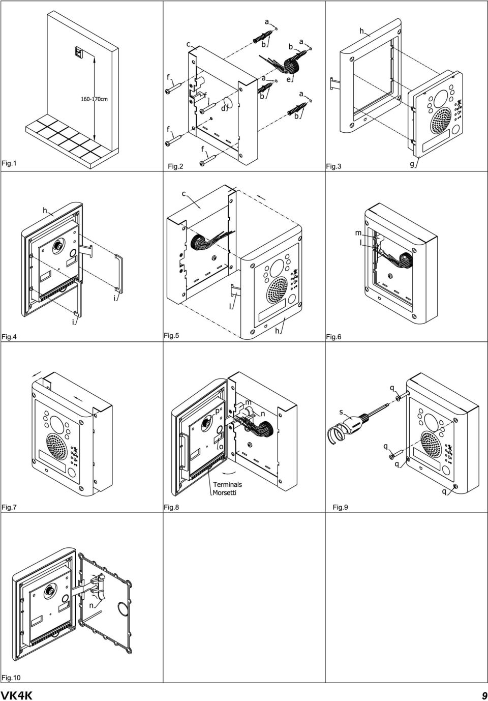
8 ollegamento alla Rete Elettrica, Installazione dell Alimentatore La realizzazione dell impianto deve essere eseguita nel rispetto delle vigenti normative nazionali, in particolare si raccomanda di: ollegare l impianto alla rete elettrica tramite un dispositivo di interruzione omnipolare che abbia una distanza di separazione del contatto di almeno mm per ciascun polo e che sia in grado di disconnettere tutti i poli simultaneamente; Il dispositivo di interruzione omnipolare deve essere posizionato in un luogo tale da consentirne un facile accesso in caso di necessità INSTALLAZIE DELL ALIMENTATORE Rimuovere i coperchi coprimorsetti svitando le relative viti e tirandoli verso l alto; Fissare l alimentatore su barra DIN o direttamente a parete utilizzando le viti ed i relativi tasselli ad espansione forniti a corredo; Togliere la tensione di rete tramite il dispositivo sopra indicato ed eseguire le connessioni come previsto dagli schemi proposti (la connessione verso la rete va effettuata in base alla tensione disponibile o 0Vac) Verificare che non vi siano errori di connessione e che i fili siano ben serrati nei morsetti; Inserire a scatto i coperchi coprimorsetti e fissarli tramite le relative viti; Eseguiti tutti i collegamenti, dare tensione all impianto onnection to Mains, Power Supply Mounting Instructions The system must be installed according to national rules in force, in particular we recommend to: onnect the system to the mains through an allpole circuit breaker which shall have contact separation of at least mm in each pole and shall disconnect all poles simultaneously; The allpole circuit breaker shall be placed for easy access and the switch shall remain readily operable POWER SUPPLY INSTALLATI Remove the terminal side covers by unscrewing the retaining screws; Fix the power supply to a DIN bar or directly to the wall using two expansion type screws; Switch off the mains using the circuit breaker mentioned above and then make the connections as shown on the installation diagrams; heck the connections and secure the wires into the terminals; Replace the terminal covers and fix them using the relevant screws; When all connections are made, restore the mains Installazione Posto Esterno Door Station Mounting POSTO ESTER DA SUPERFIIE Appoggiare la scatola da superficie alla parete lasciando circa 0cm tra la parte alta della scatola ed il terreno come mostrato in figura quindi prendere i riferimenti per i fori di fissaggio tenendo presente che il gruppo di fili e (fig) deve passare attraverso l apertura d presente sulla scatola da superficie Se non indicato, il verso di montaggio della scatola deve essere tale da far rimanere la cerniera sulla sinistra; ome mostrato in figura, realizzare i fori di fissaggio a, inserire al loro interno i tasselli ad espansione b e, facendo passare i fili di collegamento e attraverso l apertura d, fissare la scatola da superficie c alla parete utilizzando le viti f; Inserire il modulo g nel supporto h come mostrato in figura ; Prima di agganciare alla scatola da superficie il supporto completo di modulo, inserire i fermi antieffrazione i come mostrato in figura ; Muovendo il supporto h come mostrato dalle frecce di figura, procedere all aggancio dello stesso alla scatola da superficie c Il perno l deve inserirsi nel relativo alloggiamento m come mostrato in figura ; ome mostrato in figura, tirare il supporto moduli h indietro compiendo contemporaneamente un leggero movimento a sinistra come suggerito dalle frecce; ome mostrato in figura, ruotare il supporto moduli h nella direzione consigliata dalla freccia e provvedere ad agganciare il fermo n all alloggiamento m del perno Assicurato il supporto alla scatola da superficie, svolgere le seguenti operazioni: eseguire le opportune configurazioni dell unità tramite i jumper ed il dipswitch a vie accessibili dall apertura o effettuare i necessari collegamenti con l ausilio del giravite (lato piatto della lama) fornito a corredo; regolare l angolo di ripresa della telecamera agendo sulla vite p; Ad impianto testato e funzionante, procedendo a ritroso delicatamente, chiudere e fissare il supporto moduli alla scatola da superficie utilizzando il giravite s (lato torx della lama) e le viti q come mostrato in figura Nota bene: non serrare le viti più del necessario POSTO ESTER DA IASSO Se il posto esterno è da incasso occorre procedere come di seguito indicato: Dopo aver opportunamente protetto i fori di fissaggio per il supporto moduli, murare la scatola da incasso ad una altezza tale da avere circa 0cm tra la parte alta della scatola e il terreno avendo cura di far passare il gruppo di fili e (fig) attraverso uno dei fori precedentemente aperti sul fondo della scatola Se non indicato sul fondo della scatola, il verso di muratura deve essere tale da lasciare la cerniera sulla sinistra Fare attenzione affinché la scatola sia murata a filo muro finito; Proseguire dal passo della installazione da superficie tenendo presente che al punto il fermo n va agganciato come mostrato in figura 0 Note La lama del giravite fornito a corredo ha due punte, una piatta ed una torx Sfilare la punta e reinserirla nel manico scegliendo il lato desiderato SURFAE DOOR STATI Place the surface box against the wall (0cm between the top of the box and the floor lever as show in figure ) and mark the fixing holes for the wall plugs and hole for the cables e (fig) Observe the orientation of the box with the hinge on the left; As shown on figure, drill the fixing holes a, insert the wall plugs b and feed the cables e through the surface box opening d, fix surface box c to the wall using the screws f; Hook the module g in the support frame h as shown in figure ; Before the installation of the module support frame, fit the two antitampering locks provided as shown in figure ; As shown in figure, hook the module support frame h (complete with modules) to surface box c moving the frame as suggested from pointers Ensure that the pivot l (fig) goes inside the relevant housing m as shown in figure As shown in figure, pull back the module support frame h while moving it slightly to the left as suggested by the pointers; As shown in figure, open the module support frame h as suggested by the pointer, hook the hinge lock n to the hinge m When the support frame is hooked to the surface box, do the following operations: make the required settings operating the two jumpers and the way dipswitch accessible from the opening o (fig) make the required connections using the screwdriver provided (blade flat side); adjust the camera viewing angle by operating the screw p (fig); When the system has been tested and is working correctly, move back the module support frame carefully, fix it to the surface box using the provided screwdriver s (blade torx side) and the pin machine torx screws q as shown in figure Note: do not over tighten the screws more than is necessary FLUSH DOOR STATI If the door station is a flush, carry out the following: Protect the module support frame fixing holes from dust then embed the back box into the wall (0cm between the top of the box and the floor level as shown on the figure ) feeding the cables e (fig) through a previous opened hole in the box Observe the direction of the box ensuring the hinge is on the left and take care that the box profile is in line with the finished wall profile; ontinue from step of surface mounting, but at step hook the hinge lock n as shown on figure 0 Notes The screwdriver s blade has two sides, one flat and one torx, to select one of them unplug the blade from the screwdriver body and plug it into the required side VKK

9 VKK
10 Istruzioni di Montaggio del Videocitofono Art, e Videophone Mounting Instructions Art, and PIASTRA DI FISSAGGIO E SHEDA DI NESSIE Appoggiare al muro la piastra di fissaggio A come indicato in fig (cm da terra); prendere i riferimenti dei quattro fori per l inserimento dei tasselli ad espansione B (fig) e, nel caso si impieghi, prendere il riferimento per la scatola da incasso (fig), che dovrà essere murata in posizione centrale rispetto all apertura D al fine di agevolare il passaggio dei fili come mostrato in fig Murare (se impiegata) la scatola da incasso (), eseguire i fori ed inserire i tasselli ad espansione B Passare i cavi nell apertura D e fissare la piastra A con le viti E (fig) utilizzando un giravite a croce Appoggiare la scheda di connessione F sulla piastra A come mostrato in fig; inserire () i fili (che devono essere più corti possibile) nelle morsettiere G ed H e serrare con un giravite a taglio Fissati i fili, sfilare la scheda di connessione F (fig), ruotarla di 0º in senso antiorario ed infilarla nella propria sede come mostrato in fig APPLIAZIE DEL VIDEOITOFO ALLA PIASTRA Avvicinare, come da fig, il videocitofono L alla piastra A per agevolare la connessione del flat I ome mostrato in fig inserire il connettore del flat I, che fuoriesce dalla parte posteriore del videocitofono, nel connettore M della scheda di connessione F Facendo corrispondere le fessure presenti sulla base del videocitofono L con i incastri N della piastra A, appoggiare il video sulla piastra e spingerlo verso il basso fino allo scatto, compiendo un movimento come mostrato dalle frecce in fig Per rimuovere il videocitofono, spingere con un giravite a taglio il dente O verso il muro e, contemporaneamente, tirare il videocitofono verso l alto TE () Si consiglia di utilizzare una scatola da incasso (non in dotazione) al fine di contenere l eventuale lunghezza eccedente dei fili () I collegamenti alla morsettiera devono essere eseguiti rispettando gli schemi forniti a corredo del videocitofono, per applicazioni differenti da quelle degli schemi standard, rivolgersi al proprio rivenditore MOUNTING PLATE & PB NETIS Place the mounting plate A against the wall as shown in fig (cm from floor level); and mark the fixing holes for the four wall plugs B (fig) and for the back box if used (fig) which must be flushed into the wall in line with the opening D as shown in fig Once the back box () is flushed into the wall (if used), drill the four fixing holes and insert the wall plugs B Thread the cables through the opening D and fix the mounting plate A to the wall with the screws E (fig), using a Philips screwdriver Fit the PB F against the mounting plate A as shown in fig; insert the wires () (As short as possible) into terminals GH Secure them using a terminal screwdriver Unclip the PB F (fig), rotate it 0º anticlockwise and fit it into its housing as shown in fig INSTALLING THE VIDEOPHE TO THE MOUNTING PLATE As shown in fig, move the videophone L close to the mounting plate A so that the ribbon cable will reach the connector I As shown in fig, connect the female plug on the ribbon cable I coming from the videophone to the male plug connector M on the PB F Place the videophone L against the hooks N on the mounting plate A and push down: the videophone will automatically lock into place using clasp O as shown in fig To remove the videophone from the wall, push the clasp O in the direction of the wall with a screwdriver and at the same time push the videophone upwards TES () We recommend using a back box in order to contain excess wire behind the back plate () The wires must be connected to the terminals as shown on the relevant wiring diagrams 0 VKK
 utilizzando un giravite a croce Appoggiare la scheda di connessione F sulla piastra A come")
11 Sezione Fili e Ricerca Guasti Section of Wires & Troubleshooting Guide ZIE FILI Per le connessioni Video e quelle audio suggeriamo di utilizzare delle coppie di fili intrecciati: una coppia per la linea video (morsetti e, segnali V e V ) ed una coppia per quella audio (morsetti e, segnali e ) TI OF WIRES Video connections and Audio connections must be wired in twisted pair : pair the video lines (terminals and signals V and V ), pair the audio lines (terminals and signals and ) Dal trasformatore al videocitofono max 0 mt: fili da mm Dal videocitofono al posto esterno: per VKK, VKK fino a 0m : tutti i fili da 0 mm da 0 a 00m : fili + e da 0 mm; tutti gli altri da 0 mm da 00 a 00m : fili + e da mm; tutti gli altri da 0 mm Between transformer and videophone 0 mt max: wires mm Between videophone and outdoor station: For VKK, VKK up to 0 mt : all wires 0 mm from 0 to 00 mt : wires + and 0 mm; other wires 0 mm from 00 to 00 mt : wires + and mm; other wires 0 mm per il VKK fino a 0m : fili + e da 0 mm; tutti gli altri 0 mm da 0 a 00m : fili + e da mm; tutti gli altri 0 mm da 00 a 00m : fili + e da mm; tutti gli altri 0 mm For VKK up to 0 mt from 0 to 00 mt from 00to 00 mt : wires + and 0 mm; other cables 0 mm : wires + and mm; other cables 0 mm : wires + and mm; other cables 0 mm RIERA GUASTI In caso di malfunzionamenti effettuare i seguenti controlli preliminari: Verificare che i conduttori siano collegati in accordo a quanto indicato nello schema d istallazione e che questi siano saldamente serrati nei morsetti (videocitofono, portiere elettrico o alimentatore); Verificare che sia presente la tensione di rete tra i morsetti 0Vac (o Vac) e 0 del trasformatore di alimentazione Art0K; Verificare la presenza della tensione Vac in uscita dal trasformatore Art0K L eventuale assenza di tensione può essere causata dall interruzione del fusibile da,a, in tal caso togliere la tensione di rete, accertarsi che non vi siano sovraccarichi o cortocircuiti e sostituire il fusibile con uno uguale o equivalente; Verificare che la tensione fra i morsetti + e del portiere elettrico sia compresa tra e 0Vdc; Se il problema non è tra quelli sopra indicati, consultare la seguente tabella Sintomo ausa Soluzione L Art (posto esterno) non riesce a far squillare l interno (il LED campana si accende per circa secondi): Errato collegamento dei fili tra l Art e l Art, verificare in particolare il filo audio/ dati Sezione dei fili inadeguata L indirizzo programmato sul dipswitch dell Art non è corretto La chiamata dal posto esterno Sezione dei fili inadeguata funziona correttamente, ma alla risposta cade la comunicazione: Durante la conversazione non è Sezione dei fili inadeguata possibile aprire la porta: Durante la conversazione non si riesce ad aprire la porta, ma il LED chiave dell Art si accende: La fonia va dal posto esterno verso l interno ma non viceversa: Volume audio di conversazione non adeguato: Rumore di fondo durante la conversazione: Non funziona il servizio di autoaccensione : Non funziona la chiamata intercomunicante: Ponticello mobile J in posizione errata Fili della serratura collegati in maniera errata Tipologia della serratura non adatta Filo interrotto o in corto circuito Trimmer di regolazione volume dell Art impostati in modo non appropriato I fili comuni sono stati canalizzati insieme a cavi di rete a 0 o 0Vac I fili di alimentazione Vac del videocitofono Art sono stati canalizzati insieme ai fili comuni per un tratto troppo lungo Premuto il tasto autoaccensione per un numero di volte diverso dall ID del posto esterno da accendere Premuto il tasto chiave per un numero di volte diverso dall indirizzo del videocitofono da chiamare L immagine mostrata dal monitor del videocitofono è distorta o riflessa: Segnali V e V non connessi, scambiati o in corto circuito Gli switch del dipswitch a vie del ultimo videocitofono non sono entrambi ad Se presente l Art, linee passanti V e V non chiuse Non funziona la chiamata di piano: onnessione errata o pulsante difettoso Verificare la connessione dei fili comuni e rimuovere eventuali cortocircuiti Aumentare la sezione dei fili o raddoppiarla utilizzandone altri disponibili Verificare l indirizzo del videocitofono Aumentare la sezione dei fili o raddoppiarla utilizzandone altri disponibili Aumentare la sezione dei fili o raddoppiarla utilizzandone altri disponibili Verificare sull Art la posizione del ponticello J Verificare il collegamento dei fili Verificare che la tipologia di alimentazione della serratura (ac o dc) corrisponda all impostazione di J ontrollare il collegamento del filo Regolare opportunamente i trimmer fino a raggiungere il livello di volume desiderato Isolare i fili comuni da cavi di rete o altri cavi ad alta tensione analizzare i fili d alimentazione del videocitofono separatamente dai fili comuni o insieme per un tratto più breve Verificare il valore dell ID del posto esterno () e premere il pulsante di autoaccensione tante volte quant è il valore dell ID Verificare la corretta impostazione degli indirizzi dei videocitofoni Verificare continuità ed isolamento dei fili V,V Mettere ad on entrambi gli switch hiudere le linee passanti V,V verso massa con le resistenze fornite a corredo ontrollare la connessione o sostituire il pulsante TROUBLESHOOTING GUIDE In case of system failure, try the following as preliminary checks: heck that the cables are connected as shown in the installation diagram and that the cables are firmly fixed into the relevant terminals; heck that the mains voltage is available on terminals 0Vac (or Vac) and 0 of the power transformer Art0K; heck the Vac voltage output of the power transformer Art0K If this voltage is not available it could be the,a fuse, in this case remove the mains voltage, remove possible shortcircuits or overload sources then replace the fuse with an equal or equivalent one heck that the voltage between the terminals + and of the speaker unit is between and 0Vdc If the problem is not listed above, try the tests the following table Symptom ause Solution The Art (door station) is not able to call the extension (the bell LED is switched on for seconds): External call works but when answered the communication fails: During the conversation it is not possible to open the door: During the conversation it is not possible to open the door but the key LED (Art) switches on for the programmed time: Speech only from outside to inside: Low volume of speech: Noise over the speech line during the conversation: amera recall service does not work: Intercommunicating call does not work: Wrong connection between Art and able size too small Programmed videophone address incorrect able size too small able size too small Incorrect position of J jumper Electric lock wires unconnected or in short Wrong electric lock type heck the common wire connections especially wire (speech line/data) Increase cable size or double up using two wires for each signal heck videophone address on dipswitches Increase cable size or double section using two wires for each signal Increase cable size or double section using two wires for each signal heck J position on the Art heck wires connection heck that the electric lock type (ac or dc) is suitable for the J position chosen Wire broken or in short heck connection of wire Volume trimmers of Art require adjustment The common wires cabled together with 0 or 0Vac power lines The common wires cabled together with Vac videophone power supply wires amera recall button pressed for a number of times different from the ID of the door station to be switched on Key button pressed for a number of times different from the videophone address value The video shown on the monitor V,V signals unconnected, is of a bad quality and the image is distorted or double exchanged or put in short The switches of the two way dipswitch are not both in position V,V of the last Art (if present) not closed with Ohm resistor call does not work: Wrong connection or call button broken Adjust the trimmers until the required volume is reached Separate the common wires from the high voltages cables Separate the common wires from the two Vac wires or cable them together only for a short distance heck the ID () of the door station to be recalled and press the camera recall button as many time as the ID value heck the address of the videophone you are calling and try again heck that the wires are not broken and isolated Set both switches in position lose through V,V of the Art toward the ground with provided resistors heck connection or replace the button VKK

12 Schemi d Installazione Note e Suggerimenti Tutti gli schemi, anche se non espressamente indicato, si riferiscono alle versioni da incasso o superficie, bianco e nero o colori dei relativi kit Le connessioni tratteggiate si riferiscono a collegamenti facoltativi ( bell, Push to exit e Door monitor ) Alcuni schemi mostrano indicazioni per il collegamento di serrature Vdc: tali indicazioni sono da ritenersi valide per ogni schema del presente manuale Installation Diagrams Notes & Suggestions All diagrams refer to all kits versions: flush or surface, color or black & white Dashed connections refer to optional connections ( bell, Push to exit & Door monitor ) Some diagrams show how to connect a Vdc electric lock: these directions are suitable for all diagrams in this manual Descrizione Schema Nr Pag PagNo Diagram Description Lo schema mostra l installazione di un videokit standard monofamiliare Tutti gli schemi proposti sono da ritenersi validi per impianti bianco e nero o colori, da incasso o superficie The diagram shows the installation of a one way standard videokit All diagrams shown are valid for B&W or olor systems with surface or flush mount door station Lo schema mostra l installazione di un videokit monofamiliare ed il collegamento di un citofono ed una suoneria addizionali Le connessioni mostrate per il citofono e la suoneria addizionali sono valide per tutti gli altri schemi del manuale The diagram shows the installation of one way videokit with additional intercom and extension sounder onnections shown for the intercom and the sounder are suitable for all diagrams in this manual Lo schema mostra l installazione di un videokit monofamiliare con l aggiunta di un secondo posto esterno per la realizzazione di un sistema a ingressi Da notare l utilizzo del relè Art0N per commutare il segnale video tra i ingressi e l impostazione di un diverso indirizzo per ciascuno dei posti esterni Lo schema mostra l installazione di un videokit monofamiliare con l aggiunta di videocitofoni per la realizzazione di un sistema intercomunicante Da notare l utilizzo dell Art per la distribuzione del segnale video e l impostazione del dipswitch ad video di ciascun videocitofono: switch ad OFF e switch ad ad indicare l appartamento e l intercomunicazione tra videocitofoni dello stesso appartamento mentre gli switch e indicano il numero () di interno Lo schema mostra l installazione un videokit monofamiliare con esempi di applicazioni dei pulsanti di servizio e il collegamento di un videocifono addizionale senza l utilizzo del distributore video Art Da notare la configurazione del dipswitch a vie di ciascun videocitofono: per il primo (in ordine di collegamento) entrambi gli switch sono ad OFF, mentre nel secondo sono entrambi ad Lo schema mostra l installazione di un videokit bifamiliare Da notare l utilizzo del distributore video Art e la configurazione del dipswitch ad vie dei due videocitofoni: switch ad OFF per il videocitofono nell appartamento, ad per il videocitofono nell appartamento e switch ad OFF per entrambi ad indicare intercomunicazione tra appartamenti Lo schema mostra l installazione di un videokit bifamiliare con l aggiunta di un secondo posto esterno per la realizzazione di un sistema a ingressi Da notare l utilizzo del relè Art0N per commutare il segnale video tra i ingressi e l impostazione di un diverso indirizzo per ciascuno dei posti esterni Lo schema mostra l installazione di un videokit bifamiliare con l aggiunta di posti esterni per la realizzazione di un sistema a ingressi Da notare la configurazione degli indirizzi dei posti esterni (dipswitch a vie switch e ) e l utilizzo degli Art0N per la commutazione del segnale video tra i ingressi Lo schema mostra l installazione di un videocode kit monofamiliare Questo tipo di kit abbina le prestazioni di un videokit alle funzioni offerte dalle tastiere digitali VIDEX: l utente, digitando il proprio codice d accesso, può aprire la porta d ingresso dall esterno 0 The diagram shows the installation of one way videokit with the addition of a second door station to make a entrance system Note the use of the relay Art0N to switch the video signal between the two door stations and the different address set for each door station The diagram shows the installation of one way videokit with additional videophones to make an intercommunicating system Note the use of the Art to distribute the video signal and the setup of the way dipswitch of each videophone: switch OFF and switch to point out flat and intercommunication within the same flat while switches and set the extension address () The diagrams shows the installation of one way videokit with example of how to use the service push button and how to connect an additional videophone without using the video distributor Art Note the setup of the way dipswitch of each videophone: both switches OFF for the first videophone following the connection order, both switches for the second videophone (the last) The diagram shows the installation of a two way videokit Note the use of video distributor Art and the setup of the way dipswitch of each videophone: switch OFF for the videophone in flat, switch for the videophone in the flat, switch OFF for both videophones to set intercommunication between two flats The diagram shows the installation of a two way videokit with the addition of a second door station to make a two entrance system Note the use of the relay Art0N to switch the video signal between the two door stations and the different address set for each door station The diagram shows the installation of a two way videokit with additional door stations to make a entrance system Note the different address set for each door station () and the use of the Art0N to switch the video signal between the door stations The diagram shows the installation of one way videocode kit This videocode kit adds the features offered by a VIDEX digital codelock: the user can open the door from outside by entering the relevant access code on the keypad Lo schema mostra l installazione di un videprox kit monofamiliare Questo tipo di kit abbina le prestazioni di un videokit alle funzioni offerte dal lettore chiavi di prossimità standalone VIDEX: l utente può aprire la porta d ingresso avvicinando la propria chiave al lettore The diagram shows the installation of one way videprox kit This videprox kit adds the features offered by a VIDEX standalone proximity key reader: the user can open the door from outside by simply presenting a card/fob to the external reader Lo schema mostra l installazione di un videfinger kit monofamiliare Questo tipo di kit abbina le prestazioni di un videokit alle funzioni offerte dal lettore d impronte standalone VIDEX: l utente può aprire la porta d ingresso utilizzando le proprie dita The diagram shows the installation of one way videfinger kit This videfinger kit adds the features offered by a VIDEX standalone fingerprint reader: the user can open the door from outside simply swiping their finger on the reader Lo schema mostra l installazione del VKK con memoria video Viene utilizzato un videocitofono speciale con memoria video Art ed un alimentatore speciale Art0K/MV The diagram shows the VKK version with memory board It is used a special videophone with memory board Art and a special power supply Art0K/MV VKK
 Some diagrams show how to connect a Vdc electric lock: these directions are suitable for all diagrams in this manual Descrizione")
13 Videokit VKK, VKK, VKKS, VKKS Videokit VKK, VKK, VKKS, VKKS VIDEOITOFO / VIDEOPHE Art Art0 R 0 V Art0K 0Vac 0 Vac TRASFORMATORE / TRANSFORMER ART0K Using Electric Lock Vdc 0A Max on serratura elettrica Vdc 0A Max Push to Exit Art Vdc Art Vout V V Vout V V V A Door Monitor Title: Data creazione: Foglio VKK, VKKS, VKK, VKKS 0/0/00 Titolo: Data modifica: VKK, VKKS, VKK, VKKS Videx Electronics SpA Via del Lavoro, 00 Monte Giberto (AP) Phone: + 0 Fax + 0 wwwvidexit info@videxit Notes: Autore: Marco Rongoni Note: odfile: 0/0/00 vkk0dwg VKK /
 Phone: + 0 Fax + 0 wwwvidexit info@videxit Notes: Autore: Marco Rongoni Note: odfile: 0/0/00 vkk0dwg")
14 Videokit VKK, VKK, VKKS, VKKS con accessori addizionali Videokit VKK, VKK, VKKS, VKKS with additional accessories VIDEOITOFO / VIDEOPHE Art Art0 R 0 V Art0K 0Vac 0 Vac TRASFORMATORE / TRANSFORMER ART0K ITOFO Addizionale / Additional INTEROM Art RED YELLOW SUERIA AGGIUNTIVA / ADDITIAL SPEAKER ARTA VOLREG BLAK GREEN Using Electric Lock Vdc 0A Max on serratura elettrica Vdc 0A Max Push to Exit Art Vdc Art Vout V V Vout V V V A Door Monitor Title: VKK, VKKS, VKK, VKKS Plus additional accessories Titolo: VKK, VKKS, VKK, VKKS più accessori addizionali Videx Electronics SpA Via del Lavoro, 00 Monte Giberto (AP) Phone: + 0 Fax + 0 wwwvidexit info@videxit Notes: Note: Data creazione: Foglio 0/0/00 Data modifica: 0/0/00 Autore: Marco Rongoni odfile: vkk00dwg / VKK
 Phone: + 0 Fax + 0 wwwvidexit info@videxit Notes: Note: Data creazione: Foglio 0/0/00 Data modifica: 0/0/00 Autore: Marco Rongoni")
15 Videokit VKK, VKK, VKKS, VKKS con posto esterno addizionale sistema a ingressi Videokit VKK, VKK, VKKS, VKKS with additional door station two entrances system VIDEOITOFO / VIDEOPHE Art Art0 R 0 V Art0K 0Vac 0 Vac TRASFORMATORE / TRANSFORMER ART0K Door Monitor Door Monitor V A V A Art Art0N O 0 Vout V V V V Vdc Vout V V Using Electric Lock Vdc 0A Max on serratura elettrica Vdc 0A Max Art Vout Art Push to Exit Push to Exit Title: Data creazione: Foglio VKK, VKKS Plus additional door station (two entrances system) 0/0/00 Titolo: Data modifica: VKK, VKKS con posto esterno addizionale (sistema a due ingressi) Notes: Videx Electronics SpA Via del Lavoro, 00 Monte Giberto (AP) The two door stations are set with different ID Phone: + 0 Fax + 0 wwwvidexit info@videxit Note: odfile: I due posti esterni sono impostati con indirizzi differenti /0/00 VKK Autore: Marco Rongoni vkk00dwg /
 Notes: Videx Electronics SpA Via del Lavoro, 00 Monte Giberto (AP) The two door stations are set with different ID Phone: + 0 Fax + 0 wwwvidexit info@videxit Note: odfile: I")
16 Videokit VKK, VKK, VKKS, VKKS con videocitofoni addizionali sistema intercomunicante Videokit VKK, VKK, VKKS, VKKS with additional videophones intercommunicating system V A 0 Art0 0 Art0 0 VIDEOITOFO / VIDEOPHE VIDEOITOFO / VIDEOPHE VIDEOITOFO / VIDEOPHE Art0 R R R V V V Art0K 0Vac 0 Vac Art0K 0Vac 0 Vac Art0K 0Vac 0 Vac x V Vd + Vc Vd + V + Vc Art Vb Va + Vb Va + V V + Door Monitor Art Vout V V V Vdc 0 Art0K 0Vac 0 Vac VIDEOITOFO / VIDEOPHE Art0 Art R Using Electric Lock Vdc 0A Max on serratura elettrica Vdc 0A Max ArtD Vout V V Title: VKK, VKK, VKKS, VKKS plus additional videophones Titolo: VKK, VKK, VKKS, VKKS con videocitofoni addizionali Notes: Videx Electronics SpA Via del Lavoro, 00 Monte Giberto (AP) Flat address of all videophones is the same while videophone address is different for each videophone Phone: + 0 Fax + 0 wwwvidexit info@videxit Note: L'indirizzo d'appartamento di tutti i videocitofoni è lo stesso mentre l'indirizzo di ciascun videocitofono è differente Data creazione: Foglio 0/0/00 Data modifica: 0/0/00 Autore: Marco Rongoni odfile: vkk00dwg / VKK
 Flat address of all videophones is the same while videophone address is")
17 Videokit VKK, VKK, VKKS, VKKS Esempi: collegamento videocitofono addizionale ed utilizzo pulsanti di servizio Videokit VKK, VKK, VKKS, VKKS Examples: additional videophone connection and service push buttons use Art Art0 R 0Vac 0 Vac Art0K 0 V V 0 Art0K Art0 R Vac 0 0Vac Art V A Vout V V VIDEOITOFO / VIDEOPHE VIDEOITOFO / VIDEOPHE Service push button Art "S" Service push button Art0N ARTN 0V D O 0V Peripheral V V + 0 Art0N 0 0/0 Hz O 0 Art Title: Data creazione: Foglio VKK, VKKS with additional videophone without video distributor Art 0/0/00 Titolo: Data modifica: VKK, VKKS con videocitofono addizionale ma senza distributore video Art Notes: Videx Electronics SpA Via del Lavoro, 00 Monte Giberto (AP) Phone: + 0 Fax + 0 wwwvidexit info@videxit Note: odfile: //00 VKK Autore: Marco Rongoni vkk00dwg /
 Phone: + 0 Fax + 0 wwwvidexit info@videxit Note: odfile: //00 VKK Autore:")
18 Videokit VKK, VKK, VKKS, VKKS Videokit VKK, VKK, VKKS, VKKS Art Art0 R 0Vac 0 Vac Art0K 0 V V 0 Art0K Art0 R Vac 0 0Vac Art x V Vd + Vd Vc + V + Vc Art + V V + Va Va + Vb Vb Using Electric Lock Vdc 0A Max on serratura elettrica Vdc 0A Max Vdc Push to Exit ArtD Vout V V V V APPARTAMENTO / FLAT APPARTAMENTO / FLAT ArtD Vout V A Door Monitor Title: VKK, VKKS Titolo: VKK, VKKS Videx Electronics SpA Via del Lavoro, 00 Monte Giberto (AP) Phone: + 0 Fax + 0 wwwvidexit info@videxit Notes: Note: Data creazione: Foglio 0/0/00 Data modifica: 0/0/00 Autore: Marco Rongoni odfile: vkk00dwg / VKK

19 Videokit VKK, VKK, VKKS, VKKS con posto esterno addizionale: sistema a ingressi APPARTAMENTO / FLAT Videokit VKK, VKK, VKKS, VKKS with additional door station: two entrances system APPARTAMENTO / FLAT VIDEX VIDEX PRIVAY DOOR OPEN S Art Art0 R 0 0 Art0 R PRIVAY DOOR OPEN S Art 0Vac 0 Vac Art0K V V Art0K Vac 0 0Vac x V Vd + Vd Vc + V + Vc Art + V V + Va Va + Vb Vb V A Vout V V V V Art0N O 0 ArtD ArtD Vout Title: VKK, VKKS with one additional door station Titolo: Push to Exit VKK, VKKS con un posto esterno addizionale Videx Electronics SpA Via del Lavoro, 00 Monte Giberto (AP) Phone: + 0 Fax + 0 wwwvidexit info@videxit Notes: Art0N is required to exchange video signal Note: Art0N è richiesto per lo scambio del segnale video proveniente dai posti esterni VKK Push to Exit Data creazione: 0/0/00 Data modifica: /0/00 Autore: Foglio / Marco Rongoni odfile: vkk00dwg

20 Videokit VKK, VKK, VKKS, VKKS con posti esterni addizionali: entrances system Videokit VKK, VKK, VKKS, VKKS with additional door stations: entrances system FLAT / APPARTAMENTO VIDEX x V Vd + Vc Vd + V + Vc Art Vb Art V A S V Va + Vb Va + V V + 0 Art0K 0Vac 0 Vac Art0 R 0 Art0 PRIVAY DOOR OPEN FLAT / APPARTAMENTO VIDEX PRIVAY DOOR OPEN Art S V Art0K 0Vac 0 Vac R V V Vout ArtD O V A 0 O V A 0 O V A V V Art0N Vout V V ArtD Art0N Vout V V ArtD Art0N 0 Vout ArtD Title: VKK, VKK, VKKS, VKKS with additional door stations Titolo: VKK, VKK, VKKS, VKKS con posti esterni addizionali Notes: Videx Electronics SpA Via del Lavoro, 00 Monte Giberto (AP) Each door station must be set with a different address () 0 Phone: + 0 Fax + 0 wwwvidexit info@videxit Note: iascun posto esterno deve essere configurato con un indirizzo differente () Data creazione: Foglio 0/0/00 Data modifica: 0/0/00 Autore: Marco Rongoni odfile: vkk00dwg / VKK
 Each door station must be set with a different address () 0 Phone: + 0 Fax + 0 wwwvidexit info@videxit Note: iascun posto esterno deve essere")
Art.33,34,3512 Videocitofono coax / no coax
 Coax / non-coax videophone Art.33,34,3512 Videocitofono coax / no coax INSTALLATION INSTRUCTION ISTRUZIONI D INSTALLAZIONE INSTALLING THE VIDEOPHONE ONTO THE MOUNTING PLATE As shown in fig.1, move the
3600 SERIES VIDEOPHONES VIDEOCITOFONI SERIE 3600 161
 3600 SERIES VIDEOPHES VIDEOCITOFI SERIE 3600 161 161 62 46 218 178 218 178 Art.3618 Art.3612 FOR TRADITIAL VIDEO SYSTEMS USING COAX VIDEO SIGNAL OR BALANCED VIDEO SIGNAL ART.3612 Videophone using 3.5 full
Norme Tecniche Owner s Manual. VIDEOKIT Serie
 VIDEOKIT Serie VRKV Series VIDEOKIT Videokit antivandalo Monofamiliari e Bifamiliari One Way, Two Way Vandal Resistant Videokit Norme Tecniche Owner s Manual Videx Electronics SpA Via del Lavoro, 30 Monte
Intercoms & videointercoms Citofoni e Videocitofoni series Serie 3000
 Intercoms & videointercoms Citofoni e Videocitofoni 3000 series The 3000 series intercoms and video intercoms are the result of specific research and development into new designs and materials. One of
PCB conn. Art.3980 Signal. Names
 Remove R1 resistor Rimuovere la resistenza R1 SEGNALI SIGNALS La Tabella 1 indica i segnali (e le relative denominazioni) presenti sulla Table 1 shows the videophones Art.3351,3451,3551 connections (and
VK4K, VK4K-S Videokit Monofamiliare con videocitofono e telecamera bianco e nero. VK4K, VK4K-S One way videokit with B&W camera and videophone
 VK4K, VK4K-S Videokit Monofamiliare con videocitofono e telecamera bianco e nero VK4K, VK4K-S One way videokit with B&W camera and videophone I videokit della serie VK4K fanno parte di una nuova linea
Art.SL5456 VK4K. VIDEOPHONE 5000 SERIES SLIM Push Buttons, LEDs, Controls, Settings & Signals
 1 2 3 4 5 678 1 2 VIDEOCITOFO SERIE 5000 SLIM Pulsanti, LED, Controlli, Impostazioni e Segnali VIDEOPHE 5000 SERIES SLIM Push Buttons, LEDs, Controls, Settings & Signals 1 2 3 4 5 6 7 8 9 10 11 12 13 14
Outdoor wireless wall switch
 www.trust.com SECURITY PLUS-LINE AGST-8800 USER MANUAL MULTI LANGUAGE Item 71151 Version 1.0 Visit www.trust.com for the latest instructions Outdoor wireless wall switch 1 2 3 OFF OFF OFF OFF ON + ON ON
SISTEMA DI ILLUMINAZIONE PER VERRICELLI WINDLASS LIGHTING SYSTEM
 Istruzioni per l uso Instructions for use SISTEMA DI ILLUMINAZIONE PER VERRICELLI WINDLASS LIGHTING SYSTEM WLS WINDLASS LIGHTING SYSTEM - 1 - Rev.01-2013 Italiano SISTEMA DI ILLUMINAZIONE PER VERRICELLI
RETROFIT KIT KONE - KRM - KCEAPM - KONEXION
 RETROFIT KIT KONE - KRM - KCEAPM - KONEXION 7IS-80416 30/01/2019 COMPONENTI / COMPONENTS Helpy 2W-V 12V MK (5HL-006) Cavo per kit retrofit Kone / Cable retrofit kit Kone (5KT-120) INSTALLAZIONE KRM / KRM
Norme Tecniche Owner s Manual. VIDEOKIT Serie. Series VIDEOKIT Mono-familiari e Bi-familiari One Way, Two Way
 VIDEOKIT Serie Series VIDEOKIT Monofamiliari e Bifamiliari One Way, Two Way Norme Tecniche Owner s Manual Videx Electronics S.p.A. Via del Lavoro, 60 Monte Giberto (AP) Italy Phone +9 07 6669 Fax +9 07
CVK8K. Norme Tecniche Owner s Manual. VIDEOKIT Serie. Series VIDEOKIT Mono-familiari e Bi-familiari One Way, Two Way.
 VIDEOKIT Serie CVK8K 6000 Series Range Series VIDEOKIT Mono-familiari e Bi-familiari One Way, Two Way Norme Tecniche Owner s Manual Videx Electronics S.p.A. Via del Lavoro, 63846 Monte Giberto (FM) - Italy
User Manual. Rev Date: 31/05/2018
 Size / Misure 8 50 500 60 150 POWER IN DMX IN DMX OUT 9 4. POWER+DMX out cable + M8 Female Connector 16,80 Connection kit included with the Startline cable / Kit di connessione compreso alla startline
CVK4K. Norme Tecniche Owner s Manual. VIDEOKIT Serie. Series VIDEOKIT Mono-familiari e Bi-familiari One Way, Two Way Series
 VIDEOKIT Serie CVK4K 3600 Series Series VIDEOKIT Mono-familiari e Bi-familiari One Way, Two Way Norme Tecniche Owner s Manual Videx Electronics S.p.A. Via del Lavoro, 1 63846 Monte Giberto (FM) - Italy
Norme Tecniche Owner s Manual. VIDEOKIT Serie
 VIDEOKIT Serie VR4KV Series VIDEOKIT Videokit antivandalo Monofamiliari e Bifamiliari One Way, Two Way Vandal Resistant Videokit Norme Tecniche Owner s Manual Videx Electronics SpA Via del Lavoro, 6304
5000 SERIES SLIM LINE VIDEO MONITORS VIDEOCITOFONI SERIE 5000 LINEA SLIM
 5000 SERIES SLIM LINE VIDEO MONITORS VIDEOCITOFONI SERIE 5000 LINEA SLIM 164 204 187 1 2 3 4 Art.SL5418 Art.SL5418+ Art.5981N 153 34 130 10 55 170 FOR TRADITIONAL VIDEO SYSTEMS USING COAX VIDEO SIGNAL
Expansion card. EXP-D8-120 I/O Interface Card 8 AC Opto-coupled Digital Inputs 8 DC Digital Outputs
 Expansion card EXP-D8-120 I/O Interface Card 8 AC Opto-coupled Inputs 8 DC Outputs Sommario / Contents Vi ringraziamo per avere scelto questo prodotto Gefran-Siei. Saremo lieti di ricevere all'indirizzo
VIDEOKIT SERIE VK4K VIDEOKIT BUS 6 FILI MONOFAMILIARI E BIFAMILIARI
 VIDEOKIT SERIE VK4K VIDEOKIT BUS FILI MONOFAMILIARI E BIFAMILIARI 4000 SERIES Videokit Serie VK4K Mono VK4K o bifamiliare WIRE BUS INTERCOMMUNICATING WIDE CAMERA OPT. WIDE FILI BUS Intercom. Opzione Wide
MD2208. Multi I/O Control Module D32305 Rev. B. Microdata Due Martec Group
 MD2208 Multi I/O Control Module D32305 Rev. B Descrizione Si tratta di unità, collegabili sul Loop dei sistemi di rilevamento incendio (FDS) della serie MD9800 o sul Branch dei sistemi della serie MD2010,
VIDEOCITOFONI VIDEOPHONES. Art.3511 Art.3531. Art.3311 Art.3411 Art.3331 Art.3431. Art.3980
 VIDEOPHONES VIDEOCITOFONI rt.3311 rt.3411 rt.3331 rt.3431 rt.3511 rt.3531 rt.3980 FOR COX VIDEO SYSTEMS RT.3311, 3411, 3511 Videophones with 4 flat screen monitor for coax video systems. re made from white
CVK4K. Norme Tecniche Owner s Manual. VIDEOKIT Serie. Series VIDEOKIT Mono-familiari e Bi-familiari One Way, Two Way. 6000 Series
 VIDEOKIT Serie VK4K 6000 Series Series VIDEOKIT Monofamiliari e Bifamiliari One Way, Two Way Norme Tecniche Owner s Manual Videx Electronics S.p.A. Via del Lavoro, 63846 Monte Giberto (FM) Italy Phone
CVR4KV. Norme Tecniche Owner s Manual. VIDEOKIT Serie
 VIDEOKIT Serie CVR4KV 6000 Series Series VIDEOKIT Videokit anti-vandalo Mono-familiari e Bi-familiari One Way, Two Way Vandal Resistant Videokit Norme Tecniche Owner s Manual Videx Electronics S.p.A. Via
TLR05S-350. Extender in corrente costante, 3 x 350mA per TLR04M_
 TLR05S-350 Extender in corrente costante, 3 x 350mA per TLR04M_350-500 IT DATI TECNICI Alimentazione Uscita Tipo di carico Sistema di collegamento master/slave/slave Distanza massima delle connessioni
RETROFIT KIT SCHINDLER
 RETROFIT KIT SCHINDLER - ETMA - TAM2 7IS-80428 13/03/2019 COMPONENTI / COMPONENTS Helpy 2W-V 12V MK (5HL-006) Cavo per kit retrofit Schindler / Cable retrofit kit Schindler (5KT-121) INSTALLAZIONE ETMA
TFT LCD -5 /COL Monitor a colori LCD TFT 5 senza fili 2.4 GHz 2.4 GHz Wireless CCD 5" TFT color LCD monitor
 I GB TFT LCD -5 /COL Monitor a colori LCD TFT 5 senza fili 2.4 GHz 2.4 GHz Wireless CCD 5" TFT color LCD monitor IS1168-AA Manuale di Installazione Installation manual 1/8 TFT LCD-5 /COL GUIDA DI INSTALLAZIONE
Pagina 2 di 9 A - OGGETTO A - OBJECT B - SCOPO B - SCOPE. Instruction Sheet Rev. A
 COMPARTMENT A - OBJECT Wired fuse and relay box for engine compartment (P/N 1745062). Base box supply with sealing and spacer rings assembled whereas cover is in kit into same packaging. Base box have
MODALITA DI IMPIEGO PD
 MODALITA DI IMPIEGO PD MISURA CONCORDANZA/ 1. Accendere il dispositivo tramite interruttore a slitta situato sul lato destro; 2. All atto dell accensione il dispositivo esegue un test di funzionamento
START-LINE AYCT-202 USER MANUAL MULTI LANGUAGE. Item Version 2.0 Visit for the latest instructions REMOTE CONTROL
 START-LINE AYCT-202 USER MANUAL MULTI LANGUAGE Item 71164 Version 2.0 Visit www.trust.com for the latest instructions REMOTE CONTROL AYCT-202 REMOTE CONTROL 1 Arm Turn bulb ON 2 Channel selection Dim up
USER MANUAL MANUALE D USO BE Additional 12-zone. keyboard for BM 2006 paging microphone. - - Tastiera addizionale per base microfonica BM 2006
 USER MANUAL MANUALE D USO -- Additional 12-zone BE 2012 keyboard for BM 2006 paging microphone - - Tastiera addizionale per base microfonica BM 2006 INDEX INDICE ENGLISH SAFETY PRECAUTIONS DESCRIPTION
RELAY interface for HF, HF Line, HF Top Line, Ally and Megaline series
 V9434D RELAY interface for HF, HF Line, HF Top Line, Ally and Megaline series ITALIANO...pag. ENGLISH...pag. 5 1 ISTRUZIONI PER L USO Un gruppo di continuità (UPS) è un alimentatore funzionante a batteria
TLR02. Dimmer per Led in tensione costante a 4 canali
 TLR02 Dimmer per Led in tensione costante a 4 canali DATI TECNICI Alimentazione Uscita Tipo di carico 12-24 Vdc Carico max 10A: 90 W (12Vdc 3Ch); 120 W (12Vdc 4Ch) 180 W (24Vdc 3Ch); 240 W (24Vdc 4Ch)
RETROFIT KIT SCHINDLER
 RETROFIT KIT SCHINDLER - ETMA - TAM2 7IS-80428 30/01/2019 COMPONENTI / COMPONENTS Helpy 2W-V 12V MK (5HL-006) Cavo per kit retrofit Schindler / Cable retrofit kit Schindler (5KT-121) INSTALLAZIONE ETMA
Mod DS LBT SONERIA SUPPLEMENTARE ELETTRONICA ADDITIONAL ELECTRONIC RINGER Sch./Ref. 4850/1
 Mod. 4850 DS 4850-001 LBT 8459 SONERIA SUPPLEMENTARE ELETTRONICA ADDITIONAL ELECTRONIC RINGER Sch./Ref. 4850/1 ITALIANO DICHIARAZIONE DI CONFORMITÀ La società Urmet Domus S.p.A. con sede in via Bologna
Scheda Allarmi Alarm Board MiniHi
 Scheda Allarmi Alarm Board MiniHi Manuale Utente User Manual Italiano English cod. 272680 - rev. 18/04/02 ITALIANO INDIE 1. INTRODUZIONE...2 2. RIONOSIMENTO DEI LIVELLI DI TENSIONE DEL SEGNALE 0-10 VOLT...2
ELCART. Manuale di istruzioni/scheda tecnica. Alimentatore Switching 60W UPS 13/26500 (Mod. VIC-60-12UPS)
") PAGINA 1 DI 6 Alimentatore Switching 60W UPS 13/26500 (Mod. VIC-60-12UPS) NOTA! LEGGETE ATTENTAMENTE QUESTO MANUALE DI ISTRUZIONI PRIMA DI INSTALLARE QUESTO ALIMENTATORE. Prima della prova e messa in servizio
PAGINA 1 DI 6 Alimentatore Switching 60W UPS 13/26500 (Mod. VIC-60-12UPS) NOTA! LEGGETE ATTENTAMENTE QUESTO MANUALE DI ISTRUZIONI PRIMA DI INSTALLARE QUESTO ALIMENTATORE. Prima della prova e messa in servizio
43ECR032. Manuale Tecnico Modulo di espansione 8 relé per centrales convenzionale ERACLE 8 e ERACLE 16
 43ECR032 IT Manuale Tecnico Modulo di espansione 8 relé per centrales convenzionale ERACLE 8 e ERACLE 16 EN Instruction Manual Expansion module with 8 relay outputs for ERACLE 8 and ERACLE 16 conventional
CCTV DIVISION. Guida Alla Lettura del Numero Seriale, Codice Prodotto, Versione Firmware, Versione Software, Codice Libretto
 CCTV DIVISION Guida Alla Lettura del Numero Seriale, Codice Prodotto, Versione Firmware, Versione Software, Codice Libretto How to Get Serial Number, Firmware Version, Product Code, Software Version, User
MANUALE DI ISTRUZIONI
 Cantatooth ONE000004 - ONE000006 MANUALE DI ISTRUZIONI INSTRUCTIONS MANUAL 2 cantatooth 1. DESCRIZIONE PRODOTTO Parti Microfono Controllo Volume Controllo Riverbero Power On/Off 8.35in Cassa 2.83in Accessori
RETROFIT KIT KONE - KRM - KCEAPM - KONEXION
 RETROFIT KIT KONE - KRM - KCEAPM - KONEXION 7IS-80416 14/03/2019 COMPONENTI / COMPONENTS Helpy 2W-V 12V MK (5HL-006) Cavo per kit retrofit Kone / Cable retrofit kit Kone (5KT-120) INSTALLAZIONE KRM / KRM
Codice: LEDALITF INDUTTIVO INDUCTIVE INDUTTIVO INDUCTIVE. Trasformatore Lamellare. Trasformatore Toroidale. Toroidal Transformer
 Dimmer monocanale con uscita a taglio di fase (IGBT). Comando di dimmerazione tramite segnale DALI. Dispositivo ad uso indipendente. Contenitore plastico. Grado di protezione IP20. COMANDO COMMAND Codice:
Alimentatori per LED di segnalazione (MINILED) Power supply units for Signal LEDs (MINILED)
 Power supply units for Signal LEDs (MINILED)") Alimentatori per LED di segnalazione (MINILED) Power supply units for Signal LEDs (MINILED) Alimentatori elettronici con tensione di uscita stabilizzata per moduli LED di segnalazione. Led driver with
Alimentatori per LED di segnalazione (MINILED) Power supply units for Signal LEDs (MINILED) Alimentatori elettronici con tensione di uscita stabilizzata per moduli LED di segnalazione. Led driver with
sensori per cilindri magnetic sensors for cylinders
 Schema di collegamento: fili Wiring diagram: wires Modello Model RS1-A RS-A RS5-C RS-A RS-A Funzione Function Reed NC Reed NC Numero fili Number of wires Lunghezza cavo Lenght of wires Connettore Connector
PLC2 ELECTRONIC BOARD SCHEDA ELETTRONICA PLC2
 APPLICATION NOTES NOTE DI APPLICAZIONE January 005 Gennaio 005 PLC ELECTRONIC BOARD SCHEDA ELETTRONICA PLC g TeKne Dental s.r.l. Via del Pescinale 77-50041 Calenzano (FI) - ITALY info@teknedental.com www.teknedental.com
HS RC-BW06V. Kit Content. AUX Video input cable LVDS Video cable
 Connettore LCD HS RC-BW06V BMW 1 Series (E81) - 3 Series (E90) - 5 Series (E60) 6 Series (E63) - 7 Series (F01,F02) X5 E70) - X6 (E71) - 2004-2008 INTERFACCIA RETROCAMERA INGRESSI AUDIO VIDEO PREDISPOSIZIONE
Art Art Art D
 Art.4283 Functional to Digital interface with built-in speaker unit camera Art.4283 Modulo d interfaccia con portiere elettrico e telecamera incorporati Balance Art.4283-0 Art.4283-1 J1 J2 J3 sw 1 2 3
Light intensity regulator for Aim LED. Regolatore d intensità luminosa per Aim LED
 X Light intensity regulator for Aim LED Continuous regulation Light intensity memory Soft start Soft stop Light intensity regulation Min. 30% Max. 100% Runs from 1 to 5 Aim Dimmer that needs to be inserted
LEGEND UPDATE GUIDE INSTALLING LEGEND UPDATE. viscount. Legend Update Guide
 LEGEND UPDATE GUIDE INSTALLING LEGEND UPDATE The Legend series firmware is upgradable via PC. You must first download the Legend Update application from http://www.instruments.com. NB Legend Update is
SonDa acqua SanitaRia
 SonDa acqua SanitaRia IT avvertenze PrelIMINarI questa istruzione è parte integrante del libretto dell apparecchio sul quale viene installato il Kit. a tale libretto si rimanda per le avvertenze GEnERaLi
Audya Series ESPANSIONE RAM RAM EXPANSION
 Audya Series 1 2 4 2 2 3 4 8 5 1 2 3 4 5 1 2 3 4 5 6 1 2 3 4 ISTRUZIONI PER L APERTURA DI AUDYA (FIG. 1) 1. Svitare le 4 viti poste sul fondo 2. Svitare le 2 viti poste sulle fiancate laterali 3. Svitare
SonDa cascata. avvertenze PrelIMINarI. CoNTeNUTo. UTeNSIlI CoNSIGlIaTI. NexPolar
 SonDa cascata IT avvertenze PrelIMINarI Questa istruzione è parte integrante del libretto dell apparecchio sul quale viene installato il KIt. a tale libretto si rimanda per le avvertenze GEnERaLI e per
SRT064 BTH SRT051 BTH SRT052 BTH
 KIT FOR TRUCK BRAKE TESTERS SRT051 BTH SRT052 BTH OPERATOR S MANUAL SRT064BTH SRT051BTH SRT052BTH CONTENTS 1. INTRODUCTION...1 2. Description of SRT064BTH Kit...2 3. Description of SRT051BTH Kit...2 4.
BDM Motorola MC32xxx User Manual
 BDM Motorola MC32xxx User Manual FG Technology 1/14 BDM Motorola MC32xxx Indice Index Premessa / Premise..................................................................... 3 Il modulo EOBD2 / The EOBD2
MOSAIC MOR4/MOR4S8 RELAY OUTPUT EXPANSION UNIT
 MOSAIC MOR4/MOR4S8 RELAY OUTPUT EXPANSI UNIT MOR4 e MOR4S8 sono moduli di sicurezza appartenenti alla famiglia Mosaic dotati di 4 uscite a relè di sicurezza indipendenti con relativi 4 ingressi per i contatti
Art.6072 Videophone - Art.6072 Videocitofono 27 mm 124 mm
 Art.607 Videophone - Art.607 Videocitofono 7 mm 4 mm 8 mm Connection terminals Morsettiera di connessione 3 8 Way dip switch bank to set videophone address Dip-switch ad 8 vie per l indirizzo del videocifotono
MTAL MTAL2 MTALH KIT MTAL
 Manuale d uso 2 - Kit di fissaggio MTAL MTAL2 MTALH 1 - Banda magnetica Per motivi tecnici la lunghezza della banda magnetica MTAL dovrà essere superiore di circa 30 mm su entrambi lati della corsa utile.
 MANUALE UTENTE MODULO ESPANSIONE TASTI MANUALE UTENTE MANUALE UTENTE Descrizione Il modulo fornisce al telefono VOIspeed V-605 flessibilità e adattabilità, mediante l aggiunta di trenta tasti memoria facilmente
ISTRUZIONE DI SERVIZIO SERVICE INSTRUCTION
 ISTRUZIONE DI SERVIZIO SERVICE INSTRUCTION Procedura sostituzione motore tipo VALEO 404 864 rotazione braccio ROTOGRAPH PLUS Replacing the arm rotation motor type VALEO 404 864 on the ROTOGRAPH PLUS NOTA:
sensori per cilindri magnetic sensors for cylinders Schema di collegamento: 2 fili Wiring diagram: 2 wires RS2-A RS1-A RS3-A RS4-A RS5-C Modello Model
 Schema di collegamento: fili Wiring diagram: wires Modello Model RS1-A RS-A RS5-C RS-A RS4-A Funzione Function Reed NC Reed NC Numero fili Number of wires Lunghezza cavo Length of wires Connettore Connector
DISTRIBUTION BOXES SCATOLE DISTRIBUZIONE version Spiderbox
 DISTRIUTION OXES SCTOLE DISTRIUZIONE version 110125 and Distribox : examples of special configurations for SD and SP series e Distribox : esempi di configurazioni speciali per serie SD e SP Mechanical
Giulietta BE T ISTRUZIONI DI MONTAGGIO / ASSEMBLY INSTRUCTIONS / INSTRUCTIONS DE MONTAGE / MONTAGEANLEITUNGEN / INSTRUCCIONES DE MONTAJE
 Giulietta BE T table ISTRUZIONI DI MONTAGGIO / ASSEMBLY INSTRUCTIONS / INSTRUCTIONS DE MONTAGE / MONTAGEANLEITUNGEN / INSTRUCCIONES DE MONTAJE www.catellanismith.com AVVERTENZE Si consiglia l utilizzo
controlli di livello capacitivi capacitive levels controls
 controlli di livello capacitivi capacitive levels controls SENSORI CAPACITIVI ALTA TEMPERATURA SC18M-HT/SC30M-HT HIGH TEMPERATURE CAPACITIVE SENSORS SC18M-HT/SC30M-HT MODELS GENERALITÀ GENERAL DETAILS
Temperatura di Lavoro / Working Temperature. Distanza di controllo/ Distance control
 Nauled Once upon a light Rev. 03/2018 cod. NC-T2.4-02 DIMMER LED CCT (TEMPERATURA DI COLORE REGOLABILE) CON TELECOMANDO TOUCH 2.4G RF (4 ZONE) / CCT (COLOR TEMPERATURE ADJUSTABLE) LED DIMMER WITH 2.4G
MATHILDA AC FLAT 55 Foglio 1 di 4
 REVISIONE SCHEDA 001/A AGGIORNAMENTO DEL 20/02/2019 MATHILDA AC FLAT 55 Foglio 1 di 4 TIPO APPARECCHIO LUCI LED DA INCASSO CARATTERISTICHE GENERALI MATERIALI Grado di protezione IP66 CORNICE ACCIAIO INOX
PRINCIPAL FEATURES CARATTERISTICHE PRINCIPALI. 1) Constant setting of cords with tuner 2) Guide with wheel 3) The handle bar never leaves the tracks
 Constant setting of cords with tuner 2) Guide with wheel 3) The handle bar never leaves the tracks") CARATTERISTICHE PRINCIPALI PRINCIPAL FEATURES 1) Regolazioni fili continua con accordatore 2) Pattino con ruota 3) Il barramaniglia non esce mai dalle guide 1) Constant setting of cords with tuner 2) Guide
CARATTERISTICHE PRINCIPALI PRINCIPAL FEATURES 1) Regolazioni fili continua con accordatore 2) Pattino con ruota 3) Il barramaniglia non esce mai dalle guide 1) Constant setting of cords with tuner 2) Guide
MAGNET LINK SURFACE MOUNTED
 MAGNET LINK SURFACE MOUNTED unonovesette LIGHTING INSTRUMENTS MAGNET LINK SURFACE MOUNTED is a low-voltage magnetic track in Class III SELV, Designed to power constant-voltage LED luminaires. The 4 conductors
How to connect SL Controllers to your computer
 How to connect SL Controllers to your computer Follow these instructions to enable the best connection between the SL Controller and your computer. 1 3 2 1. Connect the instrument to an electrical outlet
LEDL-P. Istruzioni per l uso - User guide LEDL-P LEDL-P SELV. MADE IN ITALY DIMMING SET DIMMING SET
 www.lef.it Istruzioni per l uso - User guide Regolatore di luminosità per Driver LED in tensione 12-24V. Versione Push o 1-10V o 0-10V (). La modalità di funzionamento è selezionata attraverso il DIP SWITCH
MANUALE OPERATIVO / INSTRUCTION MANUAL IM200-IU v1.3 CT / CTD CT / CTD. Toroidal current transformers. Trasformatori di corrente toroidali. pag.
 MANUALE OPERATIVO / INSTRUCTION MANUAL IM200-IU v1.3 CT / CTD Trasformatori di corrente toroidali CT / CTD Toroidal current transformers pag. 1 / 5 ATTENZIONE!!! Leggere attentamente il manuale prima dell
USER MANUAL 2AMIN521VS
 USER MANUAL 2AMIN521VS SUBJECT INDEX: DESCRIPTION TECHNICAL SPECIFICATION FUNCTIONAL DESCRIPTION DEVICE POWER SUPPLY AND CONNECTION TO THE LED MODULE SINGLE POWER SUPPLY MODE MULTIPLE POWER SUPPLY MODE
SMART SERIES VIDEOKITS VIDEOKIT SERIE SMART
 SMART SERIES VIDEOKITS VIDEOKIT SERIE SMART One way, two way Monofamiliari e Bifamiliari Norme Tecniche Owner s Manual We recommend This equipment is installed by a Competent Electrician, Security or Communications
ATTENZIONE! / WARNING! Scollegare le batterie prima di qualsiasi operazione! Disconnect batteries before servicing! Kit caricabatteria :
 Page 1 / 8 Release INSTALLATION INSTRUCTIONS PROCEDURA D INSTALLAZIONE 1 3 ATTENZIONE! / WARNING! Scollegare le batterie prima di qualsiasi operazione! Disconnect batteries before servicing! Kit caricabatteria
Manuale per il collegamento e l uso Installation and operation manual
 Manuale per il collegamento e l uso Installation and operation manual Ripetitore per extender kit HD-SDI HD-SDI repeater for extender kit 1. Introduzione Il prodotto è un dispositivo per il segnale HD-SDI
GUIDA RAPIDA MESSA IN SERVIZIO FILTRO ATTIVO. ACTIVEmatic FA30. Procedura. Sezione massima del. 2 x 35mm 2 o 1 x 50mm 2 per fase e PE.
 I GB GUIDA RAPIDA MESSA IN SERVIZIO FITRO ATTIVO ACTIVEmatic FA30 I Procedura 1. Collegamento alla linea e apparecchiature devono essere sem collegate a terra. Utilizzare per il collegamento alla linea
HERMITAGE ISTRUZIONI DI MONTAGGIO ASSEMBLY INSTRUCTIONS
 U Via Monsignor Tenderini snc 01033 Civita Castellana (Vt) - Italy t. (+39) 0761 599499 f. (+39) 0761 514232 e. INFO@RTCERM.IT w. WWW.RTCERM.IT E E1 G D1 D B D1 1 Girare la vasca sottosopra e fissare con
Attuatore a relè Manuale di istruzioni
 Attuatore a relè Manuale di istruzioni www.ecodhome.com 1 Sommario 3 Introduzione 4 Descrizione e specifiche prodotto 5 Installazione 6 Funzionamento 6 Garanzia 2 Introduzione SmartDHOME vi ringrazia per
Istruzioni di montaggio per ECOFLEX KIT Assembling Instructions for ECOFLEX KIT
 Page 1/7 Release 2 ECOFLEX Kit Istruzioni di montaggio per ECOFLEX KIT Assembling Instructions for ECOFLEX KIT Prima di effettuare le varie operazioni procedere nel modo seguente: - Portare la macchina
Audio & Video Kits Kit Audio e Video
 Audio & Video Kits Kit Audio e Video Audio & Video Kits Kit Audio e Video As a result of customer feed back and market trends has introduced a new range of audio and video door entry kits. The new SMART
ECHO ECHO PLUS LCA MCA UGRV UGRS E E UGR/HS MCE MPE MFE MXE MTE MCC MPI PCDS PANNELLO DI COMANDO A DISTANZA SEMPLIFICATO
 PANNELLO DI COMANDO A DISTANZA SEMPLIFICATO I ECHO ECHO PLUS LCA MCA UGRS MCW UGRS E UGRS UGR/HS UGRV UGRS E E MCA UGR HS MCA UGRV EH ECHO MCE ECHO H MPE MFE MXE MTE MCC MPI 0 I ALARM PCDS SIMPLIFIED REMOTE
AC P15 A-BR ACP15 A -BR. the rules of sound. Manuale d uso
 ACP10 A -BR ACP15 A -BR AC P10 A-BR ACCESSORY KIT FOR A CLUSTER MADE OF P 2110 LOUDSPEAKERS AC P15 A-BR ACCESSORY KIT FOR A CLUSTER MADE OF P 3115 / P 6215 LOUDSPEAKERS AC P10 A-BR KIT DI ACCESSORI PER
ISTRUZIONI PER IL MONTAGGIO DEL KIT SSD INSTRUCTIONS TO INSTALL THE KIT SSD
 Audya Series ISTRUZIONI PER IL MONTAGGIO DEL KIT SSD INSTRUCTIONS TO INSTALL THE KIT SSD ISTRUZIONI PER L APERTURA DI AUDYA (FIG. 1) 1. Svitare le 4 viti poste sul fondo 2. Svitare le 2 viti poste
SOMMATORE / SOTTRATTORE - SEPARAZIONE GALVANICA
 SOMMATORE / SOTTRATTORE - SEPARAZIONE GALVANICA S190 Strumento conforme alle prescrizioni sulla compatibilità elettromagnetica (direttiva 89/366/CEE.) Norme di riferimento: EN 50081-2 Norma Emissione -
DK4K-1 DK4K-1S. Installation Instructions Istruzioni di Installazione GENERAL DIRECTIONS FOR INSTALLATION NORME GENERALI D INSTALLAZIONE
 DK4K-1 DK4K-1S Installation Instructions Istruzioni di Installazione GENERAL DIRECTIONS FOR INSTALLATION In order to achieve the best results from the schematics described it is necessary to install only
NOTES AND SUGGESTIONS FOR A CORRECT INSTALLATION...24
 INDEX INDEX... 1 INTRODUCTION... 4 Proposed System Terminology... 4 Instruction for Installer... 4 CE Marking... 4 Decletion of Responsibility... 4 VIDEOPHONES... 5 For coax video systems... 5 Art.3311,
Pozzetto per rullo scherma
 ITALIANO Pozzetto per rullo scherma In pochi secondi il rullo può essere estratto e bloccato sopra il coperchio del pozzetto oppure reinserito nello stesso, lasciando libero il pavimento per altre attività.
Manuale di Installazione Installationshandbuch / Manual de Instalación V _E_SmartKEY_160914_v2.2
 SmartKEY Manuale di Installazione Installation manual / Notice technique Installationshandbuch / Manual de Instalación V.. 90050_E_SmartKEY_6094_v. PRINCIPIO DI FUNZIONAMENTO OPERATING PRINCIPLE Centralina
SISTEMA COMPLETO DI ILLUMINAZIONE VANO LAMPADA A LED TIPO ILV24 s. COMPARTMENT SYSTEM LIGHTING COMPLETE LED LAMP TYPE ILV24 s
 SISTEMA COMPLETO DI ILLUMINAZIONE VANO LAMPADA A LED TIPO ILV24 s COMPARTMENT SYSTEM LIGHTING COMPLETE LED LAMP TYPE ILV24 s Caratteristiche generali Mean features Lampade a bassa tensione (24Vcc) Lamps
Trasformatori e Alimentatori Transformers and power supplies. ASSA ABLOY, the global leader in door opening solutions
 Trasformatori e Alimentatori Transformers and power supplies ASSA ABLOY, the global leader in door opening solutions Trasformatori Transformers Trasformatore Tensione di alimentazione: 230 Vac/18 Vac 65
PostKrisi pendant
 PostKrisi 52 pendant ISTRUZIONI DI MONTAGGIO / ASSEMBLY INSTRUCTIONS / INSTRUCTIONS DE MONTAGE / MONTAGEANLEITUNGEN / INSTRUCCIONES DE MONTAJE www.catellanismith.com AVVERTENZE Togliere la tensione di
Istruzioni di montaggio per il KIT CARICABATTERIA US Assembling Instructions for CHARGER BATTERY US KIT
 Page 1/9 Release 4 KIT 9100000653 Istruzioni di montaggio per il KIT CARICABATTERIA US 9100000653 Assembling Instructions for CHARGER BATTERY US KIT 9100000653 FIG. 1 Scollegare le batterie sconnettendo
1CI90 1CI120 1CIA180 CANALI ATTREZZATI CHANNELS. Manuale d installazione e uso Installation and use manual
 1CI90 1CI120 1CIA180 CANALI ATTREZZATI CHANNELS Manuale d installazione e uso Installation and use manual Complimenti per aver acquistato una apparecchiatura Barazza! Questa è un apparecchiatura di grande
Appendice A. Conduttori elettrici, sezioni e diametri Appendix A. Wires, Sizes and AWG diameters
 Appendice A. Conduttori elettrici, sezioni e diametri Appendix A. Wires, Sizes and AWG diameters A.1 Misura dei conduttori elettrici, sezioni e diametri AWG and kcmil wires sizes measurement L America
MB-PULSE 4 Product Manual MB-PULSE 4 Manuale Prodotto
 MB-PULSE 4 Product Manual MB-PULSE 4 Manuale Prodotto Table of Contents Indice 1. Introduction - Introduzione... 3 2. Technical Data Caratteristiche tecniche... 3 3. Installation Installazione... 4 4.
Istruzioni Montaggio Mounting Instructions
 Istruzioni Montaggio Mounting Instructions FURIOUS Easy con Connettori per FAZUA (Pinarello NYTRO) Rimuovere il gruppo MOTORE-BATTERIA dall E-BIKE Remove the ENGINE-BATTERY group from the E-BIKE Alcuni
Appendice D - Appendix D DRIVER - DRIVERS
 Appendice D - Appendix D DRIVER - DRIVERS Driver per led a 1 watt - Drivers for leds at 1 watt 84325 1 1 190...265V AC 12V DC - 350mA 84326 2 3 190...265V AC 12V DC - 350mA 84327 1 6 190...265V AC 24V
Dimensioni 101mm x 71mm x 28mm (H) Alimentazione 12..24 Vac/Vcc Morsettiera o alimentatore plug, o da porta USB Connessioni lato RS232 e USB
 Alimentazione 12..24 Vac/Vcc Morsettiera o alimentatore plug, o da porta USB Connessioni lato RS232 e USB") Sommario 1 Introduzione... 3 2 Dati tecnici... 3 2.1 Note generali di utilizzo... 3 3 DIMENSIONE E INSTALLAZIONE... 4 4 COLLEGAMENTI ELETTRICI... 5 4.1 Alternativa di collegamento lato PC... 5 4.2 Collegamento
Sommario 1 Introduzione... 3 2 Dati tecnici... 3 2.1 Note generali di utilizzo... 3 3 DIMENSIONE E INSTALLAZIONE... 4 4 COLLEGAMENTI ELETTRICI... 5 4.1 Alternativa di collegamento lato PC... 5 4.2 Collegamento
PRODUCT DATASHEET. is brought to you by. SOS electronic distribution of electronic components
 PRODUCT DATASHEET is brought to you by SOS electronic distribution of electronic components Click to view availability, pricing and lifecycle information. Visit https://www.soselectronic.com/ Datasheet
Kit Retrofit Electronic Timer Cod
 Kit Retrofit Electronic Timer Cod. 060769 00 The Kit Retrofit Electronic Timer includes: Electronic Timer Part Number 620507 01 Wiring Diagrams Electrical harness with 8 contacts connector and two 3 contacts