2 AIR TRUCK TECHNOLOGY
|
|
|
- Rachele Campana
- 5 anni fa
- Visualizzazioni
Transcript

1
2 2 IR TRUCK TECHNOLOGY
3 Gennaio/January 2016 Copyright by Bertocco ir Truck Technology s.r.l. Si riserva a termine di legge la proprietà del presente catalogo alla Bertocco ir Truck Technology s.r.l. con divieto di riprodurlo o comunicarlo, anche parzialmente senza autorizzazione. ccording to the law, the property of the present catalogue is reserved to Bertocco ir Truck Technology s.r.l. with prohibition of reproduction or communication, also partially, without authorization. IR TRUCK TECHNOLOGY 3
4 NOTE / NOTES IDENTIFICZIONE DEGLI TTCCHI SU PPRECCHI PER IMPINTI PNEUMTICI DI FRENTUR La norma internazionale ISO 6786 specifica il sistema di identificazione dei raccordi sulle valvole pneumatiche dell impianto di frenatura. Sulle fusioni in prossimità dei raccordi sono indicati dei numeri composti da 1 o più cifre, che identificano la funzione. La prima cifra: 0 = raccordo di aspirazione 1 = alimentazione (entrata) 2 = utilizzazione (uscita non in atmosfera) 3 = scarico (in atmosfera) 4 = comando pneumatico (entrata) 5 = - libero - 6 = - libero - 7 = raccordo per liquido antigelo 8 = raccordo per olio di lubrificazione 9 = raccordo per liquido di raffreddamento Nel caso in cui su un apparecchio esistano diversi attacchi con la stessa funzione, è inserita una seconda cifra che inizia con 1 e continua in progressione (esempio 1). Dove ci sono raccordi similari, comunicanti con la stessa camera, avranno lo stesso numero di identificazione. Qualora un raccordo è impiegato con funzioni diverse, queste vengono evidenziate con il relativo numero e distinte da un trattino (esempio 2). Su alcuni apparecchi conformi alle norme CUN, sono ancora riportate le lettere: = automatico, corrispondente a alimentazione (1). M = moderabile, corrispondente al comando (4). X 4 IR IR TRUCK TECHNOLOGY
5 NOTE / NOTES IDENTIFICTION FOR PIPE CONNECTIONS ON UNITS OF IR BRKING SYSTEMS The ISO 6786 International Standard specifies an identification system for pipe connections on units of air braking systems. The numbers, composed by 1 or more digits, are placed close to the ports on the units. First digit: 0 = suction connection 1 = energy inlet 2 = energy supply (not to atmosphere) 3 = exhaust (to atmosphere) 4 = pneumatic control (entry into unit) 5 = - spare - 6 = - spare - 7 = anti-freeze liquid connection 8 = lubricating oil connection 9 = cooling liquid connection If different connections belonging to one unit fulfill the same function, there is a second digit that starts at 1 and continue uninterrupted (example 1). When several similar connections, inside connected, are available, they shall be identified by the same number. If a connection can fulfill different functions, these shall be represented by its digits separated by a dash (example 2) Some units according to CUN standards still have the letters: = supply line, corresponding to energy inlet (1). M = control line, corresponding to pneumatic control (4). IR IR TRUCK TECHNOLOGY 5XI
6 INDICE / INDEX INDICE INDEX PGE CILINDRI 01 C CILINDRI DI BLOCCGGIO E CILINDRI OPERTORI 09 CYLINDERS LOCKING CYLINDERS ND OPERTING CYLINDERS DEVITORI E DISTRIBUTORI VLVE ND DISTRIBUTORS VLVOLE VLVES DISPOSITIVI E TTREZZTURE DEVICES ND EQUIPMENTS COMPONENTI E CCESSORI COMPONENTS ND CCESSORIES 02 C 03 C 04 C 05 C 06 D 07 D 08 D 09 E 10 G 11 M 12 V Z 16 S 17 ELEMENTI FRENNTI 21 BRKE CTUTORS BRKE CHMBERS 29 BRKE CHMBERS BIELEMENTI FRENNTI 39 SPRING BRKE CTUTORS CONVERTITORI PNEUMOIDRULICI 45 IR OVER HYDRULIC CYLINDERS DEVITORI 47 VLVES DISTRIBUTORI PER RIBLTBILI 57 DISTRIBUTORS FOR DUMPER VLVOLE 65 VLVES ELETTROVLVOLE 72 SOLENOID VLVES GIUNTI DI CCOPPIMENTO 83 PLM COUPLINGS VLVOLE PER SOSPENSIONI 89 VLVES FOR SUSPENSIONS VLVOLE DI REGOLZIONE 101 DJUSTING VLVES DISPOSITIVI 113 DEVICES TTREZZTURE 117 EQUIPMENTS COMPONENTI Z 121 Z COMPONENTS SERBTOI 129 RESERVOIRS CCESSORI 133 CCESSORIES XII 6 IR TRUCK TECHNOLOGY
7 INDICE / INDEX RCCORDI E TUBZIONI 18 FITTINGS ND PIPING RCCORDI INNESTO PUSH-IN FITTINGS 011 RR PGE RCCORDI INNESTO PREMONTTI SSEMBLED PUSH-IN FITTINGS 163 RCCORDI OGIV NOSE FITTINGS 171 RCCORDI RPIDI UTOMTICI UTOMTIC RPID FITTINGS 191 TUBZIONI 201 PIPING COMPONENTI E CCESSORI 213 COMPONENTS ND CCESSORIES IR IR TRUCK TECHNOLOGY XIII 7
8 NOTE/ NOTES 8 IR TRUCK TECHNOLOGY
9
10 NOTE/ NOTES 01/4 10 IR TRUCK TECHNOLOGY

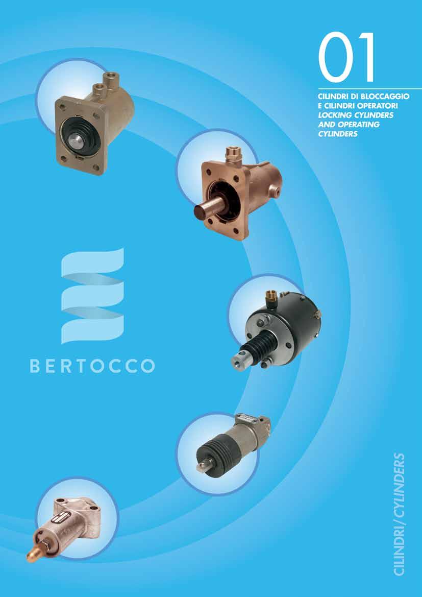
11 CILINDRI DI BLOCCGGIO E CILINDRI OPERTORI/ LOCKING CYLINDERS ND OPERTING CYLINDERS CILINDRO DI BLOCCGGIO LOCKING CYLINDER C300 (assale/axle VIBERTI) Puntale lesaggio x Corsa Interassi di fissaggio x Ø fori Push-rod Bore x Stroke Distance between fixing holes x Ø holes C Ø 28 Ø 60 x x 56 x Ø 10,5 Raccordo filettato M22x1,5/ Thread port M22x1,5 CILINDRO DI BLOCCGGIO LOCKING CYLINDER C300 Puntale lesaggio x Corsa Interassi di fissaggio x Ø fori Push-rod Bore x Stroke Distance between fixing holes x Ø holes C Ø 28 Ø 60 x x 56 x Ø 10,5 Raccordo filettato M12x1/ Thread port M12x1 CILINDRO DI BLOCCGGIO LOCKING CYLINDER C300 (assale/axle VIBERTI) Puntale lesaggio x Corsa Interassi di fissaggio x Ø fori Push-rod Bore x Stroke Distance between fixing holes x Ø holes C Ø 28 Ø 60 x x 56 x Ø 10,5 Raccordo filettato M12x1/ Thread port M12x1 CILINDRO DI BLOCCGGIO LOCKING CYLINDER C300 (assale/axle PERLINI) Puntale lesaggio x Corsa Interassi di fissaggio x Ø fori Push-rod Bore x Stroke Distance between fixing holes x Ø holes C Ø 28 Ø 60 x x 53 x Ø 10,5 Raccordo filettato M12x1/ Thread port M12x1 IR IR TRUCK TECHNOLOGY 01/5 11

12 CILINDRI DI BLOCCGGIO E CILINDRI OPERTORI/ LOCKING CYLINDERS ND OPERTING CYLINDERS CILINDRO DI BLOCCGGIO LOCKING CYLINDER C300 (assale/axle BTTGLINO) Puntale lesaggio x Corsa Interassi di fissaggio x Ø fori Push-rod Bore x Stroke Distance between fixing holes x Ø holes C Ø 28 Ø 60 x x 56 x Ø 10,5 Con raccordo per tubo Ø 6/ With fitting for pipe Ø 6 CILINDRODIBLOCCGGIO LOCKINGCYLINDER C302 (assale/axle SSERIGO) Puntale lesaggio x Corsa Interassi di fissaggio x Ø fori Push-rod Bore x Stroke Distance between fixing holes x Ø holes C Ø 25 Ø 60 x x 68 x Ø 10,5 Raccordo filettato M12x1/ Thread port M12x1 01/6 12 IR TRUCK TECHNOLOGY
13 CILINDRI DI BLOCCGGIO E CILINDRI OPERTORI/ LOCKING CYLINDERS ND OPERTING CYLINDERS CILINDRO DI BLOCCGGIO LOCKING CYLINDER C303 (assale/ axle BTTGLINO) Puntale lesaggio x Corsa Interassi di fissaggio x Ø fori Push-rod Bore x Stroke Distance between fixing holes x Ø holes C Ø 28 Ø 60 x x 54 x Ø 11,5 Raccordo filettato M12x1/ Thread port M12x1 CILINDRO DI BLOCCGGIO LOCKING CYLINDER C305 Puntale lesaggio x Corsa Interassi di fissaggio x Ø fori Push-rod Bore x Stroke Distance between fixing holes x Ø holes C Ø 22 Ø 60 x x 48 x Ø 9 Raccordo filettato M12x1/ Thread port M12x1 CILINDRO DI BLOCCGGIO LOCKING CYLINDER C305 (assale/ axle USTERS) Puntale lesaggio x Corsa Interassi di fissaggio x Ø fori Push-rod Bore x Stroke Distance between fixing holes x Ø holes C Ø 25 Ø 60 x x 68 x Ø 10,5 Raccordo filettato M12x1/ Thread port M12x1 CILINDRO DI BLOCCGGIO LOCKING CYLINDER C305 (assale/ axle STEFEN) Puntale lesaggio x Corsa Interassi di fissaggio x Ø fori Push-rod Bore x Stroke Distance between fixing holes x Ø holes C Ø 25 Ø 60 x x 68 x Ø 10,5 Raccordo filettato M12x1/ Thread port M12x1 IR IR TRUCK TECHNOLOGY 01/7 13
14 CILINDRI DI BLOCCGGIO E CILINDRI OPERTORI/ LOCKING CYLINDERS ND OPERTING CYLINDERS CILINDRO DI BLOCCGGIO LOCKING CYLINDER C305 (assale/ axle CESCHI) Puntale lesaggio x Corsa Interassi di fissaggio x Ø fori Push-rod Bore x Stroke Distance between fixing holes x Ø holes C Ø 22 Ø 60 x x 78 x Ø 9 Raccordo filettato M12x1/ Thread port M12x1 CILINDRO DI BLOCCGGIO LOCKINGCYLINDER C305 (assale/ axle CESCHI) Puntale lesaggio x Corsa Interassi di fissaggio x Ø fori Push-rod Bore x Stroke Distance between fixing holes x Ø holes C Ø 22 Ø 60 x x 78 x Ø 9 Raccordo filettato M12x1/ Thread port M12x1 01/8 14 IR TRUCK TECHNOLOGY
15 CILINDRI DI BLOCCGGIO E CILINDRI OPERTORI/ LOCKING CYLINDERS ND OPERTING CYLINDERS CILINDRO DI BLOCCGGIO (tipo inverso) LOCKING CYLINDER (inverted type) C311 (assale/ axle CESCHI) Puntale lesaggio x Corsa Interassi di fissaggio x Ø fori Push-rod Bore x Stroke Distance between fixing holes x Ø holes C Ø 22 Ø 60 x x 48 x Ø 9 Raccordo filettato M12x1/ Thread port M12x1 CILINDRO DI BLOCCGGIO (tipo inverso) LOCKING CYLINDER (inverted type) C311 Puntale lesaggio x Corsa Interassi di fissaggio x Ø fori Push-rod Bore x Stroke Distance between fixing holes x Ø holes C Ø 28 Ø 60 x x 50 x Ø 11 Raccordo filettato M12x1/ Thread port M12x1 CILINDRO DI BLOCCGGIO (tipo inverso) LOCKING CYLINDER (inverted type) C311 (assale/ axle SIRMC) Puntale lesaggio x Corsa Interassi di fissaggio x Ø fori Push-rod Bore x Stroke Distance between fixing holes x Ø holes C Ø 28 Ø 60 x x 48 x Ø 9 Raccordo filettato M16x1,5/ Thread port M16x1,5 IR IR TRUCK TECHNOLOGY 01/7 15
")
16 CILINDRI DI BLOCCGGIO E CILINDRI OPERTORI/ LOCKING CYLINDERS ND OPERTING CYLINDERS CILINDRO DI BLOCCGGIO LOCKING CYLINDER C311 Puntale lesaggio x Corsa Interassi di fissaggio x Ø fori Push-rod Bore x Stroke Distance between fixing holes x Ø holes C Ø 28 Ø 60 x x 50 x Ø 11 Con raccordo a innesto per tubo Ø 8/ With push-in fitting for pipe Ø 8 CILINDRO DI BLOCCGGIO (tipo inverso) LOCKING CYLINDER (inverted type) C311 Puntale lesaggio x Corsa Interassi di fissaggio x Ø fori Push-rod Bore x Stroke Distance between fixing holes x Ø holes C Ø 28 Ø 60 x x 48 x Ø 9 Con raccordo per tubo Ø 6/ With fitting for pipe Ø 6 CILINDRO DI BLOCCGGIO LOCKING CYLINDER C311 Puntale lesaggio x Corsa Interassi di fissaggio x Ø fori Push-rod Bore x Stroke Distance between fixing holes x Ø holes C Ø 28 Ø 60 x x 50 x Ø 11 Raccordo filettato M12x1/ Thread port M12x1 01/10 16 IR TRUCK TECHNOLOGY

17 CILINDRI DI BLOCCGGIO E CILINDRI OPERTORI/ LOCKING CYLINDERS ND OPERTING CYLINDERS CILINDRO OPERTORE OPERTING CYLINDER C315 Puntale lesaggio x Corsa Interassi di fissaggio x Ø fori Push-rod Bore x Stroke Distance between fixing holes x Ø holes C Ø 28 Ø 60 x x 56 x Ø 10,5 Raccordo filettato M12x1/ Thread port M12x1 CILINDRO MOLL per bloccaggio semirimorchi allungabili SPRING CYLINDER to lock extensible semi-trailers C317 Corsa Puntale Fissaggio viti Fissaggio interasse Stroke Push-rod Screws fixing Distance fixing C Ø 40 M16 x 1,5 120,7 Spinta molla/ spring force = corsa/ stroke 0 = 220 dan 67 = 350 dan Pressione per disattivare la molla/ Pressure to remove the spring thrust : min 2 bar Raccordo filettato M16x1,5/ Thread port M16x1,5 IR TRUCK IR TRUCK TECHNOLOGY 01/11 17
18 CILINDRI DI BLOCCGGIO E CILINDRI OPERTORI/ LOCKING CYLINDERS ND OPERTING CYLINDERS CILINDRO OPERTORE OPERTING CYLINDER C321 Estremità puntale Push-rod tip lesaggio x Corsa Bore x Stroke C foro/hole Ø 6 Ø 30 x 25 Raccordo filettato/thread port CILINDRO OPERTORE Ø 25 OPERTING CYLINDER Ø 25 C397 Estremità puntale Push-rod tip lesaggio x Corsa Bore x Stroke C M8 x 1,25 Ø 25 x 67 Raccordo filettato: M10 x 1,5/ Thread port: M10 x 1,5 01/12 18 IR TRUCK TECHNOLOGY

19 CILINDRI DI BLOCCGGIO E CILINDRI OPERTORI/ LOCKING CYLINDERS ND OPERTING CYLINDERS CILINDRO OPERTORE Ø 30 OPERTING CYLINDER Ø 30 C398 Estremità puntale Push-rod tip lesaggio x Corsa Bore x Stroke C M8 x 1,25 Ø 30 x 60 C M8 x 1,25 Ø 30 x 35 Raccordo filettato: M10 x 1/ Thread port: M10 x 1 CILINDRO OPERTORE Ø 30 OPERTING CYLINDER Ø 30 C399 Estremità puntale Push-rod tip lesaggio x Corsa Bore x Stroke C R6 sferico/spherical Ø 30 x 40 Raccordo filettato: M10 x 1/ Thread port: M10 x 1 CILINDRO OPERTORE Ø 35 OPERTING CYLINDER Ø 35 C400 Estremità puntale Push-rod tip lesaggio x Corsa Bore x Stroke C M12 x 1,5 Ø 35 x 70 Raccordo filettato: M12 x 1,5/ Thread port: M12 x 1,5 CILINDRO OPERTORE Ø 35 OPERTING CYLINDER Ø 35 C400 Estremità puntale Push-rod tip lesaggio x Corsa Bore x Stroke C M8 x 1,25 Ø 35 x 43 Raccordo filettato: M12 x 1,5/ Thread port: M12 x 1,5 IR TRUCK IR TRUCK TECHNOLOGY 01/13 19

20 CILINDRI DI BLOCCGGIO E CILINDRI OPERTORI/ LOCKING CYLINDERS ND OPERTING CYLINDERS CILINDRO OPERTORE Ø 48 OPERTING CYLINDER Ø 48 C401 Estremità puntale Push-rod tip lesaggio x Corsa Bore x Stroke C M10 x 1,25 Ø 48 x 80 C * M10 x 1,25 Ø 48 x 80 * con raccordo ruotato di 90 / with fitting 90 rotate Raccordo filettato: M12 x 1,5/ Thread port: M12 x 1,5 01/14 20 IR TRUCK TECHNOLOGY
21
22 NOTE/ NOTES 02/4 22 IR TRUCK TECHNOLOGY


23 ELEMENTI FRENNTI/ BRKE CTUTORS ELEMENTI FRENNTI - Fissaggio su basamento BRKE CTUTORS - Base mounting C403 lesaggio x Corsa Bore x Stroke Sporgenza forcella Yoke protrusion C ** Ø 75 x ** Raccordo filettato: M22 x 1,5/ Thread port: M22 x 1,5 ELEMENTI FRENNTI - Fissaggio su basamento BRKE CTUTORS - Base mounting C404 lesaggio x Corsa Bore x Stroke Sporgenza forcella Yoke protrusion C * Ø 100 x C ** Ø 100 x * Raccordo filettato: M18 x 1,5/ Thread port: M18 x 1,5 ** Raccordo filettato: M20 x 1,5/ Thread port: M20 x 1,5 ELEMENTI FRENNTI - Fissaggio su basamento BRKE CTUTORS - Base mounting C405 lesaggio x Corsa Bore x Stroke Sporgenza forcella Yoke protrusion C Ø 125 x x 175 Raccordo filettato: M22 x 1,5/ Thread port: M22 x 1,5 IR TRUCK IR TRUCK TECHNOLOGY 02/05 23
24 ELEMENTI FRENNTI/ BRKE CTUTORS ELEMENTI FRENNTI - Fissaggio su basamento BRKE CTUTORS - Base mounting C406 lesaggio x Corsa Bore x Stroke Sporgenza forcella Yoke protrusion C Ø 100 x C Ø 100 x Raccordo filettato: M22 x 1,5/ Thread port: M22 x 1,5 ttacco per tubo sbordato/fitting for flared pipe ELEMENTI FRENNTI - Fissaggio su basamento BRKE CTUTORS - Base mounting C407 lesaggio x Corsa Bore x Stroke Sporgenza forcella Yoke protrusion C Ø 125 x Raccordo filettato: M18 x 1,5/ Thread port: M18 x 1,5 02/06 24 IR TRUCK TECHNOLOGY
25 ELEMENTI FRENNTI/ BRKE CTUTORS ELEMENTI FRENNTI - Fissaggio su basamento BRKE CTUTORS - Base mounting C407 lesaggio x Corsa Bore x Stroke Sporgenza forcella Yoke protrusion C Ø 125 x Raccordo filettato: M18 x 1,5/ Thread port: M18 x 1,5 IR TRUCK IR TRUCK TECHNOLOGY 02/7 25
26 ELEMENTI FRENNTI/ BRKE CTUTORS ELEMENTI FRENNTI - Fissaggio frontale BRKE CTUTORS - Flange mounting C409 lesaggio x Corsa Bore x Stroke Sporgenza forcella Yoke protrusion C Ø 86 x Raccordo filettato: M22 x 1,5/ Thread port: M22 x 1,5 ttacco per tubo sbordato/fitting for flared pipe 02/8 26 IR TRUCK TECHNOLOGY
27 ELEMENTI FRENNTI/ BRKE CTUTORS ELEMENTI FRENNTI - Fissaggio frontale BRKE CTUTORS - Flange mounting C411 lesaggio x Corsa Bore x Stroke Sporgenza forcella Yoke protrusion C * Ø 125 x C ** Ø 125 x * Raccordo filettato: M18 x 1,5/ Thread port: M18 x 1,5 ** Raccordo filettato: M22 x 1,5/ Thread port: M22 x 1,5 ttacco per tubo sbordato/fitting for flared pipe ELEMENTI FRENNTI - Fissaggio frontale BRKE CTUTORS - Flange mounting C411 lesaggio x Corsa Bore x Stroke Sporgenza forcella Yoke protrusion C Ø 125 x Raccordo filettato: M20 x 1,5/ Thread port: M20 x 1,5 IR TRUCK IR TRUCK TECHNOLOGY 02/9 27

28 ELEMENTI FRENNTI/ BRKE CTUTORS ELEMENTI FRENNTI - Fissaggio frontale BRKE CTUTORS - Flange mounting C411 lesaggio x Corsa Bore x Stroke Sporgenza forcella Yoke protrusion C Ø 125 x Raccordo filettato: M22 x 1,5/ Thread port: M22 x 1,5 ttacco per tubo sbordato/fitting for flared pipe 02/10 28 IR TRUCK TECHNOLOGY
29
30 NOTE/ NOTES 03/4 30 IR TRUCK TECHNOLOGY
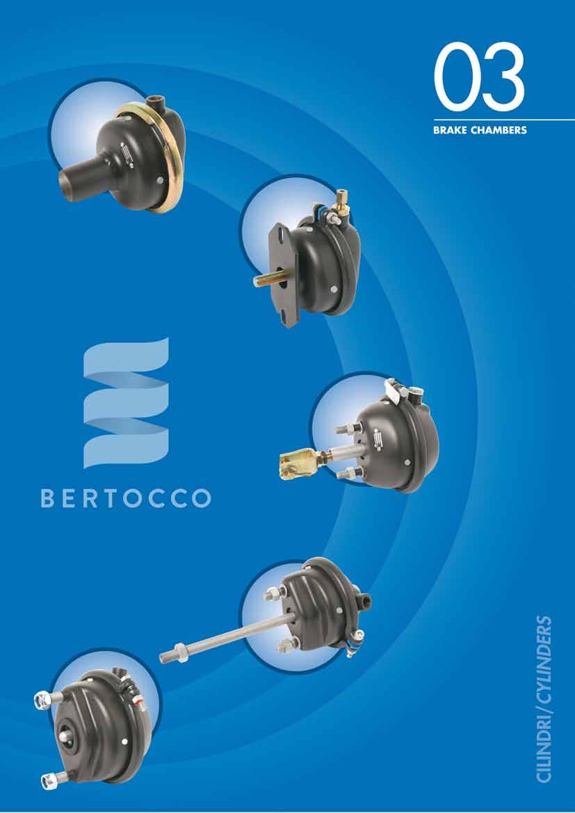
31 BRKE CHMBERS BRKE CHMBER TIPO 7 (per freni a cuneo) BRKE CHMBER TYPE 7 (for wedge brake) C418 Filettatura Lunghezza Corsa Thread Length Stroke C M48 x Raccordo filettato: M16 x 1,5/ Thread port: M16 x 1,5 ice membrana/ Diaphragm cod : BRKE CHMBER TIPO 10.5 (per freni a cuneo) BRKE CHMBER TYPE 10.5 (for wedge brake) C419 Filettatura Lunghezza Corsa Thread Length Stroke C / C / C / C M48 x C M48 x C M48 x C M48 x Raccordo filettato: M16 x 1,5/ Thread port: M16 x 1,5 ice membrana/ Diaphragm cod : BRKE CHMBER TIPO 9 (per freni a cuneo) BRKE CHMBER TYPE 9 (for wedge brake) C422 Filettatura Lunghezza Corsa Thread Length Stroke C / C / C / C M48 x Raccordo filettato: M16 x 1,5/ Thread port: M16 x 1,5 ice membrana/ Diaphragm cod : BRKE CHMBER TIPO 12 (per freni a cuneo) BRKE CHMBER TYPE 12 (for wedge brake) C424 Filettatura Lunghezza Corsa Thread Length Stroke C / C / C / C M48 x C M48 x Raccordo filettato: M16 x 1,5/ Thread port: M16 x 1,5 ice membrana/ Diaphragm cod : IR TRUCK IR TRUCK TECHNOLOGY 03/5 31
32 BRKE CHMBERS BRKE CHMBER TIPO 9 (per bloccaggio assale sterzante) BRKE CHMBER TYPE 9 (for locking steering axle) C423 Blocchetto/Block Corsa Dimensione Stroke Dimension C * x 70 x C ** x 70 x ice membrana/ Diaphragm cod : * Raccordo filettato: M16 x 1,5/ Thread port: M16 x 1,5 ** Con raccordo per tubo Ø 6/ With fitting for pipe Ø 6 BRKE CHMBER TIPO 9 (per bloccaggio assale sterzante) BRKE CHMBER TYPE 9 (for locking steering axle) C423 Blocchetto/Block Corsa Dimensione Stroke Dimension C x 60 x ice membrana/ Diaphragm cod : Con raccordo per tubo Ø 6/ With fitting for pipe Ø 6 BRKE CHMBER TIPO 9 (per bloccaggio assale sterzante) BRKE CHMBER TYPE 9 (for locking steering axle) C423 C C senza blocchetto con asta filettata M14x1,5 without block, with thread rod M14x1,5 senza blocchetto con asta filettata M16x1,5 without block, with thread rod M16x1,5 Corsa Stroke ice membrana/ Diaphragm cod : Con raccordo per tubo Ø 6/ With fitting for pipe Ø 6 03/6 32 IR TRUCK TECHNOLOGY

33 BRKE CHMBERS BRKE CHMBER TIPO 9 (per bloccaggio assale sterzante) BRKE CHMBER TYPE 9 (for locking steering axle) C423 Blocchetto/ Block Corsa Dimensione Stroke Dimension C * x 70 x ** Con piastra di fissaggio sagomata/ With formed mounting plate Raccordo filettato: M16 x 1,5/ Thread port: M16 x 1,5 ice membrana/ Diaphragm cod : BRKE CHMBER TIPO 9 (per bloccaggio assale sterzante) BRKE CHMBER TYPE 9 (for locking steering axle) C423 Blocchetto/ Block Corsa Dimensione Stroke Dimension C * x 70 x Raccordo filettato: M12 x 1/ Thread port: M12 x 1 ice membrana/ Diaphragm cod : BRKE CHMBER TIPO 12 (per freni a camma) con puntale registrabile per rimorchi agricoli BRKE CHMBER TYPE 12 (for S cam brake) with adjustable push-rod for agricoltural trailer C427 Forcella/Yoke Fissaggio/Fixing Corsa Dimensione Viti Interasse Stroke Dimension Screws Distance C * * M12 x 1,75 76,2 C Ø 12, M12 x 1,75 76,2 * Senza forcella/ Without yoke Raccordi filettati: M16 x 1,5/ Thread ports: M16 x 1,5 ice membrana/ Diaphragm cod : BRKE CHMBER TIPO 16 (per freni a camma) con puntale registrabile per rimorchi agricoli BRKE CHMBER TYPE 16 (for S cam brake) with adjustable push-rod for agricoltural trailer C437 Forcella/Yoke Fissaggio/Fixing Corsa Dimensione Viti Interasse Stroke Dimension Screws Distance C * * M12 x 1,75 76,2 C Ø 12, M12 x 1,75 76,2 * Senza forcella/ Without yoke Raccordi filettati: M16 x 1,5/ Thread ports: M16 x 1,5 ice membrana/ Diaphragm cod : IR TRUCK IR TRUCK TECHNOLOGY 03/7 33


34 BRKE CHMBERS BRKE CHMBER (per freni a camma) corsa 57 BRKE CHMBER (for S cam brake) stroke 57 C473 Fissaggio/Fixing Tipo Viti Interasse Lungh. asta membrana Type Screws Distance Rod lenght Diaphragm cod C M16 x 1,5 120, C M16 x 1,5 120, Raccordi filettati: M16 x 1,5/ Thread ports: M16 x 1,5 BRKE CHMBER (per freni a camma) corsa 57 BRKE CHMBER (for S cam brake) stroke 57 C473 Fissaggio/Fixing Tipo Viti Interasse Lungh. asta Type Screws Distance Rod lenght C M16 x 1,5 120,7 190 ice membrana/ Diaphragm cod : Raccordi filettati: M16 x 1,5/ Thread ports: M16 x 1,5 BRKE CHMBER TIPO 9 (per freni a camma) corsa 48 BRKE CHMBER TYPE 9 (for S cam brake) stroke 48 C474 Fissaggio/Fixing Viti Interasse Lungh. asta Screws Distance Rod lenght C M12 x 1,75 76,2 190 ice membrana/ Diaphragm cod : Raccordi filettati: M16 x 1,5/ Thread ports: M16 x 1,5 03/8 34 IR TRUCK TECHNOLOGY

35 BRKE CHMBERS BRKE CHMBER TIPO 12 (per freni a camma) corsa 78 BRKE CHMBER TYPE 12 (for S cam brake) stroke 78 C474 Fissaggio/Fixing Forcella/Yoke Viti Interasse Sporgenza Dimensioni Screws Distance Protrusion Dimensions C M12 x 1,75 76,2 193 C M12 x 1,75 76,2 244 Ø C M12 x 1,75 76,2 299 Ø 14 ** C M12 x 1,75 76,2 244 Ø 12, C M12 x 1,75 76,2 160 ** Forcella asolata/ Oblong yoke Raccordi filettati M16x1,5/Thread ports M16x1,5 ice membrana/ Diaphragm cod : BRKE CHMBER TIPO 14 (per freni a camma) corsa 75 BRKE CHMBER TYPE 14 (for S cam brake) stroke 75 C474 Fissaggio/Fixing Forcella/Yoke Viti Interasse Sporgenza Dimensioni Screws Distance Protrusion Dimensions C M16 x 1,5 120,7 200 C M16 x 1,5 120,7 256 Ø Raccordi filettati: M16 x 1,5/ Thread ports: M16 x 1,5 ice membrana/ Diaphragm cod: BRKE CHMBER TIPO 16 (per freni a camma) corsa 75 BRKE CHMBER TYPE 16 (for S cam brake) stroke 75 C474 Fissaggio/Fixing Forcella/Yoke Viti Interasse Sporgenza Dimensioni Screws Distance Protrusion Dimensions C M12x1,5 76,2 200 C M12x1,5 76,2 256 Ø C M12x1,5 76,2 300 Ø 14* C M12x1,5 76,2 256 Ø 12, C M12x1,5 120,7 56 C M12x1,5 76,2 156 Ø C M12x1,5 76,2 200 C M12x1,5 76,2 256 Ø * Forcella asolata/ Oblong yoke ice membrana/ Diaphragm cod: Raccordi filettati/thread ports: M16 x 1,5 IR TRUCK IR TRUCK TECHNOLOGY 03/9 35

36 BRKE CHMBERS BRKE CHMBER TIPO 20 (per freni a camma) corsa 75 BRKE CHMBER TYPE 20 (for S cam brake) stroke 75 C474 Forcella/Yoke Sporgenza Dimensioni Protrusion Dimensions ice membrana/ Diaphragm cod : C C Ø C Ø 14* C Ø 12, C Ø 12, C Ø * Forcella asolata/ Oblong yoke Raccordi filettati: M16 x 1,5/ Thread ports: M16 x 1,5 BRKE CHMBER TIPO 24 (per freni a camma) corsa 75 BRKE CHMBER TYPE 24 (for S cam brake) stroke 75 C474 Forcella/Yoke Sporgenza Dimensioni Protrusion Dimensions ice membrana/ Diaphragm cod : C C Ø C Ø 14* C Ø 12, C C Ø * Forcella asolata/ Oblong yoke Raccordi filettati: M16 x 1,5/ Thread ports: M16 x 1,5 BRKE CHMBER TIPO 30 (per freni a camma) corsa 75 BRKE CHMBER TYPE 30 (for S cam brake) stroke 75 C474 Forcella/Yoke Sporgenza Dimensioni Protrusion Dimensions ice membrana/ Diaphragm cod : C C Ø C Ø 14* C Ø 12, C C Ø C Ø * Forcella asolata/ Oblong yoke Raccordi filettati: M16 x 1,5/ Thread ports: M16 x 1,5 BRKE CHMBER TIPO 36 (per freni a camma) corsa 75 BRKE CHMBER TYPE 36 (for S cam brake) stroke 75 C474 Forcella/Yoke Sporgenza Dimensioni Protrusion Dimensions ice membrana/ Diaphragm cod : C C Ø C Ø 14* C Ø 12, C ** 150 Ø * Forcella asolata/ Oblong yoke ** Con raccordo a innesto T8x1/ With push-in fitting T8x1 Raccordi filettati : M16 x 1,5/ Thread ports: M16 x 1,5 03/10 36 IR TRUCK TECHNOLOGY
37 BRKE CHMBERS BRKE CHMBER (per freni a disco) BRKE CHMBER (for air disc brake) C475 Tipo Corsa membrana Type Stroke Diaphragm cod C C C C C C C C Raccordo filettato: M16 x 1,5/ Thread port: M16 x 1,5 BRKE CHMBER (per freni a disco Elsa 2 ) BRKE CHMBER (for Elsa 2 air disc brake) C480 con sporgenza puntale 20 mm/ with 20 mm push-rod protrusion Tipo Corsa membrana Type Stroke Diaphragm cod C C C C C C C C Raccordo filettato: M16 x 1,5/ Thread port: M16 x 1,5 IR TRUCK IR TRUCK TECHNOLOGY 03/11 37
38 NOTE/ NOTES 03/4 38 IR TRUCK TECHNOLOGY

39
40 NOTE/ NOTES 04/4 40 IR TRUCK TECHNOLOGY

41 BIELEMENTI FRENNTI/ SPRING BRKE CTUTORS BIELEMENTI FRENNTI (per freni a disco) membrana/stantuffo SPRING BRKE CTUTORS (for air disc brake) diaphragm/piston C476 Servizio/Service Stazionamento/Parking Tipo Corsa Tipo Corsa Type Stroke Type Stroke C C C C C Raccordi filettati: M16 x 1,5/ Thread ports: M16 x 1,5 BIELEMENTI FRENNTI (per freni a disco) membrana/membrana SPRING BRKE CTUTORS (for air disc brake) diaphragm/diaphragm C477 Servizio/Service Stazionamento/Parking Tipo Corsa Tipo Corsa Type Stroke Type Stroke C C C C C Raccordi filettati: M16 x 1,5/ Thread ports: M16 x 1,5 BIELEMENTI FRENNTI (per freni a disco Elsa 2 ) membrana/membrana SPRING BRKE CTUTORS (for Elsa 2 air disc brake) diaphragm/diaphragm C480 con sporgenza puntale 20 mm/ with 20 mm push-rod protrusion Servizio/Service Stazionamento/Parking Tipo Corsa Tipo Corsa Type Stroke Type Stroke C HF* 75 C HF* 75 C HF* 75 C HF* 75 C HF* 75 C HF* 75 C HF* 75 * HF = high force Raccordi filettati/thread ports: M16 x 1,5 IR TRUCK IR TRUCK TECHNOLOGY 04/5 41


42 BIELEMENTI FRENNTI/ SPRING BRKE CTUTORS BIELEMENTI FRENNTI (per freni a camma) membrana/membrana SPRING BRKE CTUTORS (for S cam brake) diaphragm/diaphragm C479 Servizio/Service Stazionamento/Parking Tipo Corsa Tipo Corsa Type Stroke Type Stroke C C C C C Raccordi filettati: M16 x 1,5/ Thread ports: M16 x 1,5 BIELEMENTI FRENNTI (per freni a camma) membrana/membrana SPRING BRKE CTUTORS (for S cam brake) diaphragm/diaphragm C481 Servizio/Service Stazionamento/Parking Tipo Corsa Tipo Corsa Type Stroke Type Stroke C C * C ** * Senza forcella con raccordi a innesto T8x1/ Without yoke and with push-in fitting for pipe T8x1 ** Con asta L=250/ With 250 mm push-rod length Raccordi filettati: M16 x 1,5/ Thread ports: M16 x 1,5 BIELEMENTI FRENNTI (per freni a camma) membrana/stantuffo SPRING BRKE CTUTORS (for S cam brake) diaphragm/piston C48x 5000 Servizio/Service Stazionamento/Parking Tipo Corsa Tipo Corsa Type Stroke Type Stroke C C C C C Raccordi filettati: M16 x 1,5/ Thread ports: M16 x 1,5 04/6 42 IR TRUCK TECHNOLOGY

 membrana/stantuffo SPRING BRKE CTUTORS (for wedge brake) diaphragm/piston C492 Tipo Filettatura Lunghezza Corsa Type Thread Length Stroke C492")
43 BIELEMENTI FRENNTI/ SPRING BRKE CTUTORS BIELEMENTI FRENNTI (per freni a cuneo) membrana/stantuffo SPRING BRKE CTUTORS (for wedge brake) diaphragm/piston C491 con flangia di fissaggio/ with fixing flange Tipo Lunghezza Corsa Type Length Stroke C / /53 C * 9/ /53 C / /53 C * 16/ /53 Con raccordi Voss/ With Voss fittings * Con flangia ruotata di 180 / With 180 deg. rotate flange BIELEMENTI FRENNTI (per freni a cuneo) membrana/stantuffo SPRING BRKE CTUTORS (for wedge brake) diaphragm/piston C492 Tipo Filettatura Lunghezza Corsa Type Thread Length Stroke C /24 M45 x 1, /57 Raccordi filettati: M16 x 1,5/ Thread port: M16 x 1,5 BIELEMENTI FRENNTI (per freni a cuneo) membrana/stantuffo SPRING BRKE CTUTORS (for wedge brake) diaphragm/piston C493 tipo/ type 10,5 /6200 Filettatura Lunghezza Corsa Thread Length Stroke C / C / C / C M48 x C M48 x C M48 x Raccordi filettati: M16 x 1,5/ Thread port: M16 x 1,5 BIELEMENTI FRENNTI (per freni a cuneo) membrana/stantuffo SPRING BRKE CTUTORS (for wedge brake) diaphragm/piston C494 tipo/ type 12 /6200 Filettatura Lunghezza Corsa Thread Length Stroke C / C / C M48 x C M48 x C * 1 3/ * Versione/ Version 12 /7400 Raccordi filettati: M16 x 1,5/ Thread port: M16 x 1,5 IR TRUCK IR TRUCK TECHNOLOGY 04/7 43
44 NOTE/ NOTES 04/4 44 IR TRUCK TECHNOLOGY
45


46 CONVERTITORI PNEUMOIDRULICI/ IR OVER HYDRULIC CYLINDERS CONVERTITORE PNEUMOIDRULICO IR OVER HYDRULIC CYLINDER C500 - C502 lesaggio x corsa Bore x Stroke C Ø 180 x ,47 cm C Ø 200 x ,16 cm Con interruttore unipolare 24Vcc/ With unipolar switch 24Vdc Raccordo filettato: M20 x 1,5/ Thread port: M20 x 1,5 POMP IDRULIC HYDRULIC PUMP H860 lesaggio x corsa Bore x Stroke H Ø 44,45 x cm Per impiego con liquido freni/ For braking fluid use Raccordo filettato: M12 x 1,5/ Thread port: M12 x 1,5 05/4 46 IR TRUCK TECHNOLOGY
47
48 NOTE/ NOTES 06/4 48 IR TRUCK TECHNOLOGY

49 DEVITORI/ VLVES DEVITORE 1 SEZIONE ONE - WY VLVE D101 - Raccordi filettati : M12 x 1,25/ Thread port: M12 x 1,25 D versione base/ standard version D con coperchio tagliato/ with cut cover D con coperchio tagliato e con indicatore di pressione N with cut cover and NO pressure switch D completo di indicatore di pressione N e spia with NO pressure switch and warning lamp D completo di indicatore di pressione NC e spia with NC pressure switch and warning lamp D * completo di indicatore di pressione N e spia with NO pressure switch and warning lamp Con puntale in ottone/with brass push-rod N = contatti normalmente aperti NO = contacts normally open NC = contatti normalmente chiusi NC = contacts normally closed D101 - Raccordi filettati : G1/8 / Thread port: G1/8 D versione base/ standard version D con coperchio tagliato/ with cut cover D completo di indicatore di pressione N e spia complete of pressure switch NO and warning lamp DEVITORE 1 SEZIONE ONE - WY VLVE D101 con cuffia in gomma/ with rubber cover D * D *** D ** con coperchio tagliato/ with cut cover completo di indicatore di pressione N e spia with NO pressure switch and warning lamp con coperchio tagliato/ with cut cover * Raccordi filettati: M12 x 1,25/ Thread ports: M12 x 1,25 ** Raccordi filettati: G1/8/ Thread ports: G1/8 *** Completo di raccordi: 1 = raccordo diritto T8 2 = raccordo gomito T8 With fittings: 1 = straight fitting T8 2 = elbow fitting T8 N = contatti normalmente aperti NO = contacts normally open IR TRUCK IR TRUCK TECHNOLOGY 06/5 49

50 DEVITORI/ VLVES DEVITORE 2 SEZIONI DOUBLE ONE - WY VLVE D102 - Raccordi filettati: : M12 x 1,25/ Thread port: M12 x 1,25 D D D D versione base/ standard version con coperchio tagliato/ with cut cover con coperchio tagliato e con indicatore di pressione N with cut cover and NO pressure switch completo di indicatore di pressione N e spia with NO pressure switch and warning lamp N = contatti normalmente aperti NO = contacts normally open D102 - Raccordi filettati: G1/8 / Thread port: G1/8 D D D versione base/ standard version completo di indicatore di pressione N e spia with NO pressure switch and warning lamp con coperchio tagliato/ with cut cover DEVITORE 3 SEZIONI TRIPLE ONE - WY VLVE D103 - Raccordi filettati: M12 x 1,25/ Thread port: M12 x 1,25 D D D D D * versione base/ standard version con coperchio tagliato/ with cut cover con coperchio tagliato e con indicatore di pressione N with cut cover and NO pressure switch completo di indicatore di pressione N e spia with NO pressure switch and warning lamp completo di indicatore di pressione N e spia with NO pressure switch and warning lamp Con puntale in ottone/with brass push-rod D103 - Raccordi filettati: G1/8 / Thread port: G1/8 D D D versione base/ standard version con coperchio tagliato/ with cut cover completo di indicatore di pressione N e spia with NO pressure switch and warning lamp 06/6 50 IR TRUCK TECHNOLOGY
51 DEVITORI/ VLVES DEVITORE 4 SEZIONI QUDRUPLE ONE - WY VLVE D104 - Raccordi filettati: M12 x 1,25/ Thread port: M12 x 1,25 D D D D * versione base/ standard version con coperchio tagliato/ with cut cover completo di indicatore di pressione N e spia with NO pressure switch and warning lamp completo di indicatore di pressione N e spia with NO pressure switch and warning lamp Con puntale in ottone/with brass push-rod N = contatti normalmente aperti NO = contacts normally open IR TRUCK IR TRUCK TECHNOLOGY 06/7 51

52 DEVITORI/ VLVES DEVITORI D CRUSCOTTO DOUBLE ONE-WY VLVES FOR DSH BORD D121 - Raccordi filettati: G1/8 / Thread port: G1/8 1 D deviatore a 2 sezioni/ double one-way valve La ghiera viene fornita separatamente The nut is sold separately D deviatore a 2 sezioni/ double one-way valve D deviatore a 1 sezione/ one-way valve GHIERE DI BLOCCGGIO PER DEVITORI D CRUSCOTTO - M28X1,5 LOCKING NUT VLVES FOR DSH BORD /8 52 IR TRUCK TECHNOLOGY


53 DEVITORI/ VLVES DEVITORI 1 SEZIONE con fissaggio sul corpo ONE-WY VLVE fixing on the body D130 Simbolo Funzione Senza indicatore Con indicatore e spia * Symbol Employ Without pressure gauge With warning light and pres. gauge M12x1,25 G1/8 M12x1,25 G1/8 presa di forza power take off blocc. sterzante steering axle locking ribaltabile tipping sollevamento assale axle lifting discesa lenta slow lowering D D D D D D D D D D D D D D D D D D D D * N = contatti normalmente aperti NO = contacts normally open discesa veloce quick lowering D D D D DEVITORI 1 SEZIONE con fissaggio sul coperchio ONE-WY VLVE fixing on the cover D130 Simbolo Funzione Senza indicatore Con indicatore e spia * Symbol Employ Without pressure gauge With warning light and pres. gauge M12x1,25 G1/8 M12x1,25 G1/8 presa di forza power take off blocc. sterzante steering axle locking ribaltabile tipping sollevamento assale axle lifting discesa lenta slow lowering D D D D D D D D D D D D D D D D D D D D * N = contatti normalmente aperti NO = contacts normally open discesa veloce quick lowering D D D D IR TRUCK IR TRUCK TECHNOLOGY 06/9 53


54 DEVITORI/ VLVES DEVITORI 2 SEZIONI con fissaggio sul corpo DOUBLE ONE-WY VLVE fixing on the body D132 * N = contatti normalmente aperti NO = contacts normally open Simbolo Funzione Senza indicatore Con indicatore e spia * Symbol Employ Without pressure gauge With warning light and pres. gauge presa di forza power take off ribaltabile tipping blocc. sterzante steering axle locking sollevamento assale axle lifting M12x1,25 G1/8 M12x1,25 G1/8 D D D D D D D D DEVITORI 2 SEZIONI con fissaggio sul coperchio DOUBLE ONE-WY VLVE fixing on the cover D132 * N = contatti normalmente aperti NO = contacts normally open Simbolo Funzione Senza indicatore Con indicatore e spia * Symbol Employ Without pressure gauge With warning light and pres. gauge presa di forza power take off ribaltabile tipping blocc. sterzante steering axle locking sollevamento assale axle lifting M12x1,25 G1/8 M12x1,25 G1/8 D D D D D D D D DEVITORI 3 SEZIONI con fissaggio sul corpo TRIPLE ONE-WY VLVE fixing on the body D133 Simbolo Funzione Senza indicatore Con indicatore e spia * Symbol Employ Without pressure gauge With warning light and pres. gauge presa di forza power take off M12x1,25 G1/8 M12x1,25 G1/8 ribaltabile tipping D D D D * N = contatti normalmente aperti NO = contacts normally open discesa lenta slow lowering DEVITORI 3 SEZIONI con fissaggio sul coperchio TRIPLE ONE-WY VLVE fixing on the cover D133 Simbolo Funzione Senza indicatore Con indicatore e spia * Symbol Employ Without pressure gauge With warning light and pres. gauge presa di forza power take off M12x1,25 G1/8 M12x1,25 G1/8 ribaltabile tipping D D D D * N = contatti normalmente aperti NO = contacts normally open discesa lenta slow lowering 06/10 54 IR TRUCK TECHNOLOGY
55 DEVITORI/ VLVES DEVITORE 1 SEZIONE CON FISSGGIO PER FORO Ø 26 ONE-WY VLVE FIXING WITH HOLE Ø 26 D136 D raccordi filettati G1/8 / Thread port G1/8 D raccordi filettati M12 x 1,25/ Thread port M12 x 1,25 IR TRUCK IR TRUCK TECHNOLOGY 06/11 55
56 NOTE/ NOTES 06/4 56 IR TRUCK TECHNOLOGY

57


58 DISTRIBUTORI PER RIBLTBILI/ DISTRIBUTOR VLVES FOR DUMPERS DISTRIBUTORE 2 SEZIONI 2 WY DISTRIBUTOR VLVES D125 - senza ritorno automatico della leva/ without automatic lever return D D * D125 - con ritorno automatico della leva sezione 21-Low e sezione 22-Tip with automatic lever return in reset position for Tip function D D * D125 - con ritorno automatico della leva sezione 22-Tip with automatic return lever in reset position for Tip function D D * * Con indicatore di pressione e spia/ With pressure switch and warning lamp Raccordi filettati: G1/8 / Thread ports: G1/8 DISTRIBUTORE 3 SEZIONI 3 WY DISTRIBUTOR VLVES D126 - senza ritorno automatico della leva/ without automatic lever return D D # D * D *# * Con indicatore di pressione e spia With pressure switch and warning lamp # Con disinserimento automatico della sezione 23-PTO durante l azionamento della sezione 21-Low With automatic disengagement of section 23 (PTO) while activaiting section 21 D126 - D D # D * D *# con ritorno automatico della leva sezione 21-Low e sezione 22-Tip with automatic lever return in reset position for Low and Tip functions Raccordi filettati: G1/8 Thread ports: G1/8 D126 - con ritorno automatico della leva sezione 22-Tip with automatic lever return in reset position for Tip function D D # D * D *# 07/4 58 IR TRUCK TECHNOLOGY
59 DISTRIBUTORI PER RIBLTBILI/ DISTRIBUTOR VLVES FOR DUMPERS DISTRIBUTORE 2 SEZIONI 2 WY DISTRIBUTOR VLVES D135 - senza ritorno automatico della leva sezione 21-Low e 22-Tip in posizione di riposo without automatic return lever in reset position port 21-Low and 22-Tip D / 24V * D / 12V * D / 24V D / 24V # D / 12V # Con indicatore luminoso With warning lamp D * Senza indicatore luminoso/without warning lamp D135 - con ritorno automatico della leva sezione 21-Low e 22-Tip in posizione di riposo with automatic return lever in reset position port 21-Low and 22-Tip D / 24V * D / 16V * D / 24V # D / 12V # * Raccordi automatici T6x1 utomatic fittings # Raccordi automatici T1/4 utomatic fittings Raccordi filettati: G1/8 Thread ports: G1/8 DISTRIBUTORE 3 SEZIONI 3 WY DISTRIBUTOR VLVES D137 - senza ritorno automatico della leva sezione 21-Low e 22-Tip in posizione di riposo without automatic return lever in reset position port 21-Low and 22-Tip D / 24V * D / 12V D / 24V # D / 12V * D / 12V # D / 24V * D / 24V # D / 12V * D / 12V # Durante l abbassamento del cassone (azionametno della sezione LOW) viene automaticamente disinserita la presa di forza (sezione PTO) When the vehicle s body is lowering (by LOW control section) automatically the power take off (PTO) is switched off. Durante l abbassamento del cassone (azionametno della sezione LOW) non viene automaticamente disinserita la presa di forza (sezione PTO) When the vehicle s body is lowering (by LOW control section) the power take off (PTO) isn t automatically switched off. Con indicatore luminoso With warning lamp D137 - con ritorno automatico della leva sezione 21-Low e 22-Tip in posizione di riposo with automatic return lever in reset position port 21-Low and 22-Tip D / 24V * D / 24V # D / 12V * D / 12V # D / 24V * D / 24V # D / 12V * D / 12V # Durante l abbassamento del cassone (azionametno della sezione LOW) viene automaticamente disinserita la presa di forza (sezione PTO) When the vehicle s body is lowering (by LOW control section) automatically the power take off (PTO) is switched off Durante l abbassamento del cassone (azionametno della sezione LOW) non viene automaticamente disinserita la presa di forza (sezione PTO) When the vehicle s body is lowering (by LOW control section) the power take off (PTO) isn t automatically switched off. * Raccordi automatici T6x1 utomatic fittings # Raccordi automatici T1/4 utomatic fittings Raccordi filettati: G1/8 Thread ports: G1/8 IR TRUCK TECHNOLOGY 59
60 DISTRIBUTORI PER RIBLTBILI/ DISTRIBUTOR VLVES FOR DUMPERS DISTRIBUTORE 2 SEZIONI 2 WY DISTRIBUTOR VLVES D138 - controllo del ribaltabile con arresto sulle sezioni Tip e Low dumper hand control valve with lever stop on Tip and Low position D * D # * Raccordi filettati M10x1 posizionati sul fianco/ Thread ports M10x1 on the side face # Raccordi filettati G1/8 posizionati sulla faccia inferiore/ Thread ports G1/8 on the bottom face DISTRIBUTORE 2 SEZIONI con ritorno automatico della leva 2 WY DISTRIBUTOR VLVES D138 - controllo del ribaltabile con arresto autom. nella posizione di stop dumper hand control valve with automatic lever return in stop position D Raccordi filettati G1/8 posizionati sulla faccia inferiore/ Thread ports G1/8 on the bottom face DEVITORE 1 SEZIONE - manopola ONE-WY VLVE - selector D138 - per inserimento della presa di forza for power take-off engagement control D * D # * Raccordi filettati M10x1 posizionati sul fianco/ Thread ports M10x1 on the side face # Raccordi filettati G1/8 posizionati sulla faccia inferiore/ Thread ports G1/8 on the bottom face DEVITORE 1 SEZIONE - manopola ONE-WY VLVE - selector D138 - per selezionare impianto motrice-rimorchio for selection of truck-trailer system D * D # * Raccordi filettati M10x1 posizionati sul fianco/ Thread ports M10x1 on the side face # Raccordi filettati G1/8 posizionati sulla faccia inferiore/ Thread ports G1/8 on the bottom face 07/6 60 IR TRUCK TECHNOLOGY
61 DISTRIBUTORI PER RIBLTBILI/ DISTRIBUTOR VLVES FOR DUMPERS DEVITORE 1 SEZIONE - pulsante ONE-WY VLVE - button D138 - per inserimento della presa di forza for power take-off engagement control D * D ** * Raccordi filettati M10x1 posizionati sul fianco/ Thread ports M10x1 on the side face # Raccordi filettati G1/8 posizionati sulla faccia inferiore/ Thread ports G1/8 on the bottom face DEVITORE 2 SEZIONI - manopola DOUBLE ONE-WY VLVES - selector D138 - per controllo aprisponde laterali for control valve with side board control D * D ** * Raccordi filettati M10x1 posizionati sul fianco/ Thread ports M10x1 on the side face # Raccordi filettati G1/8 posizionati sulla faccia inferiore/ Thread ports G1/8 on the bottom face DEVITORE 2 SEZIONI - pulsante DOUBLE ONE-WY VLVES - button D138 - per controllo aprisponde laterali for control valve with side board control D * D ** * Raccordi filettati M10x1 posizionati sul fianco/ Thread ports M10x1 on the side face # Raccordi filettati G1/8 posizionati sulla faccia inferiore/ Thread ports G1/8 on the bottom face IR TRUCK IR TRUCK TECHNOLOGY 07/7 61


62 DISTRIBUTORI PER RIBLTBILI/ DISTRIBUTOR VLVES FOR DUMPERS DISTRIBUTORE SSEMBLTO SSEMBLED DISTRIBUTOR VLVE D138 - controllo del ribaltabile e inserimento della presa di forza dumper hand control valve with power take-off engagement control D * D ** * Raccordi filettati M10x1 posizionati sul fianco/ Thread ports M10x1 on the side face # Raccordi filettati G1/8 posizionati sulla faccia inferiore/ Thread ports G1/8 on the bottom face DISTRIBUTORE SSEMBLTO SSEMBLED DISTRIBUTOR VLVE D138 - controllo del ribaltabile e controllo aprisponde laterali dumper hand control valve with side board control D * D ** * Raccordi filettati M10x1 posizionati sul fianco/ Thread ports M10x1 on the side face # Raccordi filettati G1/8 posizionati sulla faccia inferiore/ Thread ports G1/8 on the bottom face DISTRIBUTORE SSEMBLTO SSEMBLED DISTRIBUTOR VLVE D138 - controllo del ribaltabile, inserimento della presa di forza e controllo aprisponde laterali dumper hand control valve, with power take-off engagement control and side board control D * D ** * Raccordi filettati M10x1 posizionati sul fianco/ Thread ports M10x1 on the side face # Raccordi filettati G1/8 posizionati sulla faccia inferiore/ Thread ports G1/8 on the bottom face DISTRIBUTORE SSEMBLTO SSEMBLED DISTRIBUTOR VLVE D138 - controllo del ribaltabile, inserimento della presa di forza e controllo aprisponde laterali dumper hand control valve, with power take-off engagement control and side board control D * * Raccordi filettati G1/8 posizionati sulla faccia inferiore/ Thread ports G1/8 on the bottom face 07/8 62 IR TRUCK TECHNOLOGY
63 DISTRIBUTORI PER RIBLTBILI/ DISTRIBUTOR VLVES FOR DUMPERS DISTRIBUTORE 2 SEZIONI 2 WY DISTRIBUTOR VLVES D143 - senza ritorno automatico della leva sezione 21-Low e 22-Tip in posizione di riposo without automatic return lever in reset position port 21-Low and 22-Tip D / 24V D / 24V * D / 24V # D143 - con ritorno automatico della leva sezione 21-Low e 22-Tip in posizione di riposo with automatic return lever in reset position port 21-Low and 22-Tip Senza indicatore luminoso Withou warning lamp D / 24V D / 24V * D / 24V # D143 - con ritorno automatico della leva solo sezione 22-Tip in posizione di riposo with automatic return lever in reset position port 22-Tip D / 24V D / 24V * D / 24V # * Raccordi automatici T6x1 utomatic fittings # Raccordi automatici T1/4 utomatic fittings Raccordi filettati: G1/8 Thread ports: G1/8 IR TRUCK TECHNOLOGY 63
64 DISTRIBUTORI PER RIBLTBILI/ DISTRIBUTOR VLVES FOR DUMPERS DISTRIBUTORE 3 SEZIONI 3 WY DISTRIBUTOR VLVES D144 - senza ritorno automatico della leva sezione 21-Low e 22-Tip in posizione di riposo without automatic return lever in reset position port 21-Low and 22-Tip D * D D # Con indicatore luminoso With warning lamp D144 - con ritorno automatico della leva sezione 21-Low e 22-Tip in posizione di riposo with automatic return lever in reset position port 21-Low and 22-Tip Tensione di esercizio 24V cc Operating voltage D * D D # * Raccordi automatici T6x1 utomatic fittings # Raccordi automatici T1/4 utomatic fittings Raccordi filettati: G1/8 Thread ports: G1/8 D144 - con ritorno automatico solo sezione 22-Tip in posizione di riposo with automatic return lever in reset position port 22-Tip D * D D # Durante l abbassamento del cassone (azionametno della sez. LOW) viene automaticamente disinserita la presa forza (sez. PTO). When the vehicle s body is lowering (by LOW control section) automatically the power take off (PTO) is switched off. D144 - senza ritorno automatico della leva sezione 21-Low e 22-Tip in posizione di riposo without automatic return lever in reset position port 21-Low and 22-Tip D D * D # D144 - con ritorno automatico solo sezione 22-Tip in posizione di riposo with automatic return lever in reset position port 22-Tip D D * D # D144 - con ritorno automatico della leva sezione 21-Low e 22-Tip in posizione di riposo with automatic return lever in reset position port 21-Low and 22-Tip D D * D # Durante l abbassamento del cassone (azionametno della sez. LOW) non viene automaticamente disinserita la presa forza (sez. PTO). When the vehicle s body is lowering (by LOW control section) the power take off (PTO) isn t automatically switched off. 64 IR TRUCK TECHNOLOGY
65
66 NOTE/ NOTES 08/4 66 IR TRUCK TECHNOLOGY
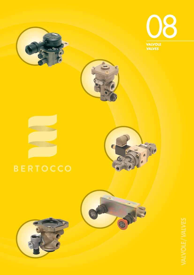
67 VLVOLE/ VLVES VLVOL COMNDO FRENO MOTORE 3-WY VLVE (ENGINE STOP) D113 D L = 46 * * Sporgenza del pulsante dal piano di fissaggio/ Button protrusion from mounting plane Raccordo filettato: M12 x 1,5/ Thread port: M12 x 1,5 IR TRUCK IR TRUCK TECHNOLOGY 08/5 67
 RISE-LOWER VLVE (2 sections) D120 D120")
 D120 D120 0300 Raccordi filettati: M16 x 1,5/ Thread port: M16 x 1,5 08/6 68 IR TRUCK")
68 VLVOLE/ VLVES VLVOL LZ-BBSS (1 sezione) RISE-LOWER VLVE (1 section) D120 D Raccordi filettati: M16 x 1,5/ Thread port: M16 x 1,5 VLVOL LZ-BBSS (2 sezioni) RISE-LOWER VLVE (2 sections) D120 D Raccordi filettati: M16 x 1,5/ Thread port: M16 x 1,5 VLVOL LZ-BBSS (3 sezioni) RISE-LOWER VLVE (3 sections) D120 D Raccordi filettati: M16 x 1,5/ Thread port: M16 x 1,5 08/6 68 IR TRUCK TECHNOLOGY
 Use as NC (normally closed) 11 = scarico/ exhaust 21 =")
 28Vcc D141 0250 with NC (normally closed) solenoid valve 28Vdc E possibile utilizzare una o")
69 VLVOLE/ VLVES DEVITORE COMNDO PNEUMTICO VLVE WITH PNEUMTIC CONTROL D141 D utilizzabile come N o NC/ usable as NO or NC Impiego come N (normalmente aperto) Use as NO (normally open) 11 = alimentazione/ supply 21 = utilizzazione/ delivery 3 = scarico/ exhaust 4 = comando/ control line Impiego come NC (normalmente chiuso) Use as NC (normally closed) 11 = scarico/ exhaust 21 = utilizzazione/ delivery 3 = alimentazione/ supply 4 = comando/ control line Raccordi filettati/thread port: = M16x1,5 4 = M12x1,5 DEVITORE 2 SEZIONI CON COMNDO ELETTROPNEUMTICO DOUBLE ONE-WY VLVE WITH ELECTROPNEUMTIC CONTROL D141 D * con elettrovalvola NC (normalmente chiusa) 28Vcc D with NC (normally closed) solenoid valve 28Vdc E possibile utilizzare una o ambedue le sezioni sia come N (normalmente aperta) che come NC (normamente chiusa) Each section can be used both as NO (normally open) and as NC (normally closed) * Con azionamento manuale sull elettrovalvola/ With manual solenoid valve control Raccordi filettati/thread port: 1-23 = M12x1, = M16x1,5 11 = G1/4 DEVITORE 2 SEZIONI CON COMNDO PNEUMTICO DOUBLE ONE-WY VLVE WITH PNEUMTIC CONTROL D141 D Raccordi filettati/thread port: 1-2 = M12x1, = M16x1,5 11 = G1/4 IR TRUCK IR TRUCK TECHNOLOGY 08/7 69


70 VLVOLE/ VLVES DEVITORE DIFFERENZITO DIFFERENTITED SELECTOR D150 D D con funzione ND / with ND function Raccordi filettati: M16 x 1,5/ Thread port: M16 x 1,5 SERVO DISTRIBUTORE RELE RELY VLVE D160 D doppio comando/ double command relay valve D mono comando/ single command relay valve Raccordi filettati: M22 x 1,5/ Thread port: M22 x 1,5 VLVOL RIPETITRICE RELY VLVE D161 D Raccordi filettati: M22 x 1,5/ Thread port: M22 x 1,5 DISTRIBUTORE DOPPIO COMNDO IDRULICO DOUBLE HYDRULIC CONTROL DISTRIBUTOR D165 D # sezione idraulica Ø 12/ hydraulic section diameter Ø 12 * per impiego con olio minerale/ for mineral oil use # per impiego con liquido freni/ for braking fluid use Raccordi filettati/thread port: 1-2 = M18x1, = M12x1 08/8 70 IR TRUCK TECHNOLOGY


71 VLVOLE/ VLVES RUBINETTO DI SFRENTUR per sfrenatura di servizio RELESE VLVE for service brake release D171 D impugnatura color nero/ black handgrip Raccordi filettati: M16 x 1,5/ Thread port: M16 x 1,5 RUBINETTO DI SFRENTUR per stazionamento RELESE VLVE for parking release D171 D impugnatura color rosso/red handgrip Raccordi filettati: M16 x 1,5/ Thread port: M16 x 1,5 DEVITORE 3-WY VLVE D171 D impugnatura color giallo/ yellow handgrip Raccordi filettati: M16 x 1,5/ Thread port: M16 x 1,5 RUBINETTO DI SFRENTUR DOPPIO per sfrenatura e stazionamento DUL RELSE VLVE for service brake and parking release D171 D Raccordi filettati: M16 x 1,5/ Thread port: M16 x 1,5 IR TRUCK IR TRUCK TECHNOLOGY 08/9 71
 Use as NC (normally closed) 4 2 11 = scarico/ exhaust 11 12 = alimentazione/ supply 2 12 12 2 = utilizzazione/ delivery 11")

72 VLVOLE/ VLVES DEVITORE 3 WY VLVE D171 D con puntale sferico/ with spherical push-rod Impiego come N (normalmente aperto) Use as NO (normally open) 11 = alimentazione/ supply 12 = scarico/ exhaust 2 = utilizzazione/ delivery 4 Impiego come NC (normalmente chiuso) Use as NC (normally closed) = scarico/ exhaust = alimentazione/ supply = utilizzazione/ delivery 11 Possibile utilizzo come N o NC Usable both as NO and as NC Raccordi filettati:m16 x 1,5/ Thread port: M16 x 1,5 SERVOUTODISTRIBUTORE RELY EMERGENCY VLVE D181 D Raccordi filettati/thread port: 4 = M16x1, = M22x1,5 SERVOUTODISTRIBUTORE con rubinetto di sfrenatura RELY EMERGENCY VLVE with release valve D181 D Raccordi filettati/thread port: 4 = M16x1, = M22x1,5 RUBINETTO DI SFRENTUR per servoautodistributore RELESE VLVE for relay emergency valve Z 7063 Da utilizzarsi solo sul servoautodistributore predisposto Only for suitable relay emergency valve Raccordo filettato:m22 x 1,5/ Thread port: M22 x 1,5 08/10 72 IR TRUCK TECHNOLOGY
73 VLVOLE/ VLVES RIDUTTORE PRZILE PRTIL PRESSURE REDUCING VLVE D190 Rapporto di riduzione Ratio D :2 D :2 D :1.8 D :2 D D D D P2 bar P2 bar P2 bar P2 bar P1 bar P1 bar P1 bar P1 bar P1 = pressione di comando/ control pressure P2 = pressione di risposta/ delivery pressure Raccordi filettati: M22 x 1,5/ Thread port: M22 x 1,5 RIDUTTORE PROPORZIONLE PRESSURE REDUCING VLVE D191 Rapporto di riduzione Ratio D :2 D :1.8 D :1.5 D D D P2 bar P2 bar P2 bar P1 bar P1 = pressione di comando/ control pressure P2 = pressione di risposta/ delivery pressure P1 bar P1 bar Raccordi filettati: M22 x 1,5/ Thread port: M22 x 1,5 IR TRUCK IR TRUCK TECHNOLOGY 08/11 73

74 VLVOLE/ VLVES VLVOL DTTTRICE DPTOR VLVE D192 Rapporto di riduzione Ratio D :2 D :2 D :1.8 D :1.5 D D D D P2 bar P2 bar P2 bar P2 bar P1 bar P1 bar P1 bar P1 bar P1 = pressione di comando/ control pressure P2 = pressione di risposta/ delivery pressure Raccordi filettati:m22 x 1,5/ Thread port: M22 x 1,5 08/12 74 IR TRUCK TECHNOLOGY
75
76 NOTE/ NOTES 09/4 76 IR TRUCK TECHNOLOGY
77 ELETTROVLVOLE/ SOLENOID VLVES ELETTROVLVOL NC SOLENOID VLVE NC E286 - E288 E E Tensione di esercizio Operating voltage 28V 12V Raccordi filettati : G 1/8 / Thread port: G1/8 NC = normalmente chiusa/ NC = normally closed ELETTROVLVOL N SOLENOID VLVE NO E286 - E288 E E Tensione di esercizio Operating voltage 28V 12V Raccordi filettati: G 1/8 / Thread port: G1/8 N = normalmente aperta /NO = normally open GRUPPO 2 ELETTROVLVOLE NC - 28V DOUBLE SOLENOID VLVE NC - 28V E286 E E senza connettori/ without connectors Raccordi filettati: G 1/8 / Thread port: G1/8 NC = normalmente chiusa/ NC = normally closed GRUPPO 2 ELETTROVLVOLE NC+N - 28V DOUBLE SOLENOID VLVE NC+NO - 28V E286 E Raccordi filettati: G 1/8 / Thread port: G1/8 N = normalmente aperta /NO = normally open NC = normalmente chiusa/ NC = normally closed IR TRUCK IR TRUCK TECHNOLOGY 09/5 77
78 ELETTROVLVOLE/ SOLENOID VLVES GRUPPO 2 ELETTROVLVOLE N - 28V DOUBLE SOLENOID VLVE NO - 28V E286 E N = normalmente aperta /NO = normally open Raccordi filettati:g 1/8 / Thread port: G1/8 09/6 78 IR TRUCK TECHNOLOGY
 Use as NC (normally closed) 1 = alimentazione/ supply 2 = utilizzazione/ delivery 3 = scarico/ exhaust 4 =")


79 ELETTROVLVOLE/ SOLENOID VLVES DEVITORE COMNDO PNEUMTICO VLVE WITH PNEUMTIC CONTROL E287 E Raccordi filettati: G 1/8 / E Raccordi filettati: G 1/4 / Thread port: G1/8 Thread port: G1/4 Impiego come NC (normalmente chiuso) Use as NC (normally closed) 1 = alimentazione/ supply 2 = utilizzazione/ delivery 3 = scarico/ exhaust 4 = comando/ control line Impiego come N (normalmente aperto) Use as NO (normally open) 1 = scarico/ exhaust 2 = utilizzazione/ delivery 3 = alimentazione/ supply 4 = comando/ control line CENTRLIN LES - Dispositivo elettronico sollevamento assale LES ELECTRONIC UNIT - Electronic device for lifting axle system control E292 E con pressostato di massima/ with high pressure gauge E con pressostato di minima e massima/ with low and high pressure gauges Dispositivi conformi alle normative Europee sulla compatibilità elettromagnetica. Numero di omologazione e Devices that comply with the European electromagnetic compatibility regulations. Homologation N. e La centralina può essere applicata su impianti già esistenti e provvisti di sollevatore, rendendolo conforme alle norme vigenti. The electronic central unit may be installed on existing vehicles already equipped with a lifting axle system, making the existing system comply with the current directive. IR TRUCK IR TRUCK TECHNOLOGY 09/7 79
80 ELETTROVLVOLE/ SOLENOID VLVES GRUPPO 2 ELETTROVLVOLE NC - 28V con protezione sullo scarico e completa di connettore e cavo L = 400 mm DOUBLE SOLENOID VLVE NC - 28V with exhaust protection and with connector and cable L = 400 mm Z Z 1050 Z 1051 senza connettore/without connector con terminale maschio superseal/ with superseal male connector Z 1054 completo di terminali maschio e femmina superseal with superseal male and female connectors Raccordi filettati: G1/8 / Thread ports: G1/8 ELETTROVLVOL CON DEVITORE 5 VIE - 24V 5-WY SOLENOID VLVE - 24V Z Z 2005 Raccordi filettati: G1/4 / Thread ports: G1/4 ELETTROVLVOL CON DEVITORE 3 VIE - 24V 3-WYSOLENOID VLVE - 24V Z Z 2008 normalmente aperta/ normally open Z 2009 normalmente chiusa/ normally closed Raccordi filettati: G1/8 / Thread ports: G1/8 09/8 80 IR TRUCK TECHNOLOGY
81 ELETTROVLVOLE/ SOLENOID VLVES ELETTROVLVOL CON DEVITORE 3 VIE - 24V 3-WY SOLENOID VLVE - 24V Z Z 2010 normalmente aperta/normally open Z 2011 normalmente chiusa/normally closed Raccordi filettati: G1/4 / Thread ports: G1/4 DEVITORE COMNDO PNEUMTICO 5 VIE 5-WY VLVE WITH PNEUMTIC CONTROL Z Z 6208 Raccordi filettati: G1/4 / Thread ports: G1/4 DEVITORE CON COMNDO LEV 3 VIE 3-WY VLVE WITH LEVER CONTROL Z Z 6209 Raccordi filettati: G1/4 / Thread ports: G1/4 IR TRUCK IR TRUCK TECHNOLOGY 09/9 81
82 NOTE/ NOTES 09/4 82 IR TRUCK TECHNOLOGY
83
84 NOTE/ NOTES 10/4 84 IR TRUCK TECHNOLOGY
 per rimorchio PLM")
 per motrice PLM COUPLING (CUN type) for truck G205 G205 0000 con interruttore/ with switch G205 0040 G205 0050 con leva a sinistra/")
85 GIUNTI DI CCOPPIMENTO/ PLM COUPLINGS GIUNTI DI CCOPPIMENTO (tipo CUN) per trattore di semirimorchio PLM COUPLING (CUN type) for semitrailer tractor G203 G * G completo di bocchettone per tubo in gomma/ with fitting for rubber hose * Raccordi filettati:m16x1,5/ Thread port: M16x1,5 bbinabile con G206/ In combination with G206 GIUNTO DI CCOPPIMENTO (tipo CUN) per rimorchio PLM COUPLING (CUN type) for trailer G204 G * G completo di bocchettone per tubo in gomma/ with fitting for rubber hose * Raccordi filettati:m16x1,5/ Thread port: M16x1,5 bbinabile con G205/ In combination with G205 GIUNTO DI CCOPPIMENTO (tipo CUN) per motrice PLM COUPLING (CUN type) for truck G205 G con interruttore/ with switch G G con leva a sinistra/ with left lever G con interruttore e raccordi M22x1,5/ with switch and fittings M22x1,5 G con raccordi M22x1,5/ with fittings M22x1,5 Raccordi filettati:m18x1,5/ Thread port: M18x1,5 bbinabile con G204/ In combination with G204 GIUNTO DI CCOPPIMENTO (tipo CUN) per semirimorchio PLM COUPLING (CUN type) for semitrailer G206 G G con raccordi M22x1,5/ with fittings M22x1,5 Raccordi filettati:m18x1,5/ Thread port: M18x1,5 bbinabile con G203/ In combination with G203 IR TRUCK IR TRUCK TECHNOLOGY 10/5 85
 PLM COUPLING - red colour (supply line) G550 G550 0000 per veicoli a motore/ for trucks G550 0010 per veicoli rimorchiati/ for trailers pparecchi conformi alle norme/ In accordance with UNI 9129 -")
86 GIUNTI DI CCOPPIMENTO/ PLM COUPLINGS GIUNTO DI CCOPPIMENTO - colore rosso (automatico/aliment.) PLM COUPLING - red colour (supply line) G550 G per veicoli a motore/ for trucks G per veicoli rimorchiati/ for trailers pparecchi conformi alle norme/ In accordance with UNI ISO1728 directives Raccordi filettati:m16x1,5/ Thread port: M16x1,5 GIUNTO DI CCOPPIMENTO - colore giallo (moderabile/comando) PLM COUPLING - yellow colour (control line) G550 G G G per veicoli a motore/ for trucks per veicoli rimorchiati/ for trailers per veicoli rimorchiati, completo di presa di controllo pressione for trailers, with test connector pparecchi conformi alle norme/ In accordance with UNI ISO1728 directives Raccordi filettati:m16x1,5/ Thread port: M16x1,5 GIUNTO DI CCOPPIMENTO CON FILTRO - colore rosso (automatico/alimentazione) PLM COUPLING WITH FILTER - red colour (supply line) G551 G per veicoli rimorchiati/ for trailers pparecchi conformi alle norme/ In accordance with UNI ISO1728 directives Raccordo filettato:m16x1,5/ Thread port: M16x1,5 GIUNTO DI CCOPPIMENTO CON FILTRO - colore giallo (moderabile/comando) PLM COUPLING WITH FILTER - yellow colour (control line) G per veicoli rimorchiati/ for trailers G per veicoli rimorchiati, completo di presa di controllo pressione for trailers, with test connector pparecchi conformi alle norme/ In accordance with UNI ISO1728 directives Raccordi filettati:m16x1,5/ Thread port: M16x1,5 10/6 86 IR TRUCK TECHNOLOGY


87 GIUNTI DI CCOPPIMENTO/ PLM COUPLINGS IMPUGNTUR PER GIUNTI DI CCOPPIMENTO TIPO ISO GRIPS FOR PLM COUPLING ISO TYPE G555 G kit per agevolare l accoppiamento ed il disaccoppiamento dei giunti mobili tipo ISO kit to simplify connection and disconnection of ISO coupling joints Si realizzano confezioni personalizzate Customized kits are made on request SUPPORTO GIUNTI DI CCOPPIMENTO SUPPORT FORM PLM COUPLING Utilizzabile per giunti tipo ISO/ Suitable for ISO type palm couplings KIT INTERMEDIO PER GIUNTI ISO DPTOR COUPLING KIT SB GIUNTI ISO CON VLVOL/ ISO TYPE PLM COUPLINGS WITH VLVE Idoneo per semigiunti Cuna e rimorchio con giunti ISO Suitable for: truck with Cuna couplings and trailer with ISO couplings KIT INTERMEDIO PER GIUNTI ISO DPTOR COUPLING KIT SB GIUNTI CUN CON VLVOL/ CUN TYPE PLM COUPLINGS WITH VLVE Idoneo per trattore con giunti ISO E semirimorchio con semigiunti Cuna Suitable for: truck with ISO couplings and trailer with Cuna couplings IR TRUCK IR TRUCK TECHNOLOGY 10/7 87
88 NOTE/ NOTES 10/4 88 IR TRUCK TECHNOLOGY
89
90 NOTE/ NOTES 11/4 90 IR TRUCK TECHNOLOGY
 MODULTING VLVE (with fittings) M209 M209 1000 taratura/setting pressure 7.")

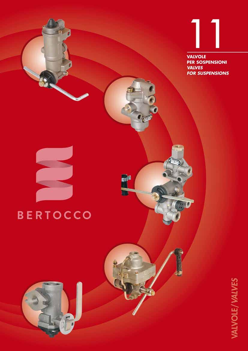
91 VLVOLE PER SOSPENSIONI/ VLVES FOR SUSPENSIONS MODULTORE DI PRESSIONE MODULTING VLVE M209 M taratura/setting pressure 7.5 bar M taratura/setting pressure 4.5 bar Raccordi filettati: M14 x 1,5/ Thread ports: M14 x 1,5 MODULTORE DI PRESSIONE (completo di raccordi) MODULTING VLVE (with fittings) M209 M taratura/setting pressure 7.5 bar Raccordi: M12 x 1 con attacco per tubo sbordato Thread fittings: M12 x 1 with attachment for flared pipe MODULTORE DI PRESSIONE con comando scarico MODULTING VLVE with exhaust control M218 M taratura/setting pressure 7.5 bar Raccordi filettati: M14 x 1,5/ Thread ports: M14 x 1,5 MODULTORE DI PRESSIONE con comando scarico (completo di raccordi ad ogiva) MODULTING VLVE with exhaust control (with nose fittings) M218 M taratura/setting pressure 7.5 bar Raccordi: 1 e 2 T10-4 T6/ Fittings: 1 and 2 T10-4 T6 IR TRUCK IR TRUCK TECHNOLOGY 11/5 91
92 VLVOLE PER SOSPENSIONI/ VLVES FOR SUSPENSIONS MODULTORE DI PRESSIONE MODULTING VLVE M221 angolo di lavoro 56 / working range 56 M taratura/setting pressure 6 bar M taratura/setting pressure 7.5 bar M taratura/setting pressure 4 bar M M M Pressione di risposta (bar) Delivery pressure (bar) Pressione di risposta (bar) Delivery pressure (bar) Pressione di risposta (bar) Delivery pressure (bar) Rotazione leva (gradi)/ Lever rotation (degree) Rotazione leva (gradi)/ Lever rotation (degree) Rotazione leva (gradi)/ Lever rotation (degree) Raccordi filettati: M14 x 1,5/ Thread ports: M14 x 1,5 MODULTORE DI PRESSIONE MODULTING VLVE M221 angolo di lavoro 68 / working range 68 M taratura/setting pressure 6 bar M taratura/setting pressure 8 bar M M Pressione di risposta (bar) Delivery pressure (bar) Pressione di risposta (bar) Delivery pressure (bar) Rotazione leva (gradi)/ Lever rotation (degree) Rotazione leva (gradi)/ Lever rotation (degree) Raccordi filettati: M14 x 1,5/ Thread ports: M14 x 1,5 11/6 92 IR TRUCK TECHNOLOGY
93 VLVOLE PER SOSPENSIONI/ VLVES FOR SUSPENSIONS MODULTORE DI PRESSIONE MODULTING VLVE M229 angolo di lavoro 24 / working range 24 M taratura/setting pressure 7.5 bar M taratura/setting pressure 4.5 bar M taratura/setting pressure 1.8 bar M M M Pressione di risposta (bar) Delivery pressure (bar) Pressione di risposta (bar) Delivery pressure (bar) Pressione di risposta (bar) Delivery pressure (bar) Rotazione leva (gradi)/ Lever rotation (degree) Rotazione leva (gradi)/ Lever rotation (degree) Rotazione leva (gradi)/ Lever rotation (degree) Raccordi filettati: 1 e 2 = M14 x 1,5/ Thread ports: 1 and 2 = M14 x 1,5 4 = con filtro 4 = with filter MODULTORE DI PRESSIONE - con comando scarico MODULTING VLVE - with exhaust control M229 angolo di lavoro 24 / working range 24 M taratura/setting pressure 7.5 bar M taratura/setting pressure 4.5 bar M taratura/setting pressure 7.5 bar senza asta/ without lever M M M Pressione di risposta (bar) Delivery pressure (bar) Pressione di risposta (bar) Delivery pressure (bar) Pressione di risposta (bar) Delivery pressure (bar) Rotazione leva (gradi)/ Lever rotation (degree) Rotazione leva (gradi)/ Lever rotation (degree) Rotazione leva (gradi)/ Lever rotation (degree) Raccordi filettati: 1 e 2 = M14 x 1,5/ Thread ports: 1 and 2 = M14 x 1,5 4 = G1/8 4 = G1/8 IR TRUCK IR TRUCK TECHNOLOGY 11/7 93
94 VLVOLE PER SOSPENSIONI/ VLVES FOR SUSPENSIONS MODULTORE DI PRESSIONE - con comando scarico (completo di raccordi ad ogiva) MODULTING VLVE - with exhaust control (with nose fittings) M229 angolo di lavoro 24 / working range 24 M taratura/setting pressure 7.5 bar CRTTERISTIC COME M SME DIGRM S M Raccordi: 1 e 2 T10-4 T6/ Fittings: 1 and 2 for T10-4 T6 MODULTORE DI PRESSIONE - con comando scarico (completo di raccordi ad ogiva) MODULTING VLVE - with exhaust control (with nose fittings) M229 angolo di lavoro 24 / working range 24 M taratura/setting pressure 4.5 bar CRTTERISTIC COME M SME DIGRM S M Raccordi: 1 e 2 T10-4 T6/ Fittings: 1 and 2 T10-4 T6 MODULTORE DI PRESSIONE - con comando scarico MODULTING VLVE - with exhaust control M229 angolo di lavoro 34 / working range 34 M taratura/setting pressure 7.5 bar M Raccordi filettati: 1 e 2 = M14 x 1,5-4 = G1/8 Thread ports: 1 and 2 = M14 x 1,5-4 = G1/8 Pressione di risposta (bar) Delivery pressure (bar) Rotazione leva (gradi)/ Lever rotation (degree) 11/8 94 IR TRUCK TECHNOLOGY

95 VLVOLE PER SOSPENSIONI/ VLVES FOR SUSPENSIONS MODULTORE DI PRESSIONE - con comando scarico MODULTING VLVE - with exhaust control M229 angolo di lavoro 34 / working range 34 M taratura/setting pressure 7.5 bar CRTTERISTIC COME M SME DIGRM S M Raccordi filettati: 1 e 2 = M14 x 1,5/ Thread ports: 1 and 2 = M14 x 1,5 4 = G1/8 4 = G1/8 MODULTORE DI PRESSIONE - con comando scarico MODULTING VLVE - with exhaust control M229 angolo di lavoro 34 / working range 34 M taratura/setting pressure 7.5 bar CRTTERISTIC COME M SME DIGRM S M Raccordi filettati: 1 e 2 = M14 x 1,5/ Thread ports: 1 and 2 = M14 x 1,5 4 = G1/8 4 = G1/8 IR TRUCK IR TRUCK TECHNOLOGY 11/9 95

96 VLVOLE PER SOSPENSIONI/ VLVES FOR SUSPENSIONS MODULTORE COMNDO PNEUMTICO PNEUMTIC CONTROL VRIBLE VLVE M230 M M M M M M M M M M P2 bar P2 bar P2 bar P2 bar P2 bar P4 bar P4 bar P4 bar P4 bar P4 bar P4 = pressione di comando/ control pressure P2 = pressione di risposta/ delivery pressure Raccordi filettati:m14 x 1,5/ Thread port: M14 x 1,5 MODULTORE COMNDO PNEUMTICO (completo di raccordi a ogiva) PNEUMTIC CONTROL VRIBLE VLVE (with nose fittings) M230 M Raccordi: 1 e 2 T6/ Fittings: 1 and 2 T6 4 TT8 (3 vie) 4 TT8 (3 way) 11/10 96 IR TRUCK TECHNOLOGY
97 VLVOLE PER SOSPENSIONI/ VLVES FOR SUSPENSIONS MODULTORE COMNDO PNEUMTICO PNEUMTIC CONTROL VRIBLE VLVE M231 Rapporto di riduzione Ratio M :1.65 M :2 M :1.625 M :2.77 M :1 potenz. M :1.33 M :1.05 M M M M P2 bar P2 bar P2 bar P2 bar P4 bar P4 bar P4 bar P4 bar M M M P2 bar P2 bar P2 bar P4 bar P2 = pressione di risposta/ delivery pressure P4 = pressione di comando/ control pressure P4 bar P4 bar Raccordi filettati: M22 x 1,5/ Thread port: M22 x 1,5 IR TRUCK IR TRUCK TECHNOLOGY 11/11 97


98 VLVOLE PER SOSPENSIONI/ VLVES FOR SUSPENSIONS VLVOL LIVELLTRICE LEVELLING VLVE M236 M con passaggio nominale/ with nominal diameter = Ø 1,3 M con passaggio nominale/ with nominal diameter = min. Ø 1,3 - max Ø 3 Raccordi filettati: M12 x 1,5/ Thread ports: M12 x 1,5 VLVOL LIVELLTRICE (con variazione del punto neutro) LEVELLING VLVE (with modification of neutral position) M236 M con passaggio nominale/ with nominal diameter = Ø 1,3 angolo di variazione del punto neutro/ neutral position modification = 16 Raccordi filettati: M12 x 1,5/ Thread ports: M12 x 1,5 VLVOL LIVELLTRICE (con fine corsa pneumatico) LEVELLING VLVE (with pneumatic stopping stroke) M236 M con passaggio nominale/ with nominal diameter = min. Ø 1,3 - max Ø 3 valvola con fine corsa regolato a 30 / valve with stopping stroke adjust at 30 campo di regolazione del fine corsa = min 25 - max 55 adjusting range of stopping stroke = min 25 - max 55 Raccordi filettati: 1 e 2 = M12 x 1,5 Thread ports: 1 and 2 = M12 x 1,5 12 e 22 = M16 x 1,5 12 and 22 = M16 x 1,5 VLVOL LIVELLTRICE (con fine corsa e variazione del punto neutro) LEVELLING VLVE (with stopping stroke and modification neutral position) M236 M con passaggio nominale/ with nominal diameter = min. Ø 1,3 - max Ø 3 valvola con fine corsa regolato a 30 / valve with stopping stroke adjust at 30 campo di regolazione del fine corsa = min 25 - max 55 adjusting range of stopping stroke = min 25 - max 55 angolo di variazione del punto neutro/ neutral position modification = 16 Raccordi filettati: 1,2 e 4 = M12 x 1,5 Thread ports: 1,2 and 4 = M12 x 1,5 12 e 22 = M16 x 1,5 12 and 22 = M16 x 1,5 11/12 98 IR TRUCK TECHNOLOGY

99 VLVOLE PER SOSPENSIONI/ VLVES FOR SUSPENSIONS VLVOL LIVELLTRICE PER UTOBUS LEVELLING VLVE FOR BUS M236 M Raccordi filettati: M10 x 1/ Thread ports: M10 x 1 IR TRUCK IR TRUCK TECHNOLOGY 11/13 99
 outlet pressure (bar) P4 bar P2 pressione")
 lever rotation (degree) pressione di alimentazione (bar) supply pressure (bar) Raccordi filettati: M22 x 1,5/ Thread ports: M22 x 1,5 CORRETTORE MNULE EMPTY LOD VLVE M269")
 outlet pressure (bar) C P2=P1 B 4.1 bar 2.")
100 VLVOLE PER SOSPENSIONI/ VLVES FOR SUSPENSIONS CORRETTORE MECCNICO LOD SENSING VLVE M268 M Posizione leva-condizione veicolo/ Position lever-vehicle condition 1 = Extra corsa Extra stroke B = Mezzo carico Semi laden position C = Vuoto Empty = Pieno carico Fully laden position C1 = Extra corsa Extra stroke P2 P1 = 7 bar pressione di risposta (bar) outlet pressure (bar) P4 bar P2 pressione di risposta (bar) outlet pressure (bar) 1.1 leva in pos. e leva in pos. B 3.1 leva in pos. C max 4 1 leva in pos. C1 P1 rotazione leva (gradi) lever rotation (degree) pressione di alimentazione (bar) supply pressure (bar) Raccordi filettati: M22 x 1,5/ Thread ports: M22 x 1,5 CORRETTORE MNULE EMPTY LOD VLVE M269 M Posizione leva Level Position Condizione di carico del veicolo Vehicle load condition a vuoto empty vehicle B veicolo a mezzo carico half laden vehicle Limitazione della pressione di risposta Limiting delivery pressure P2 max = 2.1 P2 max = ,3 0-0,3 P2 = pressione di risposta (bar) outlet pressure (bar) C P2=P1 B 4.1 bar 2.1 bar C veicolo a pieno carico full laden vehicle P2 max = 2.1 P1 = pressione di alimentazione (bar) supply pressure (bar) Raccordi filettati: M22 x 1,5/ Thread ports: M22 x 1, /14 IR TRUCK TECHNOLOGY

101
102 NOTE/ NOTES /4 IR TRUCK TECHNOLOGY


103 VLVOLE DI REGOLZIONE/ DJUSTING VLVES VLVOL DI SCRICO RPIDO QUICK RELESE VLVE V107 V Raccordi filettati: M22x1,5/ Thread port: M22x1,5 VLVOL DI SCRICO RPIDO QUICK RELESE VLVE V107 V Raccordi filettati: G1/4 / Thread port: G1/4 DOPPI VLVOL DI RRESTO DOUBLE CHECK VLVE V110 V passaggio nominale/ nominal diameter Ø = entrata/inlet 12 = entrata/inlet 2 = uscita/ outlet Raccordi filettati: M22x1,5/ Thread port: M22x1,5 DOPPI VLVOL DI RRESTO DOUBLE CHECK VLVE V110 V * passaggio nominale/ nominal diameter Ø 4 V ** passaggio nominale/ nominal diameter Ø 8 * Raccordi filettati: G1/8 / Thread port: G1/8 ** Raccordi filettati: G1/4 / Thread port: G1/4 IR TRUCK IR TRUCK TECHNOLOGY 12/5 103
104 VLVOLE DI REGOLZIONE/ DJUSTING VLVES PRESE DI CONTROLLO MSCHIO MLE TEST CONNECTOR V108 Filettatura Thread V M16 x 1,5 V M22 x 1,5 V G1/4 V M14 x 1,5 ttacco conforme alla norma UNI ISO 3583 Connector according to UNI ISO 3583 PRESE DI CONTROLLO FEMMIN FEMLE TEST CONNECTOR V108 Filettatura Thread V M12 x 1,5 V M14 x 1,5 V M16 x 1,5 V M18 x 1,5 V M22 x 1,5 ttacco conforme alla norma UNI ISO 3583 Connector according to UNI ISO 3583 Rondelle di tenuta per prese di controllo femmina Washer for female test connector Dim. rondella/washer dim. lluminio/luminium Rame/Copper Ø est. x Ø int. Filettatura/Thread RON 0093 RON x 4 M12 x 1,5 RON 0098 RON x 6 M14 x 1,5 RON 0095 RON x 8 M16 x 1,5 RON 0096 RON x 8 M18 x 1,5 RON 0094 RON x 12 M22 x 1, /6 IR TRUCK TECHNOLOGY


105 VLVOLE DI REGOLZIONE/ DJUSTING VLVES TTCCHI PER PRESE DI CONTROLLO - terminale per tubo in gomma FITTINGS FOR TEST CONNECTORS - fitting for rubber hose V108 V diametro interno Ø 8/int. diameter Ø 8 V diametro interno Ø 6/int. diameter Ø 6 TTCCHI PER PRESE DI CONTROLLO - terminale per tubo in rilsan FITTINGS FOR TEST CONNECTORS - fitting for rilsan pipe V108 V diametro esterno Ø 6/ext. diameter Ø 6 V * V diametro esterno Ø 8/ext. diameter Ø 8 * Terminale raccordo femmina G1/4 / Female connection thread G1/4 TTCCO PER PRES DI CONTROLLO - terminale per tubo in Rilsan FITTING FOR TEST CONNECTOR - fitting for Rilsan pipe Z Z 0113 raccordo a gomito per tubo diametro esterno Ø 8 elbow fitting for pipe ext. diameter Ø 8 IR TRUCK IR TRUCK TECHNOLOGY 12/7 105

106 VLVOLE DI REGOLZIONE/ DJUSTING VLVES LIMITTORE DI PRESSIONE PRESSURE LIMITING VLVE V208 Valore di taratura Press. di aliment. Campo di regolazione Setting pressure Supply pressure djusting range V da/ from0.5 a/ to 2 V da/ from0.5 a/ to 2 V da/ from 2 a/ to 6 V da/ from 2 a/ to 6 V da/ from 2 a/ to 6 V da/ from 2 a/ to 6 V ± da/ from 2 a/ to 6 V da/ from 2 a/ to 6 V ± da/ from 6 a/ to 9 V da/ from 6 a/ to 9 V ± da/ from 6 a/ to 9 V ± da/ from 6 a/ to 9 V ± da/ from 6 a/ to 9 Raccordi filettati: M16x1,5/ Thread port: M16x1,5 VLVOL DI RITENUT CHECK VLVE V604 V V con by-pass Ø 1/ with by-pass Ø 1 Montare la valvola con la freccia rivolta nel senso dell alimentazione Install the valve with the arrow pointing towards air supply direction Passaggio nominale/nominal diameter Ø 6,5 Raccordi filettati: G1/4 / Thread port: G1/4 VLVOL DI RITENUT CHECK VLVE V604 V Montare la valvola con la freccia rivolta nel senso dell alimentazione Install the valve with the arrow pointing towards air supply direction Passaggio nominale/nominal diameter Ø 9 Raccordi filettati: M22x1,5/ Thread port: M22x1, /8 IR TRUCK TECHNOLOGY
/ Setting pressure (bar) Con valvola di riten. sez. 21 With check valve on sect. 21 V608 0000 6.2-0.3 6.2-0.3 V608 0100 V608 0001 4.2-0.3 4.")


107 VLVOLE DI REGOLZIONE/ DJUSTING VLVES VLVOL PRESSIONE CONTROLLT DOPPI DOUBLE CIRCUIT PROTECTION VLVE V608 Sezione/Section 21 Sezione/Section 22 Val. di taratura (bar)/ Setting pressure (bar) Con valvola di riten. sez. 21 With check valve on sect. 21 V V V V V V V V V V V V V V Con valvola di ritenuta With check valve Raccordi filettati/thread port: = M22x1,5 22 = M16x1,5 VLVOL PRESSIONE CONTROLLT (con ritorno limitato) CHRGING VLVE (with limited return flow) V609 Valore di taratura (bar) Setting pressure (bar) V V V V V V V V V V V V V V V V V V V Con ritorno limitato With limited return 1 2 Raccordi filettati: M22x1,5/ Thread port: M22x1,5 IR TRUCK IR TRUCK TECHNOLOGY 12/9 107
 Senza ritorno Without return 1 2 V609 0105 0.5-0.3 V609 0108 0.8-0.3 V609 0110 1.0-0.3 V609 0136 3.6-0.3 V609 0140 4.0-0.3 V609 0142 4.2-0.3 V609 0145 4.5-0.3 V609 0150 5.0-0.3 V609 0152 5.")

108 VLVOLE DI REGOLZIONE/ DJUSTING VLVES VLVOL PRESSIONE CONTROLLT (senza ritorno) CHRGING VLVE (without return flow) V609 (con valvola di ritenuta/ with check valve on) Valore di taratura (bar) Setting pressure (bar) Senza ritorno Without return 1 2 V V V V V V V V V V V V V V V V V V V Raccordi filettati: M22x1,5/ Thread port: M22x1,5 VLVOL PRESSIONE CONTROLLT (con ritorno totale) CHRGING VLVE (with total return flow) V609 Valore di taratura (bar) Setting pressure (bar) Con ritorno totale With total return 1 2 V V V V V V V V V V V V V V V V V V V Raccordi filettati: M22x1,5/ Thread port: M22x1, /10 IR TRUCK TECHNOLOGY
 Setting pressure (bar) V609 1005 con ritorno limitato/with limited return flow 0.5 V609 1560 con ritorno totale/with total return flow 6.")


109 VLVOLE DI REGOLZIONE/ DJUSTING VLVES VLVOL PRESSIONE CONTROLLT (con staffa ruotata) CHRGING VLVE (with rotated braket) V609 Valore di taratura (bar) Setting pressure (bar) V con ritorno limitato/with limited return flow 0.5 V con ritorno totale/with total return flow 6.0 Raccordi filettati: M22x1,5/ Thread port: M22x1,5 FILTRO DI LINE IR LINE FILTER V610 V Utilizzo per sospensioni/for suspension: 1-2 entrata/inlet uscita/ outlet Utilizzo per frenatura/for air brake: 2-1 entrata/inlet uscita/ outlet Raccordi filettati: M22x1,5/ Thread port: M22x1,5 SELETTORE DI CIRCUITO (funzione ND ) CIRCUIT SELECTOR ( ND function) V612 V passaggio nominale/ nominal diameter Ø = entrata/ inlet 12 = entrata/ inlet 2 = uscita/ outlet Raccordi filettati: M22x1,5/ Thread port: M22x1,5 IR TRUCK IR TRUCK TECHNOLOGY 12/11 109

110 VLVOLE DI REGOLZIONE/ DJUSTING VLVES ESSICCTORE D RI IR DRYER V615 Regolatore di pressione Pressure regulator Riscaldatore Heater CUT-OUT ON - OFF Potenza pressure difference V cc Power V V W V W Riscaldatore con attacco a baionetta/ Bayonet heater fastener Raccordi filettati 22 e 4-23: M12x1,5/ Thread port 22 and 4-23: M12x1,5 Raccordi filettati 1 e 21: M22x1,5/ Thread port 1 and 21: M22x1,5 VLVOL PROTEZIONE SCRICO (per scarico filettati) EXHUST PROTECTION VLVE (for thread exhaust ports) V650 V V V V Filettatura Thread G1/8 G1/4 M12x1,5 M16x1,5 La protezione scarico non è da utilizzarsi sulle valvole installate con lo scarico rivolto verso l'alto. Don't use the exhaust protection on valves fitted with exhaust facing upwards /12 IR TRUCK TECHNOLOGY


111 VLVOLE DI REGOLZIONE/ DJUSTING VLVES VLVOL DI SICUREZZ SFETY VLVE V660 Taratura Setting Filettatura Thread port V bar M16 x 1, 5 V bar M16 x 1, 5 V bar M16 x 1, 5 VLVOL DI SICUREZZ SFETY VLVE V660 Taratura Setting Filettatura Thread port V bar M20 x 1, 5 V bar M20 x 1, 5 V bar M20 x 1, 5 VLVOL SCRICO CONDENS MNULE MNUL DRIN VLVE V680 Filettatura Thread port V M22 x 1,5 VLVOL SCRICO CONDENS UTOMTIC UTOMTIC DRIN VLVE V681 Filettatura Thread port V M22 x 1,5 Pressione minima di esercizio/ Min. operating pressure : apertura/ opening 0.5 bar chiusura/ closure 1.5 bar IR TRUCK IR TRUCK TECHNOLOGY 12/13 111
112 NOTE/ NOTES /4 IR TRUCK TECHNOLOGY
113
114 NOTE/ NOTES /4 IR TRUCK TECHNOLOGY
 Setting pressure-bar - Pmax (H) B3500 3,5 B3501 2,5 B3502 3,0 B3503 4,0 B3504 4,5 B3505 5,0 B3506 2,0 B3507 2,7 B3508 3,8 Dispositivo")
115 DISPOSITIVI/ DEVICES LES - XLE LIFT ELECTRONIC SYSTEM Dispositivo di sollevamento asse con controllo del carico LES - XLE LIFT ELECTRONIC SYSTEM Lifting device with load control con 1 pressostato/ with one pressure switch Valore di regolazione-bar - Pmax (H) Setting pressure-bar - Pmax (H) B3500 3,5 B3501 2,5 B3502 3,0 B3503 4,0 B3504 4,5 B3505 5,0 B3506 2,0 B3507 2,7 B3508 3,8 Dispositivo conforme alle normative Europee sulla compatibilità elettromagnetica. Device comply with the European electromagnetic compatibility regulation. Numero di omologazione/ Homologation N : LES - XLE LIFT ELECTRONIC SYSTEM Dispositivo di sollevamento asse con controllo del carico LES - XLE LIFT ELECTRONIC SYSTEM Lifting device with load control con 2 pressostati/ with two pressure switches Valore di regolazione/ Setting pressure - bar Pmax (H) Pmin (L) B3600 3,5 2,0 B3601 2,5 1,0 B3602 3,0 1,5 B3603 4,0 2,2 B3604 4,5 2,5 B3605 5,0 3,0 B3606 2,0 1,0 B3607 4,5 2,0 B3608 2,5 1,2 B3609 4,0 1,7 Dispositivo conforme alle normative Europee sulla compatibilità elettromagnetica. Device comply with the European electromagnetic compatibility regulation. Numero di omologazione/ Homologation N : IR TRUCK IR TRUCK TECHNOLOGY 13/5 115

116 DISPOSITIVI/ DEVICES LES COMPONENTI - Centralina elettronica LES COMPONENTS - Electronic unit E292 E con pressostato di massima/ with hight pressure E con pressostato di minima e massima/ with low and hight pressure Dispositivi conformi alle normative Europee sulla compatibilità elettromagnetica. Numero di omologazione e Devices that comply with the European electromagnetic compatibility regulations. Homologation N. e La centralina può essere applicata su impianti già esistenti e provvisti di sollevatore, rendendolo conforme alle norme vigenti. The electronic central unit may be installed on existing vehicles already equipped with a lifting axle system, making the existing system comply with the current directive. LES - COMPONENTI Deviatore a 2 sezioni con comando elettropneumatico LES - COMPONENTS Double one-way valve with electropneumatic control D E possibile utilizzare una o ambedue le sezioni sia come N (normalmente aperta) che come NC (normamente chiusa) Each section can be used both as NO (normally open) and as NC (normally closed) Raccordi filettati/thread port: 1-23 = M12x1, = M16x1,5 11 = G1/4 LES - COMPONENTI - Pressostato regolabile LES - COMPONENTS - djustable pressure switch Z 0353 NC - regolabile/ adjustable 1-10 bar NC = normalmente chiusa NC = normally closed Sul corpo è stampigliato il valore di regolazione della pressione, preceduto dalla lettera H o L che sul dispositivo LES ne individua la funzione: H = Pmax Pressostato di massima L = Pmin Pressostato di minima The setting value is marked on the pressure switch body. The H or L letter before the setting value indicates the pressure switch function: H = Pmax Pressure switch L = Pmin Pressure switch Filettatura/Thread: G1/4 LES - COMPONENTI - Targhetta sollevatore LES - COMPONENTS - luminium plate pposita targhetta in alluminio, da fissare sul veicolo, dove deve essere riportato stampigliato il valore di regolazione. lluminium plate to be fixed on the vehicle. The setting value must be printed on the alluminium plate /6 IR TRUCK TECHNOLOGY
117
118 NOTE/ NOTES /4 IR TRUCK TECHNOLOGY
 e la situazione di carico del veicolo rimorchiato.")

119 TTREZZTURE/ EQUIPMENTS SIMULTORE PER PROVE STTICHE (rilievo tempi di intervento su veicoli rimorchiati) TRUCK SIMULTOR FOR STTIC HOMOLOGTION TESTS FB0001 L'attrezzatura FB 0001 permette di simulare il veicolo motore (alimentazione pneumatica del veicolo rimorchiato e comando della frenatura) e la situazione di carico del veicolo rimorchiato. In abbinamento con l'attrezzatura Bertocco per la registrazione delle prove statiche ( ) o con un registratore di pressioni, esso permette l'esecuzione delle prove statiche di omologazione per rimorchi industriali e agricoli previste dalle normative vigenti. The FB 0001 system simulates pneumatically the truck (automatic line and command line for the trailer) and the load condition of the trailer. Used together with the static homologation tests equipment ( ) or a pressure recorder, allows to carry out the static homologation tests defined in the current European regulations for road and agricultural vehicles. SIMULTORE PER PROVE DINMICHE (rilievo decelerazioni su veicoli rimorchiati) TRUCK SIMULTOR FOR DYNMIC HOMOLOGTION TESTS FB0020 L'attrezzatura FB 0020 permette di simulare il veicolo motore (alimentazione pneumatica del veicolo rimorchiato e comando della frenatura) e la situazione di carico del veicolo rimorchiato. In abbinamento con l'attrezzatura Bertocco per la registrazione delle decelerazioni ( ) o con un dispositivo analogo, esso permette l'esecuzione delle prove dinamiche di omologazione per rimorchi industriali e agricoli previste dalle normative vigenti. The FB 0020 system simulates pneumatically the truck (automatic line and command line for the trailer) and the load condition of the trailer. Used together with the deceleration recording equipment ( ) or a similar device, allows to carry out the dynamic homologation tests defined in the current European regulations for road and agricultural vehicles. TTREZZTUR PER REGISTRZIONE DECELERZIONE DECELERTION RECORDING EQUIPMENT L'attrezzatura permette di effettuare rilevi e registrazioni della decelerazione di un veicolo su strada, risultando di ausilio all'esecuzione delle prove dinamiche per l'omologazione di rimorchi industriali e agricoli previste dalle normative vigenti. L'attrezzatura, corredata del relativo software di gestione, è da utilizzarsi attraverso un PC portatile (non fornito). Il prodotto può essere utilizzato in abbinamento al simulatore Bertocco per prove dinamiche FB 0020 o a un simulatore di motrice equivalente. bbinato a FB0001 The system allows to measure and record a vehicle deceleration during road tests, helping in carry out the dynamic homologation tests defined in the current European regulations for road and agricultural vehicles. The system, together with its own software, must be used by means of a laptop PC (not supplied). The system may be used together with the truck simulator for dynamic homologation tests (FB 0020) or an equivalent truck pneumatic simulator. IR TRUCK IR TRUCK TECHNOLOGY 14/5 119


120 TTREZZTURE/ EQUIPMENTS TTREZZTUR PER REGISTRZIONE PROVE STTICHE STTIC HOMOLOGTION TESTS EQUIPMENT L'attrezzatura permette di effettuare rilevi e registrazioni dei risultati di tutte le prove statiche previste dalle normative vigenti per l'omologazione di rimorchi industriali e agricoli. L'attrezzatura, corredata del relativo software di gestione, è da utilizzarsi attraverso un PC portatile (non fornito). Il prodotto può essere utilizzato in abbinamento al simulatore Bertocco per prove statiche FB 0001 o a un simulatore di motrice equivalente. The system allows to evaluate and record the results of the static homologation tests defined in the current European regulations for road and agricultural vehicles. The system, together with its own software, must be used by means of a laptop PC (not supplied). The system may be used together with the truck simulator for static homologation tests (FB 0001) or an equivalent truck pneumatic simulator. PEDLE DI COMNDO PEDL (per rilievo tempi di intervento su veicoli a motore) Pedale di comando, da collegarsi all'attrezzatura Bertocco per prove statiche , per l'esecuzione delle prove di rilievo dei tempi di intervento su veicoli a motore. Pedal, to be connected to The system, to carry out response time test on trucks. IR BRKING TEST SYSTEM IR BRKING TEST SYSTEM FB 0010 L'attrezzatura FB 0010 permette la verifica degli impianti pneumatici dei veicoli industriali, il controllo e la taratura al banco delle valvole pneumatiche. The FB 0010 system allows to check truck and trailer pneumatic systems, to check and set pneumatic valves at the bench /6 IR TRUCK TECHNOLOGY
121
122 NOTE/ NOTES /4 IR TRUCK TECHNOLOGY


123 COMPONENTI Z / Z COMPONENTS TTCCO PER PRES DI CONTROLLO - terminale per tubo in Rilsan FITTING FOR TEST CONNECTOR - fitting for Rilsan pipe Z Z 0113 raccordo a gomito per tubo diametro esterno Ø 8 elbow fitting for pipe ext. diameter Ø 8 RIDUTTORE DI PRESSIONE MNULE DJUSTBLE PRESSUR LIMITING VLVE Z Z 0201 completo/ assembled system Z 0205 solo valvola/valve only Z 0206 solo manometro/pressure gauge only SUPPORTO PER RIDUTTORE BRCKET Raccordi filettati: G1/4 / Thread ports: G1/4 MNOMETRO D INCSSO Ø 63 PRESSURE GUGE Ø 63 Z Z 0212 con glicerina, per condizioni di servizio gravose with glycerine, for hard operating condition Grado di protezione/ Protection level = IP 65 Raccordo maschio: G1/4 / Male fitting: G1/4 MNOMETRO D INCSSO Ø 80 PRESSURE GUGE Ø 80 Z Z 0214 scala da 0 a 10 bar/ Z 0215 scala da 0 a 16 bar/ 0 10 bar scale 0 16 bar scale Grado di protezione/ Protection level = IP 54 Raccordo maschio: G1/4 / Male fitting: G1/4 IR TRUCK IR TRUCK TECHNOLOGY 15/5 123
124 COMPONENTI Z / Z COMPONENTS SUPPORTI COMPLETI PER SERBTOI COMPLETE RESERVOIR SUPPORTS Z Dimensione serbatoio Reservoir dimension Z Z Z Con tirante rivestito in gomma, per serbatoi in acciaio e in alluminio With rubber coated rod, suitable for steel and aluminium reservoir PRESSOSTTI REGOLBILI DJUSTBLE PRESSURE SWITCH Z Z 0353 completo di protezione, NC normalmente chiuso/ with cover protection, NC normally closed Z 0355 senza protezione, NC normalmente chiuso/ without cover protection, NC normally closed Z 0356 completo di protezione, N normalmente chiuso/ with cover protection, NO normally open Z 0357 senza protezione, N normalmente aperto/ without cover protection, NO normally open Regolabile da 1 a 10 bar djustable from 1 to 10 bar Filettatura: G1/4 / Thread: G1/4 PROTEZIONE PER PRESSOSTTI PRESSURE SWITCH PROTECTION Z /6 IR TRUCK TECHNOLOGY


125 COMPONENTI Z / Z COMPONENTS GRUPPO 2 ELETTROVLVOLE NC - 28V con protezione sullo scarico e completa di connettore e cavo L = 400 mm DOUBLE SOLENOID VLVE NC - 28V with exhaust protection and with connector and cable L = 400 mm Z Z 1050 Z 1051 senza connettore/without connector con terminale maschio superseal/ with superseal male connector Z 1054 completo di terminali maschio e femmina superseal with superseal male and female connectors Raccordi filettati: G1/8 / Thread ports: G1/8 ELETTROVLVOL CON DEVITORE 5 VIE - 24V 5-WY SOLENOID VLVE - 24V Z Z 2005 Raccordi filettati: G1/4 / Thread ports: G1/4 IR TRUCK IR TRUCK TECHNOLOGY 15/7 125


126 COMPONENTI Z / Z COMPONENTS ELETTROVLVOL CON DEVITORE 3 VIE - 24V 3-WY SOLENOID VLVE - 24V Z Z 2008 normalmente aperta/ normally open Z 2009 normalmente chiusa/ normally closed Raccordi filettati: G1/8 / Thread ports: G1/8 ELETTROVLVOL CON DEVITORE 3 VIE - 24V 3-WY SOLENOID VLVE - 24V Z Z 2010 normalmente aperta/ normally open Z 2011 normalmente chiusa/ normally closed Raccordi filettati: G1/4 / Thread ports: G1/4 DEVITORE COMNDO PNEUMTICO 5 VIE 5-WY VLVE WITH PNEUMTIC CONTROL Z Z 6208 Raccordi filettati: G1/4 / Thread ports: G1/4 DEVITORE CON COMNDO LEV 3 VIE 3-WY VLVE WITH LEVER CONTROL Z Z 6209 Raccordi filettati: G1/4 / Thread ports: G1/ /8 IR TRUCK TECHNOLOGY
127 COMPONENTI Z / Z COMPONENTS KIT PISTOL SOFFIGGIO IR GUN KIT Z Z 2950 Raccordo per attacco alla presa di controllo Fitting for test connector Z 2951 RUBINETTO DI SFRENTUR per servoautodistributore RELESE VLVE for relay emergency valve Z Z 7063 Da utilizzarsi solo sul servoautodistributore predisposto Only for suitable relay emergency valve Raccordo filettato: M22 x 1,5/ Thread port: M22 x 1,5 IR TRUCK IR TRUCK TECHNOLOGY 15/9 127
128 NOTE/ NOTES /4 IR TRUCK TECHNOLOGY
129
130 NOTE/ NOTES /4 IR TRUCK TECHNOLOGY


131 SERBTOI/ RESERVOIRS SERBTOI RI COMPRESS - IN LLUMINIO COMPRESSED IR RESERVOIRS - LUMINIUM S695 Capacità (litri) Volume (liter) Dimensioni Dimensions Massa (kg) Weig ht (kg ) 5 S x S x S x S x S x S x S x S x S x Conformi alla direttiva europea 87/404 CE ed alla norma EN286/2 In accordance with european directive 87/404 CE and with the standard EN 286/2 Le caratteristiche di impiego sono riportate incise su ogni serbatoio, così come il nome del costruttore, l ente omologatore e gli elementi di individuazione della produzione. Utilizazion features are engraved on every reservoir, as well as name of manufacturer, homologation and production details. N 4 raccordi filettati: M22 x 1,5/ N 4 thread ports: M22 x 1,5 SERBTOI RI COMPRESS - IN CCIIO COMPRESSED IR RESERVOIRS - STEEL S696 Capacità (litri) Volume (liter) Dimensioni Dimensions Massa (kg) Weig ht (kg ) 3.8 S * 150x S x S x S x S x S x S x S x S x S x S x S x S x S ** 360x S x S x S x Conformi alla direttiva europea 87/404 CE ed alla norma EN286/2 In accordance with european directive 87/404 CE and with the standard EN 286/2 Le caratteristiche di impiego sono riportate incise su ogni serbatoio, così come il nome del costruttore, l ente omologatore e gli elementi di individuazione della produzione. Utilizazion features are engraved on every reservoir, as well as name of manufacturer, homologation and production details. N 3 raccordi filettati: M22 x 1,5/ N 3 thread ports: M22 x 1,5 * Con staffa; con 2 raccordi M16 x 1,5/ With braket; with 2 ports M16x1,5 ** Con 4 raccordi/ With 4 ports IR TRUCK IR TRUCK TECHNOLOGY 16/5 131
132 SERBTOI/ RESERVOIRS TIRNTI PER SERBTOI SUPPORTS FOR RESERVOIRS 699 Dimensioni tirante/ Support dimensions Ø serbatoi Lunghezza Filettatura Reservoirs Ø Lenght Thread Ø M8 x 1, Ø M8 x 1, Ø M8 x 1, Ø M8 x 1, Ø M8 x 1, Ø M8 x 1, Ø M8 x 1, Ø M6 x 1 SUPPORTI COMPLETI PER SERBTOI COMPLETE RESERVOIR SUPPORTS Z Dimensione serbatoio Reservoir dimension Z Z Z Con tirante rivestito in gomma, per serbatoi in acciaio e in alluminio With rubber coated rod, suitable for steel and aluminium reservoir /6 IR TRUCK TECHNOLOGY
133
134 NOTE/ NOTES /4 IR TRUCK TECHNOLOGY
135 CCESSORI/ CCESSORIES FILTRI PER RCCORDI FILETTTI FILTERS FOR THREDS PORTS FTN FTN 0001 per filettatura G1/8 / for G1/8 thread FTN 0002 per filettatura G1/4 / for G1/4 thread Materiale: resina acetalica/ Material: acetal resin FILTRI PER RCCORDI FILETTTI FILTERS FOR THREDS PORTS FTN FTN 0023 per filettatura M5 x 0,8/ for M5 x 0,8 thread Materiale: bronzo sintetizzato/ Material: sintered bronze FILTRI PER RCCORDI FILETTTI FILTERS FOR THREDS PORTS FTN FTN 0501 per filettatura M12 x 1,5 FTN 0503 per filettatura M14 x 1,5 FTN 0505 per filettatura M16 x 1,5 FTN 0507 per filettatura M22 x 1,5 Materiale: nylon 6.6/ Material: nylon 6.6 INDICTORI DI PRESSIONE 24V - filettatura G1/8 PRESSURE GUCES 24V - thread G1/8 LBS LBS 0050 N - con terminali a 90 / NO - tab contacts 90 LBS 0051 N - con terminali diritti/ NO - tab contacts straight N = normalmente aperta NO = normally open IR TRUCK IR TRUCK TECHNOLOGY 17/5 135

136 CCESSORI/ CCESSORIES INDICTORI DI PRESSIONE REGOLBILI 24V - filettatura G1/4 DJUSTBLE PRESSURE GUCES 24V - thread G1/4 LBS LBS 5021 NC - campo di regolazione da 0,15 a 2 bar/ NC - adjusting range 0,15 2 bar LBS 5023 N - campo di regolazione da 0,15 a 2 bar/ NO - adjusting range 0,15 2 bar Cuffia di protezione cod da ordinare separatamente Pressure gauge protection (code ) to be ordered separately CUFFI DI PROTEZIONE PRESSURE GUGE PROTECTION RUBINETTI SFER COCKS WITH SPHERE R colore rosso/red color R colore giallo/ yellow color Raccordi filettati: G1/2 / Thread ports: G1/ /6 IR TRUCK TECHNOLOGY
 outlet pressure (bar) N. azionamenti/ Nr. of operations 8.")
137 CCESSORI/ CCESSORIES POMP PNEUMTIC PNEUMTIC PUMP VOLUME DI RIEMPIMENTO 1 LITRO REFERENCE VOLUME 1 L T taratura valvola di sicurezza 8,5 bar safety valve setting 8,5 bar pressione di risposta (bar) outlet pressure (bar) N. azionamenti/ Nr. of operations 8.5 bar taratura valvola di sicurezza safety valve setting 8,5 bar Raccordo filettato: M14 x 1,5 Thread ports: M14 x 1,5 FORCELLE YOKES Descrizione/ Description forcella da M16 x 1,5 con perno Ø 14/ yoke M16 x 1,5 with pin Ø forcella asolata da M16 x 1,5 con perno Ø 14/ oblong yoke M16 x 1,5 with pin Ø forcella da M16 x 1,5 con perno Ø 12,5/ yoke M16 x 1,5 with pin Ø 12, forcella piccola da M14 x 1,5 con perno Ø 12,5/ little yoke M14 x 1,5 with pin Ø 12,5 IR TRUCK IR TRUCK TECHNOLOGY 17/7 137


138 CCESSORI/ CCESSORIES FRENO DI STZIONMENTO VOLNTINO PRKING BRKE BY HNDWEELL Corsa = 160/ Stroke = 160 Corsa di avanzamento = 4 mm/giro/ Feed stroke 4 mm/turn Sforzo utile = 4000 dan/ Useful effort = 4000 dan Rapporto di moltiplicazione = con 1 danm alla leva si hanno 310 dan alla carrucola Gain ratio = with 1 danm on the lever you get 310 dan on the pulley FUNE METLLIC Ø 8 WIRE ROPE Ø 8 CV 8000 Materiale Material fili di acciaio al carbonio steel wires carbon N dei trefoli/ N of strands 7 Diametro fili esterni/ Outer wires diameter Ø 0,5 Carico di rottura min./ Min. breaking load 4335 kg Il codice individua il tipo di fune, per ordinazione specificare la lunghezza The code identifies the wire type; for ordering specify the required length /8 IR TRUCK TECHNOLOGY


139 CCESSORI/ CCESSORIES TIRNTI REGISTRBILI DJUSTBLE ROD B C L Ø 8 M8 x 1,25 Ø Ø 8 M8 x 1,25 Ø Ø 6 M8 x 1,25 Ø B C L Ø 8 Ø 8* 642 Con una estremità M8 x 1,25/ M8 x 1,25 thread on one end B C L Ø 6 M8 x 1,25 M8 x 1, Ø 6 M8 x 1,25 M8 x 1, * B C L Ø 6 M8 x 1,25 66 * Foro ammortizzatore per tirante/rod hole in the shock absorber * B C L Ø 6 M8 x 1,25 66 * Foro ammortizzatore per tirante/rod hole in the shock absorber B C L M8 x 1,25 M8 x 1, B C L Ø 8 M8 x 1, Ø 6 M8 x 1, = Diametro foro per asta livellatrice/ Hole diameter for insertion of levelling valve lever B = Dimensione perno filettato/ Threaded pin type C = Diametro tirante/ Rod diameter L = Lunghezza tirante/ Rod length IR TRUCK IR TRUCK TECHNOLOGY 17/9 139
140 CCESSORI/ CCESSORIES COMPONENTI PER TIRNTI COMPONENTS FOR DJUSTBLE RODS sta/ Rod L L * * con 1 lato filettato = 120/ with thread 1 side = blocchetto/block perno completo/pin blocchetto/block /10 IR TRUCK TECHNOLOGY
141 CCESSORI/ CCESSORIES CUFFIE IN GOMM RUBBER COVERS Dimensioni di montaggio ssembly dimensions Dimensioni di ingombro Overall dimensions Ø minore/ minor Ø maggiore/ bigger altezza/ height Ø esterno/external B C D Ø 21 Ø Ø 45 X1 - Schiacciamento max/ Max compression = 35 X2 - Estensione max/ Max extension = 100 Dimensioni di montaggio ssembly dimensions Dimensioni di ingombro Overall dimensions Ø minore/ minor Ø maggiore/ bigger altezza/ height Ø esterno/external B C D Ø 11 Ø Ø 37 X1 - Schiacciamento max/ Max compression = 30 X2 - Estensione max/ Max extension = 95 Dimensioni di montaggio ssembly dimensions Dimensioni di ingombro Overall dimensions Ø minore/ minor Ø maggiore/ bigger altezza/ height Ø esterno/external B C D Ø 11 Ø Ø 38 X1 - Schiacciamento max/ Max compression = 40 X2 - Estensione max/ Max extension = 100 Dimensioni di montaggio ssembly dimensions Dimensioni di ingombro Overall dimensions Ø minore/ minor Ø maggiore/ bigger altezza/ height Ø esterno/external B C D Ø 13 Ø Ø 48 X1 - Schiacciamento max/ Max compression = 35 X2 - Estensione max/ Max extension = 100 Dimensioni di montaggio ssembly dimensions Dimensioni di ingombro Overall dimensions Ø minore/ minor Ø maggiore/ bigger altezza/ height Ø esterno/external B C D Ø 45 Ø Ø 100 X1 - Schiacciamento max/ Max compression = 40 X2 - Estensione max/ Max extension = 180 Dimensioni di montaggio ssembly dimensions Dimensioni di ingombro Overall dimensions Ø minore/ minor Ø maggiore/ bigger altezza/ height Ø esterno/external B C D Ø 20 Ø 62,5 64 Ø 47,5 X1 - Schiacciamento max/ Max compression = 30 X2 - Estensione max/ Max extension = 110 Dimensioni di montaggio ssembly dimensions Dimensioni di ingombro Overall dimensions Ø minore/ minor Ø maggiore/ bigger altezza/ height Ø esterno/external B C D Ø 20 Ø Ø 53,5 X1 - Schiacciamento max/ Max compression = 30 X2 - Estensione max/ Max extension = 115 IR TRUCK IR TRUCK TECHNOLOGY 17/12 141
142 CCESSORI/ CCESSORIES CUFFIE IN GOMM RUBBER COVERS Dimensioni di montaggio ssembly dimensions Dimensioni di ingombro Overall dimensions Ø minore/ minor Ø maggiore/ bigger altezza/ height Ø esterno/external B C D Ø 19 Ø Ø 47,5 X1 - Schiacciamento max/ Max compression = 35 X2 - Estensione max/ Max extension = 120 Dimensioni di montaggio ssembly dimensions Dimensioni di ingombro Overall dimensions Ø minore/ minor Ø maggiore/ bigger altezza/ height Ø esterno/external B C D Ø 16 Ø Ø 54 X1 - Schiacciamento max/ Max compression = 40 X2 - Estensione max/ Max extension = 140 Dimensioni di montaggio ssembly dimensions Dimensioni di ingombro Overall dimensions Ø minore/ minor Ø maggiore/ bigger altezza/ height Ø esterno/external B C D Ø 20 Ø Ø 45 X1 - Schiacciamento max/ Max compression = 30 X2 - Estensione max/ Max extension = 110 Dimensioni di montaggio ssembly dimensions Dimensioni di ingombro Overall dimensions Ø minore/ minor Ø maggiore/ bigger altezza/ height Ø esterno/external B C D Ø 40 Ø Ø 102 X1 - Schiacciamento max/ Max compression = 55 X2 - Estensione max/ Max extension = protezione per prese di controllo pressione V108 protection for V108 test ports B D C /13 IR TRUCK TECHNOLOGY
143 CCESSORI/ CCESSORIES MMORTIZZTORI IN GOMM RUBBER SHOCK - BSORBERS B Ø 8 Ø Ø 8 Ø * Ø 8 Ø 8 * Con rinforzo B Ø 8 Ø 8 B Ø 6 Ø Ø 8 Ø 6 B Ø 8 Ø Ø 6 Ø 8 B Ø 6 Ø Ø 6 Ø 6 B IR TRUCK IR TRUCK TECHNOLOGY 17/14 143

144 CCESSORI/ CCESSORIES PSSFILO CBLE SLEEVE Ø Foro Ø Hole Ø Foro Ø Hole Dimensioni di montaggio ssembly dimensions Spessore Thickness Materiale: gomma/ Material: rubber PINZ TRNCITUBI PIPE CUTTER TTF 0002 NB. ttrezzo adatto per tagliare correttamente i tubi in poliammide fino a Ø 24 NB. Tool suitable to cut polyamide pipes up to Ø 24 LM DI RICMBIO PER PINZ TRNCITUBI REPLCEMENT BLDE FOR PIPE CUTTER TTF /15 IR TRUCK TECHNOLOGY

145 CCESSORI/ CCESSORIES VLVOLE CON PREIMMISSIONE Ø10 INLET / EXHUST VLVE Ø10 Ø - Diametro valvola di scarico Ø - Exhaust valve diameter Ø B - Diametro valvola di immissione Ø B - Inlet valve diameter IR TRUCK IR TRUCK TECHNOLOGY 17/16 145
146 CCESSORI/ CCESSORIES MEMBRNE PER CILINDRI DIPHRGM FOR CYLINDERS Tipo Type Dimensioni Dimensions Ø Ø B C Corsa Stroke Impiego/Employ Tipo/Type Bertocco cuneo/ wedge 7-9 camma/ cam 9 C418 xxxx - C422 xxxx C474 09xx camma/ cam camma/ cam 12 C474 12xx = diametro esterno external diameter B = diametro interno appoggio stantuffo internal diameter (piston seat) disco/ air disk 12 disco/ air disk 12 disco/ air disk 14 disco/ air disk 14 C480 12xx C475 14xx C480 14xx C = altezza height camma/ cam 16 disco/ air disk camma/ cam disco/ air disk 16 C745 16xx C474 16xx C480 16xx disco/ air disk 18 camma/ cam 20 disco/ air disk disco/ air disk 20 camma-disco/cam- air disk 20 C475 18xx C480 18xx C475 20xx C474 20xx - C480 20xx C disco/ air disk 22 C480 22xx camma/ cam disco/ air disk 24 camma-disco/cam- air disk 24 C475 24xx C474 24xx - C480 24xx disco/ air disk 27 C475 27xx disco/ air disk 27 C480 27xx camma/ cam camma/ cam 30 C474 30xx camma/ cam 36 C474 30xx /17 IR TRUCK TECHNOLOGY
147
148 NOTE/ NOTES /2 IR TRUCK TECHNOLOGY
149 RCCORDI D INNESTO/ PUSH-IN FITTINGS CRTTERISTICHE WORKING DT RCCORDO D INNESTO/ PUSH-IN FITTING nello di tenuta O-ring Corpo Body nello di ritenuta Retaining ring nello di tenuta O-ring Corpo Body Bussola di guida Guide bush nello di tenuta O-ring Il raccordo ad innesto bertocco realizzato in ottone consente una installazione semplice rapida e sicura, principalmente su impianti ad aria compressa per veicoli industriali. Il loro impiego è previsto per il collegamento di tubazioni in poliammide alle pressioni e alle temperature richieste sui veicoli industriali. Dopo l inserimento nel raccordo il tubo non può essere rimosso. bertocco s brass push-in fitting is designed for quick, easy and safe installation. It is primarily intended for connecting the compressed air units of industrial vehicles with polyamide plastic pipes at the pressure and temperature values required for such vehicles. Once fitted the pipe is not dismantable. Il raccordo ad innesto è stato progettato per: Utilizzo su impianti con tubazione in poliammide (P) Impianti ad aria compressa. Temperatura di esercizio da -40 C a +100 C. Pressioni di utilizzo determinate dal limite di impiego del tubo in poliammide. The push-in fitting has been designed for: Use for systems with polyamide piping (P). Compressed air systems. Working temperature from -40 C to +100 C. Working pressure determined by the limit of use of polyamide piping. PREPRZIONE DEL RCCORDO vvitare il terminale diritto o l innesto direttamente sulla valvola serrando al valore di coppia indicato nella TBELL 1. La tenuta è assicurata da O-RING già montati sulla parte filettata. PREPRING THE FITTING Screw the straight fitting or the plug-in directly into the valve, tightening it to the torque indicated in TBLE 1. n O-RING alredy assembled on the threaded part ensures a perfect seal. TBELL 1 / TBLE 1 Dimensione di filettatura - Thread dimension Coppia di serraggio - Tightening torque da Nm (*) M 10 x M 12 x M 12 x M 14 x M 16 x M 22 x G 1/ G 1/ G 3/ (*) I valori (coppie di serraggio) sono riferiti a filettature non lubrificate. Se lubrificate i valori devono essere la metà. The value (tightening torque) refer to not lubricated threads; if threads are lubricated, half of the previous values must be assumed as tightening torques. IR TRUCK IR TRUCK TECHNOLOGY 18/3 149
150 RCCORDI D INNESTO/ PUSH-IN FITTINGS PREPRZIONE DEL TUBO La dimensione del tubo da utilizzare è definita dal diametro esterno e dallo spessore, l indicazione è stampigliata sulla ghiera del raccordo. Tagliare il tubo ad angolo retto con l apposita pinza, è ammesso una tolleranza di 10. Per avere un controllo visivo del corretto montaggio, si raccomanda di marcare la lunghezza di innesto. PREPRING THE PIPE ND THICKNESS Pipe sizes are defined in terms of outer diameter pipe and marked on the ring nut of the fitting. Cut the pipe at right angles using a suitable pair of pincers,the tolerance on the angle is 10. It is suggested that you mark the pipe with an indication of the length of the push-in so that you will be able to see whether it has been assembled properly. T 10x1 T 12x2 T 10x1,5 T 12x1,5 Per agevolare la distinzione tra raccordi per tubo avente uguale diametro esterno ma con diverso diametro interno, è stata introdotta una ghiera dalla forma diversa. different shape of ring-nut is used to facilitate the distinction between fittings for pipes that have the same external diameter but different internal diameter. TBELL 2 / TBLE 2 Dimensione tubo - Pipe dimension Lung. innesto - Push-in length Sforzo di innesto - Push-in force T L dan 6 x x x x x x x x x x x x SSEMBLGGIO Si consiglia di effettuare una lenta rotazione del tubo, durante l inserimento nel raccordo applicare lo sforzo necessario per l innesto, secondo quanto indicato nella TBELL 2. IMPORTNTE: Dopo aver inserito il tubo nel raccordo, controllare il corretto montaggio esercitando un tiro assiale sul tubo; dopo l inserimento il tubo non può essere rimosso. In caso di sostituzione di una valvola: - Svitare il raccordo, il raccordo ruota sul tubo. - Svitare l innesto, l innesto ruota nel suo componente. Prima di rimontare il raccordo controllare che l annello di tenuta sia integro. SSEMBLY It is advisable to turn the pipe slowly while inserting the fitting, applying the correct amount of force for the push-in as defined in TBLE 2. IMPORTNT: fter inserting the pipe in the connection, check that it has been assembled correctly by pulling the pipe on its axis; if it has been inserted correctly, the pipe cannot be removed. To replace a valve: - Unscrew the fitting, which will turn on the pipe. - Unscrew the plug-in which will turn in the component. Before reassembling the fitting, check that the O-RING is in good condition. MIN /4 IR TRUCK TECHNOLOGY

151 RCCORDI D INNESTO/ PUSH-IN FITTINGS VERSIONI VERSIONS I raccordi stampati dopo l installazione si suddividono in: ORIENTBILI: consentono di ruotare il tubo nella posizione voluta GIREVOLI: il raccordo ruota adattandosi alle variazioni di posizione del tubo montato Fittings are divided into the following categories: TILTBLE FITTINGS: they allow the pipe to be oriented in any direction, before being tightened. PLUG-IN FITTINGS: Once mounted this fitting will rotate, following the movement of the pipe. RCCORDI D INNESTO TERMINLI DIRITTI: T6x1 - T8x1 - T9x1,5 - T10x1 - T10x1,5 - T11x1,5 - T12x1,5 - T12x2 - T15x1,5 - T16x2 - T18x2 - T20x2 Permettono il collegamento delle tubazioni alle valvole, consentono se utilizzati su adattatori femmina, diramazioni con diametri differenti. INNESTI: Ø 15 RCCORDI PER INNESTO: GOMITO - 3 VIE - 4 VIE DTTTORI FEMMIN PER INNESTO: GOMITO - 3 VIE - 4 VIE Hanno un profilo/sede particolare, una volta inserito, l innesto non può essere rimosso e rende il raccordo girevole. I raccordi stampati per innesto, sono da utilizzarsi per collegare una o più estremità di tubazioni con uguale dimensioni, mentre gli adat tatori femmina per innesto consentono diramazioni con diametri differenziati. STRIGHT FITTINGS STRIGHT FITTINGS: T6x1 - T8x1 - T9x1 - T10x1 - T10x1,5 - T11x1,5 - T12x1,5 - T12x2 - T15x1,5 - T16x2 - T18x2 - T20x2 They allow the valves to be connected with pipes. If used together with female adaptors, ramifications with different pipe diam eters can be obtained. PLUG-IN FITTINGS: Ø 15 FITTINGS FOR PLUG-IN: ELBOW - 3 WYS - 4 WYS FEMLE DPTORS FOR PLUG-IN: ELBOWS - 3 WYS - 4 WYS They have a special housing which prevent the plug-in from being removed once it has been inserted and permit the fitting to turn. Plug-in fittings are suitable to connect one or more pipe edges with same dimensions, while female adaptors allow ramifications with diversified pipe dimensions. IR TRUCK IR TRUCK TECHNOLOGY 18/5 151
152 RCCORDI D INNESTO/ PUSH-IN FITTINGS RCCORDI DI DTTMENTO RCCORDI DI CONGIUNZIONE: DIRITTO - GOMITO - 3 VIE - 4 VIE Previsti per unire una o più estremità di tubazioni con uguali dimensioni. DTTTORI DIRITTI: PER ORIENTBILE, DI TTRVERSMENTO DTTTORI FEMMIN: GOMITO - 3 VIE - 4 VIE Hanno un profilo/sede particolare, una volta inserito, l innesto non può essere rimosso e rende il raccordo girevole. I raccordi stampati per innesto, sono da utilizzarsi per collegare una o più estremità di tubazioni con uguale dimensioni, mentre gli adattatori femmina per innesto consentono diramazioni con diametri differenziati. DTTTORI FEMMIN - ORIENTBILI: GOMITO - 3 VIE - 4 VIE Consentono il montaggio di terminali diritti per tubazioni anche differenziate, ed il fissaggio con l orientamento voluto. JUNCTION FITTINGS JUNCTION FITTINGS: STRIGHT - ELBOW - 3 WYS - 4 WYS Suitable to join one or more pipe edges with same dimensions. STRIGHT DPTORS: FOR TILTBLE FITTINGS, CROSSING FITTINGS FEMLE DPTORS: ELBOWS - 3 WYS - 4 WYS Straight adaptors, combined with female adaptors, allow straight fittings for diversified pipe dimensions to be mounted and permit the fitting to be oriented. Straight adaptor, combined with its female part, allows you to have a wide range of combinations. TILTBLE FEMLE DPTORS: ELBOWS - 3 WYS - 4 WYS These fittings may be used combined with different straight fittings, even for diversified pipe dimension and permit them to be oriented /6 IR TRUCK TECHNOLOGY
153 RCCORDI D INNESTO/ PUSH-IN FITTINGS CERTIFICZIONI CERTIFICTIONS Per i raccordi ad innesto T6x1 - T8x1 - T10x1 - T10x1,5 - T12x1,5 - T12x2 - T15x1,5 - T16x2 - T18x2 - T20x2 del presente catalogo il TÜV Suddeutschland ha rilasciato alla Bertocco la certificazione volontaria come attestato dal logo. CERTIFICTO TÜV N Le norme di riferimento applicate sono: DIN DIN 50021SS DIN IEC68T2-6 Push-in fittings T6x1 - T8x1 - T10x1 - T10x1,5 - T12x1,5 - T12x2 - T15x1,5 - T16x2 - T18x2 - T20x2 of the present catalogue are provided with voluntary testing released by TÜV Suddeutschland to Bertocco, as attested by the logo. TÜV N Reference norms: DIN DIN 50021SS DIN IEC68T2-6 IR TRUCK IR TRUCK TECHNOLOGY 18/7 153

154 RCCORDI D INNESTO/ PUSH-IN FITTINGS T TERMINLE DIRITTO STRIGHT FITTING T T6 x 1 M10 x M12 x M12 x M14 x M16 x M22 x G 1/ G 1/ G 3/ T8 x 1 M10 x M12 x M12 x M14 x M16 x M22 x G 1/ G 1/ T9 x 1.5 M12 x M16 x M22 x T10 x 1 M12 x M14 x M16 x M22 x T T11 x 1.5 M12 x M16 x M22 x G 1/ T12 x 1.5 M12 x M14 x M16 x M22 x G1/ T12 x 2 M14 x M16 x M22 x G1/ T15 x 1.5 M16 x M22 x T16 x 2 M16 x M22 x T18 x 2 M22 x T10 x 1.5 M12 x M16 x M22 x T20 x 2 M22 x D INNESTO PLUG-IN D = Ø 15 D = Ø 15 M10 x M12 x M12 x M14 x M16 x M22 x G1/ G1/ G3/ /8 IR TRUCK TECHNOLOGY

155 RCCORDI D INNESTO/ PUSH-IN FITTINGS INNESTO DI TTRVERSMENTO D= Ø 15 PLUG-IN CROSSING B D M22 x 1.5 M16 x B GOMITO PER INNESTO ELBOW FOR PLUG-IN T Ø D T 6 x x x x x x x x D 3 VIE PER INNESTO 3 WY FOR PLUG-IN T Ø D 6 x x x T D 3 VIE PER INNESTO 3 WY FOR PLUG-IN T Ø D 8 x x x D T IR TRUCK IR TRUCK TECHNOLOGY 18/9 155
156 RCCORDI D INNESTO/ PUSH-IN FITTINGS GOMITO FEMMIN PER INNESTO FEMLE ELBOW FOR PLUG-IN Ø D M12 x M16 x M22 x D 3 VIE FEMMIN PER INNESTO FEMLE 3 WY FOR PLUG-IN Ø D M16x D 3 VIE FEMMIN PER INNESTO FEMLE 3 WY FOR PLUG-IN Ø D M12x M16x M22x D /10 IR TRUCK TECHNOLOGY


157 RCCORDI D INNESTO/ PUSH-IN FITTINGS 4 VIE FEMMIN PER INNESTO FEMLE 4 WY FOR PLUG-IN Ø D M16x D DIRITTO DI CONGIUNZIONE CONNECTION STRIGHT T 6 x x x x x x x x x x T GOMITO DI CONGIUNZIONE CONNECTION ELBOW T 6 x x x T 3 VIE DI CONGIUNZIONE CONNECTION 3 WY T 6 x x x x x T IR TRUCK IR TRUCK TECHNOLOGY 18/11 157
158 RCCORDI D INNESTO/ PUSH-IN FITTINGS DIRITTO DI TTRVERSMENTO CROSSING STRIGHT B C M16 x 1.5 M22 x 1.5 M16 x M22 x 1.5 M22 x 1.5 M16 x M16 x 1.5 M22 x 1.5 M16 x * * L = 56 (con esagono più alto) C B B DIRITTO ORIENTBILE TILTBLE STRIGHT B M16 x 1.5 M16 x M22 x 1.5 M22 x M22 x 1.5 M22 x * M16 x 1.5 M22 x * L = 44 (con esagono più alto) DIRITTO DI TTRVERSMENTO CROSSING STRIGHT B M22 x 1.5 M16 x B TPPO FILETTTO THREDED PLUG M12 x M16 x M22 x /12 IR TRUCK TECHNOLOGY
159 RCCORDI D INNESTO/ PUSH-IN FITTINGS GOMITO FEMMIN FEMLE ELBOW M12 x M16 x M22 x VIE FEMMIN FEMLE 3 WY M12 x M16 x M22 x VIE FEMMIN FEMLE 4 WY M16x M22x GOMITO ORIENTBILE TILTBLE ELBOW B M12 x 1.5 M12 x M16 x 1.5 M12 x M16 x 1.5 M16 x M22 x 1.5 M16 x M22 x 1.5 M22 x B IR TRUCK IR TRUCK TECHNOLOGY 18/13 159
160 RCCORDI D INNESTO/ PUSH-IN FITTINGS 3 VIE ORIENTBILE TILTBLE 3 WY B M12 x 1.5 M12 x M16 x 1.5 M16 x M22 x 1.5 M16 x M22 x 1.5 M22 x B 3 VIE ORIENTBILE TILTBLE 3 WY B M12 x 1.5 M12 x M16 x 1.5 M16 x M22 x 1.5 M16 x B 3 VIE ORIENTBILE TILTBLE 3 WY B M16 x 1.5 M16 x B /14 IR TRUCK TECHNOLOGY
161 RCCORDI D INNESTO/ PUSH-IN FITTINGS DDO PER RCCORDO ORIENTBILE NUT FOR TILTBLE FITTING 1 O-Ring 2 M12 x (2.62x10.78) M16 x (2.62x15.80) M22 x (2.62x20.24) Con O-RING / With O-RING 2 Senza O-RING / Without O-RING IR TRUCK IR TRUCK TECHNOLOGY 18/15 161
162 NOTE/ NOTES /2 IR TRUCK TECHNOLOGY
163
164 NOTE/ NOTES /2 IR TRUCK TECHNOLOGY
165 RCCORDI D INNESTO PREMONTTI/ SSEMBLED PUSH-IN FITTINGS CRTTERISTICHE WORKING DT RCCORDO D INNESTO PREMONTTI SSEMBLED PUSH-IN FITTING I raccordi ad innesto premontati sono stati realizzati per agevolare l installazione dove è richiesto il montaggio di raccordi tubazioni di dimensioni diversificate. Tali raccordi vengono realizzati a partire da raccordi ad innesto Bertocco opportunamente assemblati. Our assembled push-in fittings have been developed to ease the installation where we need to use fittings to connect different kind of tubes. ll these fittings are composed using push-in fittings available in our catalogue. con Per CRTTERISTICHE, NOTE DI IMPIEGO, PREPRZIONE DEL RCCORDO, PREPRZIONE DEL TUBO e SSEMBLGGIO, valgono le indicazioni richiamate nel capitolo RCCORDI D INNESTO. For FETURES, NOTES, FITTING ND PIPE PREPRING ND SSEMBLY, please refer to the indications in our catalogue (see pushin fittings). VERSIONI VERSIONS I raccordi ad innesto premontati si suddividono in: ssembled push-in fittings can be divided in: ORIENTBILI - TILTBLE FITTINGS Raccordi con estremità filettata che consentono il fissaggio del tubo con l orientamento voluto, previsti con tubazioni differenziate o con presa di controllo pressione. This kind of fitting allows the pipe to be oriented in any direction, before being tightened. GIREVOLI - TURNBLE Raccordi la cui parte filettata è quella del PLUG-IN già inserito nella relativa sede; il raccordo ruota adattandosi alle variazioni di posizione del tubo montato. The threaded part of this fitting is the plug-in. Once mounted, this fitting will rotate, following the movement of the pipe. CONGIUNZIONE E TTRVERSMENTO - JUNCTION ND CROSSING FITTINGS Raccordi previsti per l attraversamento ed il fissaggio ad una parete, unendo due o più estremità di tubazioni. This kind of fitting allows to joint one or more pipe edges crossing a wall and fixin the fitting to it. IR TRUCK IR TRUCK TECHNOLOGY 19/3 165

166 RCCORDI D INNESTO PREMONTTI/ SSEMBLED PUSH-IN FITTINGS GOMITO ORIENTBILE TILTBLE ELBOW Descrizione Description Composizione Composition T M Gomito Elbow Terminale Fitting T M 6x1 M12x1, M16x1, M22x1, x1 M12x1, M16x1, M22x1, x1,5 M16x1, x1,5 M16x1, M22x1, x2 M22x1, x2 M22x1, T2 3 VIE ORIENTBILE TILTBLE 3 WY Descrizione Description T1 T2 M Composizione Composition 3 vie Terminale 1 Terminale 2 3 way Fitting 1 Fitting 2 6x1 6x1 M12x1, M16x1, T1 M 8x1 8x1 M12x1, M16x1, M22x1, x1,5 10x1,5 M16x1, x1,5 12x1,5 M16x1, M22x1, x2 16x2 M22x1, /4 IR TRUCK TECHNOLOGY

167 RCCORDI D INNESTO PREMONTTI/ SSEMBLED PUSH-IN FITTINGS 3 VIE ORIENTBILE TILTBLE 3 WY M Descrizione Description T1 T2 M Composizione Composition 3 vie Terminale 1 Terminale 2 3 way Fitting 1 Fitting 2 6x1 6x1 M12x1, M16x1, x1 8x1 M12x1, M16x1, M22x1, T1 T2 10x1,5 10x1,5 M16x1, x1,5 12x1,5 M16x1, M22x1, x2 16x2 M22x1, VIE ORIENTBILE CON PRES DI CONTROLLO TILTBLE 3 WY WITH TEST CONNECTOR M T1 Descrizione Description M Composizione Composition 3 vie Terminale 1 Terminale 2 3 way Fitting 1 Fitting 2 6x1 M16x1, V M22x1, V x1 M16x1, V M22x1, V T1 10x1,5 M16x1, V x1,5 M16x1, V M22x1, V x2 M22x1, V IR TRUCK IR TRUCK TECHNOLOGY 19/5 167

168 RCCORDI D INNESTO PREMONTTI/ SSEMBLED PUSH-IN FITTINGS M 3 VIE ORIENTBILE CON PRES DI CONTROLLO TILTBLE 3 WY WITH TEST CONNECTOR T1 Descrizione Description M Composizione Composition 3 vie Terminale 1 Terminale 2 3 way Fitting 1 Fitting 2 6x1 M16x1, V M22x1, V T1 8x1 M16x, V M22x, V x1,5 M16x, V x1,5 M16x, V M22x, V x2 M22x, V VIE ORIENTBILE CON PRES DI CONTROLLO TILTBLE 3 WY WITH TEST CONNECTOR T1 Descrizione Description M Composizione Composition 3 vie Terminale 1 Terminale 2 3 way Fitting 1 Fitting 2 6x1 M16x1, V M22x1, V T1 M 8x1 M16x1, V M22x1, V x1,5 M16x1, V x1,5 M16x1, V M22x1, V x2 M22x1, V x2 M22x1, V /6 IR TRUCK TECHNOLOGY

169 RCCORDI D INNESTO PREMONTTI/ SSEMBLED PUSH-IN FITTINGS GOMITO GIREVOLE TURNBLE ELBOW Descrizione Description Composizione Composition T M Gomito Elbow Plug-in 6x1 M16x1, M22x1, x1 M16x1, M22x1, T M 10x1,5 M16x1, x1,5 M16x1, M22x1, x2 M22x1, VIE GIREVOLE TURNBLE 3 WY T Descrizione Description Composizione Composition T M 3 vie 3 way Plug-in 6x1 M16x1, M22x1, x1 M12x1, M16x1, M22x1, T M 10x1,5 M16x1, x1,5 M16x1, M22x1, x2 M22x1, IR TRUCK IR TRUCK TECHNOLOGY 19/7 169

170 RCCORDI D INNESTO PREMONTTI/ SSEMBLED PUSH-IN FITTINGS M 3 VIE GIREVOLE TURNBLE 3 WY Descrizione Description Composizione Composition T M 3 vie 3 way Plug-in 6x1 M16x1, M22x1, T T 8x1 M16x1, M22x1, x1,5 M16x1, x1,5 M16x1, M22x1, x2 M22x1, /8 IR TRUCK TECHNOLOGY
171
172 RCCORDI D OGIV/ NOSE FITTINGS CRTTERISTICHE WORKING DT RCCORDO D OGIV/ NOSE FITTING Il raccordo ad ogiva bertocco, realizzato in acciaio da barra o da stampato, è impiegato particolarmente con tubazioni in poliammide (P) su impianti ad aria compressa per veicoli industriali, per macchine movimento terra e per officine. Serrando il dado (4) l ogiva (3) scivola lungo il cono () del raccordo (1) e aggraffa la superficie esterna del tubo (5) che, per un corretto montaggio, deve essere tenuto premuto fino a battuta,nella sua sede,sul raccordo. La particolare forma dell ogiva é stata studiata per resistere alle vibrazioni e per consentire di poter montare più volte la parte terminale del tubo sul raccordo. Prima di serrare il dado con l ogiva sul raccordo, inserire nel tubo la bussola di rinforzo (2). The bertocco nose fitting, built with bar steel or forged, is designed for use with polyamide piping (P) in compressed air plants for industrial vehicles, for earth movement machines and workshops. When the nut (4) is tightened, the nose (3) slides along the cone () of the fitting (1) and fastens the external surface of the pipe (5) which to be properly assembled must be pressed in its seat until resting against the fitting. The special shape of the nose was designed to withstand vibrations and so that the terminal part of the pipe can be mounted on the fitting when required. Before tigthtening the nut with the nose on the fitting, insert the stiffening bushing (2) into the pipe. Il raccordo ad innesto è stato progettato per: Utilizzo su impianti con tubazione in poliammide (P) Impianti ad aria compressa. Temperatura di esercizio da -40 C a +100 C. Pressioni di utilizzo determinate dal limite di impiego del tubo in poliammide. This fitting has been designed for: Use for systems with polyamide piping (P) and metal piping. Compressed air systems. Working temperature from -40 C to +100 C. Working pressure determined by the limit of use of poliamide piping /4 IR TRUCK TECHNOLOGY
173 RCCORDI D OGIV/ NOSE FITTINGS MONTGGIO/ SSEMBLY I componenti per il montaggio del tubo sul raccordo sono: The components to assemble the pipe on the fitting are: Tubo Pipe (poliammide P) (polyamide P) Bussola Bushing (ottone) (brass) Dado Nut (acciaio zincato) (galvanised steel) Ogiva Nose (acciaio zincato) (galvanised steel) Raccordo Fitting (acciaio zincato) (galvanised steel) RCCOMNDZIONI/ RECOMMENDTIONS Tagliare il tubo ad angolo retto. Cut the pipe at a right angle. Lubrificare la filettatura del dado e la parte esterna dell ogiva. Lubricate the nut threads and the external part of the nose. Infilare la bussola di rinforzo, il dado e l ogiva sul tubo,spingere e tenere il tubo contro la sede del raccordo e avvitare il dado a mano. Insert the stiffening bushing, the nut and the nose on the pipe, push and keep the pipe against the seat of the fitting and tighten the nut by hand. Serrare il dado con la chiave: - per il tubo fino a 18 mm, con 1 giro e 1/2 - per le misure superiori, per 1 giro e 1/4 Nel caso di smontaggio la chiusura del dado deve essere fatta serrando con la chiave per 1/4 di giro. Tighten the nut with a wrench: - for a pipe up to 18 mm, 1-1/2 turns - for larger sizes, 1-1/4 turns. During disassembly, the nut must be closed by tightening it 1/4 of a turn using a wrench. IR TRUCK IR TRUCK TECHNOLOGY 20/5 173
174 RCCORDI D OGIV/ NOSE FITTINGS VERSIONI VERSIONS I raccordi ad ogiva si possono classificare secondo la seguente applicazione: The nose fittings can be classified according to the following application: RCCORDI TERMINLI/ TERMINL FITTINGS raccordi con una estremità filettata per il collegamento sulle valvole fittings with one threaded end for connection on the valves RCCORDI ORIENTBILI/ TILTING FITTINGS raccordi con una o più estremità filettate che permettono il fissaggio con l orientamento voluto fittings with one or more threaded ends which are used for attachment in the desired position RCCORDI DI TTRVERSMENTO/ CROSSING FITTINGS raccordi previsti per l attraversamento di una parete ed il fissaggio ad essa fittings designed for crossing a wall and attachment to that wall RCCORDI DI CONGIUNZIONE/ JOINT FITTINGS raccordi previsti per unire 2 o più estremità di tubazioni fittings designed to joint 2 or more ends of piping RCCORDI COMPONIBILI/ MODULR FITTINGS raccordi con una estremità liscia fittings with one smooth end RCCORDI DI DTTMENTO/ DPTTION FITTINGS raccordi per adattare le filettature degli apparecchi a quelle necessarie per l impiego fittings to adapt the threads of the equipment to those required for use RCCORDI PER TUBO SBORDTO/ FITTINGS FOR DEBURRED PIPES raccordi per collegare tubazioni metalliche sbordabili fittings to connect deburrable metallic piping SIMBOLOGI UTILIZZT/ SYMBOLS USED Nelle tabelle del presente catalogo sono indicate le lettere M.T.L.D., con il seguente significato: M = indica una estremità filettata T = indica una estremità atta a ricevere una tubazione il T corrisponde al diametro esterno del tubo L = indica una estremità liscia idonea ad essere collegata con una estremità a T D = indica il foro per raccordi ad occhio. This catalogue uses the letters M, T, L and D, to indicate to following: M = one threaded end T = one end suitable to receive a pipe T corresponds to the external diameter of the pipe. L = one smooth end suitable for connection to a T end D = indicates the hole for eye fittings /6 IR TRUCK TECHNOLOGY
175 RCCORDI D OGIV/ NOSE FITTINGS INDIVIDUZIONE IDENTIFICTION ORDINE SEQUENZILE PER L INDIVIDUZIONE DEI TERMINLI/ TERMINL IDENTIFICTION SEQUENCE Nella elencazione delle estremità dei raccordi a 3 e 4 vie, si segue il seguente criterio: 3 VIE = la prima estremità indicata é quella centrale, 4 VIE = la prima estremità é la principale, segue l estremità opposta, poi le altre The list of the ends of the 3 and 4-way fittings is based on the following criteria: 3 WYS = the first end indicated is the central one, followed by the others. 4 WYS = the first end is the main one, followed by the opposite one, the others. ESEMPI DI DESIGNZIONE/ DESIGNTION EXMPLES raccordo 3 vie L8 TT8 3 - way fitting L8 TT8 raccordo 3 vie T8 L8 T8 3 - way fitting T8 L8 T8 raccordo 4 vie orientabile M22x1,5 T12 TT8 tilting 4 - way fitting M22x1,5 T12 TT8 raccordo 4 vie TT12 TT way fitting TT12 TT16 NOT: Le dimensioni di ingombro si intendono a raccordo chiuso. NOTES: The overall dimensions are defined with reference to a closed fitting. IR TRUCK IR TRUCK TECHNOLOGY 20/7 175
176 RCCORDI D OGIV/ NOSE FITTINGS COPPIE DI SERRGGIO TIGHTENING TORQUE CHIUSUR DEL DDO DI SERRGGIO/ CLOSING THE TIGHTENING NUT Nell impiego di chiavi dinamometriche, le coppie di serraggio sono indicate nella seguente tabella. When using a torque wrench, the tightening torque values are indicated in the following table. ch1 Ø esterno del tubo Pipe external Ø Filettatura del dado di serraggio Tightening nut threads Chiave del dado di serraggio Nut wrench mm mm ) 4 M 8 x M 10 x 1, M 12 x 1, M 14 x 1, M 16 x 1, M 18 x 1, M 22 x 1, M 22 x 1, M 22 x 1, M 27 x 1,5 32 Coppia di serraggio ch 1 tightening torque da Nm (* 1,5-1,8 2,0-2,5 2,5-3,0 3,0-3,5 3,5-4,0 4,0-4,5 5,0-6,0 5,0-6,0 5,0-6,0 7,0-8,0 (*) I valori (coppie di serraggio) sono riferiti a filettature non lubrificate. Se lubrificate i valori devono essere la metà. The value (tightening torque) refer to not lubricated threads; if threads are lubricated, half of the previous values must be assumed as tightening torques. CHIUSUR DEI RCCORDI/ CLOSING FITTINGS I raccordi con filettatura cilindrica devono essere avvitati secondo la seguente tabella. The fittings with cylindrical threads must be tightened according to the following table. ch2 Filettatura Threads M 8 x 1 M 8 x 1,25 M 10x 1 M 10 x 1,25 M 12 x 1 M 12 x 1,25 M 12 x 1,5 M 14 x 1,5 M 16 x 1,5 M 18 x 1,5 M 20 x 1,5 M 22 x 1,5 M 24 x 1,5 M 26 x 1,5 M 28 x 1,5 M 30 x 1,5 Coppia di serraggio ch 2 torque Filettatura Threads Coppia di serraggio ch 2 torque da Nm (*) da Nm (*) 0,5-0,8 0,5-0,8 1,1-1,5 0,5-0,8 1,5-2,0 1,5-2,0 1,5-2,0 2,0-2,5 3-3,5 4-4,5 4, G 1/8 G 1/4 G 3/8 G 1/2 G 3/4 0,8-1,3 1,8-2,3 3-3, (*) I valori (coppie di serraggio) sono riferiti a filettature non lubrificate. Se lubrificate i valori devono essere la metà. The value (tightening torque) refer to not lubricated threads; if threads are lubricated, half of the previous values must be assumed as tightening torques /8 IR TRUCK TECHNOLOGY
177 RCCORDI D OGIV/ NOSE FITTINGS DIRITTO STRIGHT RCCORDO DIRITTO/ STRIGHT FITTING B B M 10 x 1 T 6 RD 1802 M 12 x 1 T 6 RD 1804 M 12 x 1,25 T 6 RD 1806 M 12 x 1,5 T 6 RD 1808 M 14 x 1,5 T 6 RD 1812 M 16 x 1,5 T 6 RD 1814 M 20 x 1,5 T 6 RD 1818 M 22 x 1,5 T 6 RD 1820 M 12 x 1,25 T 8 RD 1825 M 12 x 1,5 T 8 RD 1826 M 14 x 1,5 T 8 RD 1830 M 16 x 1,5 T 8 RD 1832 M 22 x 1,5 T 8 RD 1838 M 12 x 1,5 T 10 RD 1844 M 14 x 1,5 T 10 RD 1846 M 16 x 1,5 T 10 RD 1848 M 22 x 1,5 T 10 RD 1854 M 12 x 1,5 T 12 RD 1858 M 14 x 1,5 T 12 RD 1860 M 16 x 1,5 T 12 RD 1862 M 18 x 1,5 T 12 RD 1864 M 20 x 1,5 T 12 RD 1866 M 22 x 1,5 T 12 RD 1868 M 22 x 1,5 T 14 RD 1886 M 16 x 1,5 T 15 RD 1896 M 22 x 1,5 T 15 RD 1902 M 16 x 1,5 T 16 RD 1912 M 18 x 1,5 T 16 RD 1914 M 22 x 1,5 T 16 RD 1918 M 22 x 1,5 T 18 RD 1930 M 22 x 1,5 T 20 RD 1938 M 28 x 1,5 T 20 RD 1944 DIRITTO DI TTRVERSMENTO CROSSING STRIGHT B B d M 16 x 1,5 T 10 M 16 x 1,5 RD 1954 M 16 x 1,5 T 12 M 18 x 1,5 RD 1964 M 16 x 1,5 T 12 M 18 x 1,5 RD 1965 * M 22 x 1,5 T 12 M 18 x 1,5 RD 1970 M 22 x 1,5 T 15 M 22 x 1,5 RD 1978 * Spessore esagono maggiore/ Increased hexagon thickness d IR TRUCK IR TRUCK TECHNOLOGY 20/9 177
178 RCCORDI D OGIV/ NOSE FITTINGS B DIRITTO ORIENTBILE E TTRVERSMENTO TILTING ND CROSSING STRIGHT B M 16 x 1,5 M 22 x 1,5 RD 2021 M 22 x 1,5 M 22 x 1,5 RD 2024 B DIRITTO - FILETTTUR GS CILINDRIC STRIGHT - CYLINDRICL GS THRED B G 1/ 8 T 6 RD 2202 G 1/ 4 T 6 RD 2204 G 1/ 4 T 8 RD 2210 G 1/ 4 T 10 RD 2212 G 1/ 4 T 12 RD 2216 G 3/ 8 T 12 RD 2217 G 1/ 2 T 12 RD 2220 G 1/ 2 T 16 RD 2233 DIRITTO DI CONGIUNZIONE CONNECTION STRIGHT B B T 3 T 3 RD 2850 T 4 T 4 RD 2852 T 5 T 5 RD 2854 T 6 T 6 RD 2856 T 8 T 8 RD 2858 T 10 T 10 RD 2860 T 12 T 12 RD 2862 T 14 T 14 RD 2864 T 15 T 15 RD 2866 T 16 T 16 RD 2868 T 18 T 18 RD 2870 T 20 T 20 RD 2872 T 22 T 22 RD 2874 T6 T8 RD 2883 T8 T10 RD 2884 T10 T12 RD /10 IR TRUCK TECHNOLOGY
179 RCCORDI D OGIV/ NOSE FITTINGS DIRITTO DI CONGIUNZIONE E TTRVERSMENTO CONNECTION ND CROSSING STRIGHT -B d B T 8 M 14 x 1,5 RD 2910 T 10 M 16 x 1,5 RD 2912 T 12 M 18 x 1,5 RD 2914 T 15 M 22 x 1,5 RD 2918 T 16 M 22 x 1,5 RD 2920 d IR TRUCK IR TRUCK TECHNOLOGY 20/11 179
180 RCCORDI D OGIV/ NOSE FITTINGS B DIRITTO LISCIO SMOOTH STRIGHT RCCORDO LISCO/ SMOOTH FITTING B M 14 x 1,5 L 10 RL 2432 M 16 x 1,5 L 12 RL 2446 M 22 x 1,5 L 12 RL 2452 M 22 x 1,5 L 16 RL 2484 M 22 x 1,5 L 20 RL 2500 M 30 x 1,5 L 20 RL 2506 B DIRITTO LISCIO DI RIDUZIONE SMOOTH STRIGHT REDUCTION B L 8 T 6 RL 2560 L 12 T 6 RL 2564 L 12 T 8 RL 2584 L 12 T 10 RL 2596 L 10 T 12 RL 2612 L 16 T 12 RL 2618 L 20 T 12 RL /12 IR TRUCK TECHNOLOGY
181 RCCORDI D OGIV/ NOSE FITTINGS RCCORDO CON MOLL/ FITTING WITH SPRING DIRITTO CON MOLL STRIGHT WITH SPRING B B M 16 x 1,5 T 10 RM 1502 M 16 x 1,5 T 12 RM 1504 M 18 x 1,5 T 12 RM 1506 M 22 x 1,5 T 12 RM 1510 M 16 x 1,5 T 16 RM 1546 M 18 x 1,5 T 16 RM 1548 M 22 x 1,5 T 16 RM 1552 MOLL SPRING tubo/ pipe T 10 RM 1569 T 12 RM 1571 T 16 RM 1579 DDO PER MOLL NUT FOR SPRING tubo/ pipe T 10 M 16 x 1.5 RM 1570 T 12 M 18 x 1.5 RM 1572 T 16 M 22 x 1.5 RM 1580 RCCORDO/ FITTING TERMINLE PER TUBO SBORDTO TERMINL FOR FLRED PIPE B B T 5 M 10 x 1 RF 0297 T 5 M 10 x 1,25 RF 0298 T 5 M 12 x 1 RF 0299 T 6 M 12 x 1 RF 0301 T 6 M 12 x 1,25 RF 0302 T 14 M 22 x 1,5 RF 0312 IR TRUCK IR TRUCK TECHNOLOGY 20/13 181
182 RCCORDI D OGIV/ NOSE FITTINGS B RIDUZIONI E DTTTORI/ REDUCTIONS DIRITTO DI CONGIUNZIONE - FILETTTUR GS CONNECTION STRIGHT - GS THRED G 1/8 G 1/8 RF 0211 G 1/4 G 1/4 RF 0213 B DIRITTO DI RIDUZIONE REDUCTION STRIGHT B B B = ttacco per tubo sbordato ttachment for flared pipe npt = Filettatura conica Tapered thread M 12 x 1,5 M 12 x 1 RF 0352 M 14 x 1,5 M 12 x 1 RF 0354 M 14 x 1,5 M 22 x 1,5 RF 0357 M 16 x 1,5 M 12 x 1 RF 0358 M 16 x 1,5 M 22 x 1,5 RF 0361 M 18 x 1,5 M 22 x 1,5 RF /4 npt M 16 x 1,5 RF 0369 M 20 x 1,5 M 22 x 1,5 RF 0373 M 22 x 1,5 M 12 x 1 RF 0374 M 22 x 1,5 M 18 x 1,5 RF 0377 M 22 x 1,5 M 22 x 1,5 RF 0378 M 28 x 1,5 M 22 x 1,5 RF 0384 M 30 x 1,5 M 22 x 1,5 RF 0385 G 1/2 M 22 x 1,5 RF 0386 B DIRITTO DI CONGIUNZIONE CONNECTION STRIGHT M 10 x 1 M 10 x 1 RF 0398 M 12 x 1 M 12 x 1 RF 0400 M 12 x 1,25 M 12 x 1,25 RF 0401 M 12 x 1,5 M 12 x 1,5 RF 0402 M 16 x 1,5 M 16 x 1,5 RF 0404 M 22 x 1,5 M 22 x 1,5 RF 0407 B B = ttacco per tubo sbordato ttachment for flared pipe /14 IR TRUCK TECHNOLOGY
183 RCCORDI D OGIV/ NOSE FITTINGS DIRITTO DI RIDUZIONE REDUCTION STRIGHT RIDUZIONI E DTTTORI/ REDUCTIONS M 22 x 1,5 M 12 x 1,5 RR 2703 M 20 x 1,5 M 14 x 1,5 RR 2706 M 22 x 1,5 M 14 x 1,5 RR 2707 M 22 x 1,5 M 16 x 1,5 RR 2714 M 26 x 1,5 M 22 x 1,5 RR 2718 M 28 x 1,5 M 22 x 1,5 RR 2715 M 30 x 1,5 M 22 x 1,5 RR 2716 M 16 x 1,5 G 1/8 RR 2730 M 22 x 1,5 G 1/8 RR 2736 M 20 x 1,5 G 1/4 RR 2744 M 22 x 1,5 G 1/4 RR 2746 M 22 x 1,5 G 3/8 RR 2750 G 1/2 M 16x 1,5 RR 2738 G 1/8 G 1/4 RR 2753 G 1/2 G 1/4 RR 2762 B B DIRITTO DI CONGIUNZIONE - FILETTTUR GS CONIC CONNECTION STRIGHT - GS THRED B B G 1/4 M 12 x 1 RR 2774 DIRITTO DI CONGIUNZIONE CONNECTION STRIGHT B B M 16 x 1,5 M 16 x 1,5 RR 2777 M 22 x 1,5 M 22 x 1,5 RR 2784 G 1/4 M 12 x 1,5 RR 2776 G 1/4 M 16 x 1,5 RR 2775 G 1/4 M 22 x 1,5 RR 2778 Filettatura conica/tapered threads IR TRUCK IR TRUCK TECHNOLOGY 20/15 183
184 RCCORDI D OGIV/ NOSE FITTINGS OCCHIO EYE FITTING RCCORDO OCCHIO/ * B EYE FITTING B D10 T6 RO 3060 D12 T6 RO 3062 D12 T8 RO 3070 D14 T8 RO 3072 D16 T8 RO 3074 D12 T10 RO 3081 D14 T10 RO 3082 D16 T10 RO 3084 D18 T10 RO 3086 D22 T10 RO 3088 D16 T12 RO 3092 D20 T12 RO 3096 D22 T12 RO 3098 D22 T16 RO 3124 * Foro per bocchettone filettato/ Hole for threaded pipe union BOCCHETTONE UNION M 8 x 1 RO 3132 M 8 x 1,25 RO 3134 M 10 x 1 RO 3136 M 10 x 1,25 RO 3138 M 10 x 1,5 RO 3140 M 12 x 1,25 RO 3142 M 12 x 1,5 RO 3144 M 14 x 1,5 RO 3146 M 16 x 1,5 RO 3148 M 18 x 1,5 RO 3150 M 20 x 1,5 RO 3152 M 22 x 1,5 RO /16 IR TRUCK TECHNOLOGY
185 RCCORDI D OGIV/ NOSE FITTINGS BOCCHETTONE DOPPIO DOUBLE UNION M 12 x 1,5 RO 3170 M 14 x 1,5 RO 3172 M 16 x 1,5 RO 3174 M 22 x 1,5 RO 3180 OCCHIO CON TTCCO PER TUBO IN GOMM EYE FITTING WITH TTCHMENT FOR RUBBER HOSE B d* D RO 3417 D RO 3416 D RO 3415 D RO 3418 D RO 3419 * d = diametro interno tubo in gomma/ rubber pipe internal diameter B IR TRUCK IR TRUCK TECHNOLOGY 20/17 185


186 RCCORDI D OGIV/ NOSE FITTINGS GOMITO DI CONGIUNZIONE CONNECTION ELBOW - B RCCORDO GOMITO/ ELBOW FITTING B T 4 RG 3250 T 5 RG 3254 T 6 RG 3256 T 8 RG 3258 T 10 RG 3260 T 12 RG 3262 T 16 RG 3268 GOMITO DI CONGIUNZIONE E TTRVERSMENTO CONNECTION ND CROSSING ELBOW - B d T 8 M 14 x 1,5 RG 3308 T 10 M 16 x 1,5 RG 3310 T 12 M 18 x 1,5 RG 3312 d B GOMITO LISCIO SMOOTH ELBOW B B L 6 T 6 RG 3454 L 8 T 8 RG 3456 L 10 T 10 RG 3458 L 12 T 12 RG 3460 L 14 T 14 RG 3462 L 15 T 15 RG 3464 L 16 T 16 RG 3466 L 18 T 18 RG 3468 L 20 T 20 RG /18 IR TRUCK TECHNOLOGY


187 RCCORDI D OGIV/ NOSE FITTINGS GOMITO ORIENTBILE TILTBLE ELBOW B G 1/4 T10 RG 3794 M 10 x 1 T 6 RG 3700 M 12 x 1,5 T 6 RG 3701 M 16 x 1,5 T 6 RG 3703 M 22 x 1,5 T 6 RG 3706 M 12 x 1,25 T 8 RG 3707 M 12 x 1,5 T 8 RG 3708 M 14 x 1,5 T 8 RG 3709 M 16 x 1,5 T 8 RG 3710 M 22 x 1,5 T 8 RG 3713 M 12 x 1,5 T 10 RG 3714 M 14 x 1,5 T 10 RG 3715 M 16 x 1,5 T 10 RG 3716 M 22 x 1,5 T 10 RG 3719 M 16 x 1,5 T 12 RG 3720 M 12 x 1,5 T 12 RG 3721 M 18 x 1,5 T 12 RG 3722 M 14 x 1,5 T 12 RG 3723 M 22 x 1,5 T 12 RG 3726 M 22 x 1,5 T 14 RG 3734 M 22 x 1,5 T 15 RG 3760 M 22 x 1,5 T 16 RG 3774 M 22 x 1,5 T 20 RG 3784 B GOMITO ORIENTBILE E TTRVERSMENTO TILTBLE ND CROSSING ELBOW B M 16 x 1,5 T 12 RG 3820 B GOMITO ORIENTBILE - ORIENTBILE TILTBLE - TILTBLE ELBOW B M 22 x 1,5 M 22 x 1,5 RG 3922 B IR TRUCK IR TRUCK TECHNOLOGY 20/19 187
188 RCCORDI D OGIV/ NOSE FITTINGS C 3 VIE LISCIO SMOOTH 3 - WY RCCORDO 3 VIE/ 3 WY FITTING B C L 6 T 6 T 6 RT 3480 L 8 T 8 T 8 RT 3482 L 10 T 10 T 10 RT 3484 L 12 T 12 T 12 RT 3486 B C 3 VIE LISCIO SMOOTH 3 - WY B C T 6 L 6 T 6 RT 3506 T 8 L 8 T 8 RT 3508 T 10 L 10 T 10 RT 3510 T 12 L 12 T 12 RT 3512 B C 3 VIE ORIENTBILE TILTBLE 3 - WY B C M 12 x 1,5 T 8 T 8 RT 4290 M 16 x 1,5 T 8 T 8 RT 4303 M 22 x 1,5 T 8 T 8 RT 4304 M 22 x 1,5 T 10 T 10 RT 4297 M 22 x 1,5 T 12 T 12 RT 4296 M 22 x 1,5 T 16 T 16 RT 4328 B C 3 VIE DI CONGIUNZIONE CONNECTION 3 - WY B C B T 6 T 6 T 6 RT 4252 T 8 T 8 T 8 RT 4254 T 10 T 10 T 10 RT 4256 T 12 T 12 T 12 RT 4258 T 16 T 12 T 12 RT 4276 T 16 T 16 T 16 RT 4264 T 20 T 20 T 20 RT /20 IR TRUCK TECHNOLOGY
189 RCCORDI D OGIV/ NOSE FITTINGS 3 VIE ORIENTBILE TILTBLE 3 - WY C B C T 8 M 12 x 1,5 T 8 RT 5360 T 10 M 22 x 1,5 T 10 RT 5378 T 12 M 16 x 1,5 T 12 RT 5383 T 12 M 22 x 1,5 T 12 RT 5388 T 20 M 22 x 1,5 T 20 RT 5416 B IR TRUCK IR TRUCK TECHNOLOGY 20/21 189
190 NOTE/ NOTES /22 IR TRUCK TECHNOLOGY
191
192 NOTE/ NOTES / IR TRUCK TECHNOLOGY
193 RCCORDI RPIDI RPIDI UTOMTICI/ UTOMTICI/ UTOMTIC RPID FITTINGS CRTTERISTICHE WORKING DT RCCORDO UTOMTICO/ UTOMTIC FITTING T ch1 corpo/ body Bussola di sgancio/ Disconnecting bush Molla di aggraffaggio/ Retaining ring nello di tenuta/ O-ring nello di tenuta/ O-ring ch2/ S.w. 2 I raccordi automatici realizzati in ottone nichelato, consentono il collegamento di tubazioni in poliammide. Il raccordo può essere riutilizzato sfilando il tubo con una leggera pressione sulla bussola di sgancio. La tenuta sul tubo é assicurata dall o-ring. utomatic fittings are built in nickeled brass. They allow the connection of polyamide pipe. The fitting may be used more than once, operating a slight pressure on the disconnecting bush, the pipe can be taken off. The o-ring assures the seal on the pipe. Caratteristiche di impiego/ Working data Dimensioni/ Dimensions ch1/s.w. 1 ch2/s.w. 2 Fluido utilizzato/working medium Pressione di esercizio/working pressure raccordi in ottone/brass fittings raccordi in tecnopolimero/ polymeric fittings Temperatura di impiego/ Working temperature raccordi in ottone/brass fittings raccordi in tecnopolimero/ polymeric fittings RI/IR MX. 18 bar MX. 10 bar da -20 C a +70 C/ -20 C to +70 C da -20 C a +50 C/ -20 C to +50 C G 1/8 G 1/4 G 1/8 G 1/4 G 1/4 T6 T6 T8 T8 T10 G1/4 T I raccordi diritti possono essere avvitati con chiave fissa esterna (ch 1) o con chiave a brugola (ch 2). Straight fittings may be screwed with the spanner (S.w.1) or with the allen spanner (S.w.2) IR TRUCK IR TRUCK TECHNOLOGY 21/3 193
194 RCCORDI RPIDI UTOMTICI/ UTOMTIC RPID FITTINGS B UTOMTICO DIRITTO STRIGHT UTOMTIC RCCORDO UTOMTICO/ UTOMTIC FITTING B G 1/8 T 6 RR 4001 G 1/4 T 6 RR 4002 G 1/8 T 8 RR 4005 G 1/4 T 8 RR 4006 G 1/4 T 10 RR 4010 M 5 x 0,8 T 4 RR 4094 M 5 x 0,8 T 6 RR 4096 M 12 x 1 T 6 RR 4102 M 12 x 1,25 T 6 RR 4103 UTOMTICO DIRITTO DI CONGIUNZIONE CONNECTION STRIGHT UTOMTIC B B T 4 T 4 RR 4048 T 5 T 5 RR 4049 T 6 T 6 RR 4050 T 8 T 8 RR 4052 T 10 T 10 RR 4054 T 12 T 12 RR 4056 T 14 T 14 RR 4058 UTOMTICO DIRITTO LISCIO SMOOTH STRIGHT UTOMTIC B B G 1/8 L 6 RR 4200 G 1/4 L 6 RR 4201 G 1/8 L 8 RR 4204 G 1/4 L 8 RR 4205 G 1/4 L 10 RR 4206 UTOMTICO GOMITO DI CONGIUNZIONE CONNECTION ELBOW UTOMTIC B B T 4 T 4 RR 4018 T 6 T 6 RR 4020 T 8 T 8 RR 4022 T 10 T 10 RR 4024 T 12 T 12 RR 4026 T 14 T 14 RR /4 IR TRUCK TECHNOLOGY

195 RCCORDI RPIDI UTOMTICI/ UTOMTIC RPID FITTINGS UTOMTICO GOMITO ORIENTBILE TILTBLE ELBOW UTOMTIC B M 5 x 0,8 T4 RR 4150 M 12 x 1 T 6 RR 4160 M 12 x 1,25 T 6 RR 4161 G 1/8 T 6 RR 4180 G 1/4 T 6 RR 4182 G 1/8 T 8 RR 4184 G 1/4 T 8 RR 4186 M 12 x 1,25 * T 6 RR 4153 * Filettatura conica/tapered thread B UTOMTICO 3 VIE DI CONGIUNZIONE CONNECTION 3 - WY UTOMTIC B C C T 4 T 4 T 4 RR 4068 T 6 T 6 T 6 RR 4070 T 8 T 8 T 8 RR 4072 T 10 T 10 T 10 RR 4074 T 12 T 12 T 12 RR 4076 T 14 T 14 T 14 RR 4078 B UTOMTICO 3 VIE DI CONGIUNZIONE (in tecnopolimero) CONNECTION 3 - WY UTOMTIC (in polymeric) - B - C C T 6 RR 4085 B UTOMTICO OCCHIO EYE FITTING UTOMTIC * B 1/8 T 6 RR /4 T 8 RR 4309 * Foro per bocchettone filettato/ Hole for threaded pipe union Per il bocchettone vedi pag. 21/9/ For the union see pag. 21/9 B IR TRUCK IR TRUCK TECHNOLOGY 21/5 195
196 RCCORDI RPIDI UTOMTICI/ UTOMTIC RPID FITTINGS CRTTERISTICHE WORKING DT RCCORDO RPIDO/ RPID FITTING ghiera/ ring nut corpo/ body I raccordi rapidi realizzati in ottone nichelato, consentono il collegamento di tubazioni in poliammide. Dopo l inserimento del tubo nel raccordo, serrare la ghiera, la tenuta é assicurata dal bloccaggio del tubo tra la ghiera e il corpo. utomatic fittings are built in nickeled brass. They allow the connection of polyamide pipe. The fitting may be used more than once, operating a slight pressure on the disconnecting bush, the pipe can be taken off. The gasket assures the seal on the pipe /6 IR TRUCK TECHNOLOGY
197 RCCORDI RPIDI UTOMTICI/ UTOMTIC RPID FITTINGS RPIDO DIRITTO - FILETTUR CONIC STRIGHT RPID - TPERED THRED RCCORDO RPIDO/ RPID FITTING B B M 10 x 1,25 T 6 x 4 RR 4500 M 12 x 1 T 6 x 4 RR 4501 M 12 x 1,25 T 6 x 4 RR 4502 G 1/8 T 6 x 4 RR 4700 G 1/4 T 6 x 4 RR 4701 G 1/8 T 8 x 6 RR 4703 G 1/4 T 8 x 6 RR 4702 G 3/8 T 8 x 6 RR 4706 G 1/4 T 10 x 8 RR 4704 RPIDO DIRITTO DI DTTMENTO STRIGHT DPTTION RPID B B G 1/8 T 6 x 4 RR 4710 G 1/4 T 6 x 4 RR 4711 G 1/8 T 8 x 6 RR 4712 G 1/4 T 8 x 6 RR 4714 RPIDO DIRITTO DI CONGIUNZIONE STRIGHT CONNECTION RPID - B B T 6 x 4 RR 4720 T 8 x 6 RR 4721 T 10 x 8 RR 4722 RPIDO GOMITO DI CONGIUNZIONE ELBOW CONNECTION RPID - B T 6 x 4 RR 4750 B IR TRUCK IR TRUCK TECHNOLOGY 21/7 197

198 RCCORDI RPIDI UTOMTICI/ UTOMTIC RPID FITTINGS RPIDO GOMITO - FILETTTUR CONIC ELBOW RPID - TPERED THRED B B M 12 x 1 T 6 x 4 RR 4601 M 12 x 1,25 T 6 x 4 RR 4602 M 12 x 1,5 T 6 x 4 RR 4603 G 1/8 T 6 x 4 RR 4740 G 1/4 T 6 x 4 RR 4741 G 1/8 T 8 x 6 RR 4742 G 1/4 T 8 x 6 RR 4743 G 1/4 T 10 x 8 RR 4745 C RPIDO 3 VIE DI CONGIUNZIONE 3 - WY CONNECTION RPID - B - C T 6 x 4 RR 4780 T 8 x 6 RR 4782 T 10 x 8 RR 4784 B /8 IR TRUCK TECHNOLOGY
199 RCCORDI RPIDI RPIDI UTOMTICI/ UTOMTICI/ UTOMTIC RPID FITTINGS CRTTERISTICHE WORKING DT INNESTO RPIDO/ RPID COUPLING Terminale femmina Female terminal Ghiera Ring nut Terminale maschio Male terminal Gli innesti rapidi sono intercambiabili a norme ISO 7241, comunemente chiamati ISO, adatti per sistemi idraulici a Centro aperto o Centro chiuso e con pressioni alternate. Non collegabili sotto pressione, se non con residue basse pressioni. Intercambiabilità con ISO La rotazione tra maschio e femmina evita la torsione dei tubi flessibili. Temperatura di impiego da -20 C a +100 C. Per agganciare arretrare la ghiera e spingere il maschio nella femmina, la ghiera rilasciata ne impedisce lo sganciamento. Per sganciare arretrare la ghiera e tirare il maschio. Rapid coupling are interchangeable with ISO 7241, usually called ISO ; they are suitable to be used for hydraulic systems with open center or closed center and with alternating pressures. They cannot be connected under the pressure, (unless there is ) low residual pressure. Interchangeability with ISO To rotation between male and female terminal avoids the torsion of flexible pipes. Working temperature from -20 C to +100 C. The connect male and female terminals, pull the ring nut, push the male terminale into the female one and then release the ring nut, that avoids the disconnection of terminals. Proceed vice versa to disconnect them. IR TRUCK IR TRUCK TECHNOLOGY 21/9 199
200 NOTE/ NOTES / IR TRUCK TECHNOLOGY
201
202 NOTE/ NOTES /2 IR TRUCK TECHNOLOGY
203 TUBZIONI/ PIPINGS CRTTERISTICHE WORKING DT TUBO IN POLIMMIDE (P)/ (P) POLYMIDE PIPE PPLICZIONE/ PPLICTION Il tubo in Poliammide (P) riportato in questo catalogo é riferito al monostrato P12 rispondente alle norme DIN 73378, DIN e SE J1394. Il tubo é idoneo per essere impiegato negli impianti ad aria compressa sui veicoli industriali ed agricoli e sugli impianti di officina. Il suo impiego corretto deve tener conto delle pressioni e delle temperature di utilizzo. The polyamide pipe (P) reported in this catalogue refers to the single-layer P12, in accordance with DIN73378, DIN74324, and SE J1394. The pipe is suitable to be used for air systems on commercial vehicles and in factories. For a correct use, working pressure and working temperature must be taken into consideration. DIMENSIONI E TOLLERNZE/ DIMENSIONS ND TOLERNCES Le dimensioni dei tubi sono metriche con tolleranze sul diametro esterno di: ± 0,05 fino a 10 ± 0,1 da 12 a 20 Pipe dimensions are metric. Tolerances on the external diameter are: ± 0,05 up to 10 ± 0,1 between 12 and 20 PRESSIONE E TEMPERTUR DI IMPIEGO/ WORKING PRESSURE ND WORKING TEMPERTURE I tubi in poliammide (P) possono essere impiegati in un campo di temperatura: tubi lineari = da -40 C a +100 C tubi spiralati = da -40 C a + 70 C Polyamide (P) hoses can be used within the following temperature range: straight hoses = from -40 C a +100 C air coils = from -40 C a +70 C NOTE DI INSTLLZIONE/ INSTLLTION REMRKS ssicurarsi che le tubazioni siano dimensionate correttamente, non siano sottoposte a torsione assiale e se sottoposte a oscillazioni non sfreghino contro alcun oggetto. Il raggio minimo di curvatura del tubo installato é generalmente compreso in 8/10 volte il diametro esterno. Be sure that pipe dimensions are correctly dimensioned. Pipe must not be put under axial torsion. If pipe is subjected to oscillations, avoid it to rub against any object. Minimum curvature radius of the pipe is about 8/10 times the external pipe diameter. Il colore è definito dalla lettera al posto dell asterisco/ Coulor is defined by the letter in the asterisk place B = BLU / BLUE N = NERO / BLCK R = ROSSO / RED V = VERDE / GREEN W = BINCO / WHITE Y = GILLO / YELLOW IR TRUCK IR TRUCK TECHNOLOGY 22/3 203


204 TUBZIONI/ PIPINGS TUBO IN POLIMMIDE (P)/ (P) POLYMIDE PIPE TUBO - ROTOLI D 100 E 50 m - P12 PIPE ROLL OF 100 ND 50 m Diam. est./ Ext. diam. Diam. int./ Int. diam. 3 2 TP * TP * ,5 TP * TP * TP * TP * TP * TP * TP * TP * TP * 1008 ROTOLI D 100 m/ ROLL OF 100 m 12 8 TP * TP * TP * TP * TP * TP * TP * TP * TP * 2016 ROTOLI D 50 m/ ROLL OF 50 m TUBO SPIRLTO CON CODOLI - P12 COILED PIPE WITH TNGS Dim. tubo/pipe dim. Dim. spirale/ Coil dim. Ø est. x Ø int./ ext. Ø x int. Ø D L Lv 6x SP * x ,5 SP * x ,9 SP * x ,7 SP * x ,5 SP * x ,2 SP * x ,9 SP * x ,7 SP * 1642 Per i tubi spiralati, dove indicato/ For air coils, where indicated D = diametro esterno spirale/external diameter of the coil L = lunghezza a pacco delle spirali/ solid height Lv = lunghezza di lavoro (m)/ working length (m) /4 IR TRUCK TECHNOLOGY


205 TUBZIONI/ PIPINGS TUBO SPIRLTO CON RCCORDI - P12 COILED PIPE WITH FITTINGS Dim. tubo/pipe dim. Dim. raccordi/fittings dim. Dim. spirale/ Coil dim. Ø est. x Ø int./ ext. Ø x int. Ø B D L Lv 12 x 8 M 16 x 1,5 M16 x 1, ,5 SP * x 8 M 16 x 1,5 M 16 x 1, ,9 SP * x 8 M 16 x 1,5 M 16 x 1, ,7 SP * x 8 M 16 x 1,5 G 1/ ,5 SP * x 8 M 16 x 1,5 M 22 x 1, ,5 SP * x 9 M 16 x 1,5 M 16 x 1, ,5 SP * x 9 M 16 x 1,5 M 22 x 1, ,9 SP * x 9 M 16 x 1,5 M 16 x 1, ,9 SP * x 9 M 22 x 1,5 M 22 x 1, ,9 SP * x 9 M 16 x 1,5 M 16 x 1, ,2 SP * x 9 M 16 x 1,5 M 22 x 1, ,2 SP * x 9 M 16 x 1,5 T ,9 SP * 1206 Raccordo di congiunzione e attraversamento/ Light type crossing fitting TUBO SOTTOTIMONE CON RCCORDI - P12 UNDER DRWBR PIPE WITH FITTINGS Dim. tubo/pipe dim. Ø est. x Ø int./ ext. Ø x int. Ø Dim. raccordi/fittings dim. B S v 12 x 8 M 16 x 1,5 M 16 x 1,5 2,7 TS * x 8 M 16 x 1,5 M 22 x 1,5 2,7 TS * x 8 M 16 x 1,5 M 22 x 1,5 2,7 TS * x 12 M 16 x 1,5 M 22 x 1,5 2,7 TS * 0622 Raccordo per tubo sbordato/ Fitting for flared pipe Per i tubi spiralati, dove indicato/ For air coils, where indicated D = diametro esterno spirale/ external diameter of the coil L = lunghezza a pacco delle spirali/ solid height Lv = lunghezza di lavoro (m)/ working length (m) IR TRUCK IR TRUCK TECHNOLOGY 22/5 205
 4,7 TS * 0808 12 x 9 M 16 x 1.5 ( ) 4,7 TS * 0810 12 x 9 M 16 x 1.5 M 22 x 1.5 4,7 TS * 0814 12 x 8 ( ) ( ) 5 TS * 0850 12 x 8 M 16 x 1.5 ( ) 5 TS * 0860 12 x 8 M 16 x 1.5 M 22 x 1.5 5 TS * 0864 12 x 8 M 16 x 1.")


206 TUBZIONI/ PIPINGS TUBO SOTTOTIMONE PRZILMENTE SPIRLTO - P12 PRTILLY COILED UNDER DRWBR PIPE Dim. tubo/pipe dim. Ø est. x Ø int./ ext. Ø x int. Ø 12 x 9 ( ) ( ) 4,7 TS * x 9 M 16 x 1.5 ( ) 4,7 TS * x 9 M 16 x 1.5 ( ) 4,7 TS * x 9 M 16 x 1.5 M 22 x 1.5 4,7 TS * x 8 ( ) ( ) 5 TS * x 8 M 16 x 1.5 ( ) 5 TS * x 8 M 16 x 1.5 M 22 x TS * x 8 M 16 x 1.5 M 16 x TS * 0861 ( ) Estremità senza raccordo/ends without fittings Dim. raccordi/fittings dim. B Sv TUBO SPIRLTO IN POLIURETNO CON RCCORDI PUR COILED PIPE WITH FITTINGS Dim. tubo/pipe dim. Ø est. x Ø int./ ext. Ø x int. Ø Dim. raccordi/fittings dim. Dim. spirale/ Coil dim. D L Sv colore/colour 12 x 8 M 16 x ,5 giallo/ yellow SPU x 8 M 16 x ,5 rosso/red SPU 0011 TUBO SPIRLTO DOPPIO IN POLIURETNO CON RCCORDI PUR DOUBLE COILED PIPE WITH FITTINGS Dim. tubo/pipe dim. Ø est. x Ø int./ ext. Ø x int. Ø Dim. raccordi/fittings dim. Dim. spirale/ Coil dim. D L Sv colore/colour 12 x 8 M 16 x ,5 * SPU 0020 * Tubo spiralato esterno ROSSO - Tubo spiralato interno GILLO External coiled pipe RED - Internal coiled pipe YELLOW Per i tubi spiralati, dove indicato/ For air coils, where indicated D = diametro esterno spirale/ external diameter of the coil L = lunghezza a pacco delle spirali/ solid height Lv = lunghezza di lavoro (m)/ working length (m) Sv = sviluppo (m)/ longitudinal development (m) /6 IR TRUCK TECHNOLOGY
. Il tubo é idoneo per essere impiegato negli impianti ad aria compressa sui veicoli industriali.")
207 TUBZIONI/ PIPINGS CRTTERISTICHE WORKING DT TUBO IN POLIMMIDE BISTRTO/ TWO-LYERED POLYMIDE PIPE PPLICZIONE/ PPLICTION Il tubo bistrato in poliammide (P) é rispondente alla norma SE J844, individuato come tipo B (rinforzato). Il tubo é idoneo per essere impiegato negli impianti ad aria compressa sui veicoli industriali. The two-layered polyamide pipe (P) is in accordance with SE J844 type B (strengthened). This pipe is suitable to be used for air systems on commercial vehicles. CRTTERISTICHE/ FETURES Il tubo bistrato può essere impiegato in una gamma di temperatura variante da -40 C a +100 C; é realizzato in tre strati: strato interno in P di colore neutro. strato intermedio, intreccio di fili in poliestere. strato esterno in P di colore diverso da quello interno. The two-layered polyamide pipe may be used within a temperature range between 40 C and +100 C, and it is made up with three layers: inside layer is made by P in neutral colour. intermediate layer is made by interlacement of polyester threads. external layer is made by P in a different colour respect the inside one. NOTE DI INSTLLZIONE/ INSTLLTION REMRKS ssicurarsi che le tubazioni siano dimensionate correttamente, non siano sottoposte a torsione assiale e se sottoposte a oscillazione, non sfreghino contro alcun oggetto. Il raggio minimo di curvatura del tubo installato é generalmente compreso in 8/10 volte il diametro esterno. Per l impiego del tubo bistrato, utilizzare le apposite BUO. Be sure that pipe dimensions are correctly dimensioned. Pipe must not be put under axial torsion. If pipe is subjected to oscillations, avoid it to rub against any object. Minimum curvature radius of the pipe is about 8/10 times the external pipe diameter. For the employment of the pipe, reinforcement bush must be used see BUO. TUBO BISTRTO/ TWO-LYERED PIPE Diam. est/ Ext. diam. Diam. int/ Int. diam TBN ,8 TBN ,32 TBN 1611 IR TRUCK IR TRUCK TECHNOLOGY 22/7 207
208 TUBZIONI/ PIPINGS CRTTERISTICHE WORKING DT TUBO IN GOMM/ RUBBER HOSES PPLICZIONE/ PPLICTION Il tubo in gomma raccordato TUG é idoneo per essere impiegato negli impianti ad aria compressa sui veicoli industriali ed agricoli, dove é richiesta una buona flessibilità sulle parti in movimento. Rubber pipe with fittings at the edges "TUG" is suitable to be employed on commercial vehicles and agricultural vehicles, where flexibility on moving parts is required. CRTTERISTICHE/ FETURES Il tubo in gomma raccordato TUG é realizzato secondo le specifiche SE100 R6 richiamate nella norma SE J517, può essere impiegato in una gamma di temperatura variante da -40 C a +100 C; é realizzato in tre strati: strato interno in gomma sintetica, resistente agli olii. strato intermedio, in tessuto ad alto carico, intrecciato. strato esterno in gomma sintetica con ottima resistenza all abrasione, all ozono e all invecchiamento. Rubber pipe with fittings at the edges "TUG" is built according to SE100 R6 recalled in the SE J517 normative. It may be used within a temperature range between -40 C and +100 C. It is built with three layers: inside layer is made by synthetic rubber. It is oil resistant. intermediate layer is made by interlacement of cloth for high effort. external layer is made by synthetic rubber. It is highly resistant against abrasion, ozone, and ageing. PRESSIONE E TEMPERTUR DI IMPIEGO/ WORKING PRESSURE ND WORKING TEMPERTURE ssicurarsi che le tubazioni siano dimensionate correttamente, non siano sottoposte a torsione assiale e se sottoposte a oscillazione, non sfreghino contro alcun oggetto. Be sure that pipe dimensions are correctly dimensioned. Pipe must not be put under axial torsion. If pipe is subjected to oscil lations, avoid it to rub against any object. Riferimento tubo/pipe dimensions Dimensioni/Pipe dimensions (mm) Pressione/Pressure (bar) DE DI PS PE 1/4 12,7 6, /16 14,3 7, /8 15,9 9, /2 19,8 12, / , DE = diametro esterno/external diameter DI = diametro interno/inside diameter PS = pressione di scoppio/burst pressure PE = max. pressione di esercizio/max. working pressure Per i tubi in gomma, dove indicato: e B = dimensioni raccordi L = lunghezza tubo For rubber hoses, where indicated: and B = fitting dimensions L = tube length /8 IR TRUCK TECHNOLOGY


209 TUBZIONI/ PIPINGS TUBO IN GOMM 1/2 CON RCCORDI MSCHIO - MSCHIO* 1/2 RUBBER HOSE WITH MLE - MLE FITTINGS* B TUBO IN GOMM/ RUBBER HOSES L M 22 x 1,5 500 TUG 0053 M 22 x 1,5 600 TUG 0055 M 22 x 1,5 650 TUG 0056 M 22 x 1,5 700 TUG 0057 M 22 x 1,5 750 TUG 0058 M 22 x 1,5 800 TUG 0059 M 22 x 1,5 850 TUG 0060 M 22 x 1,5 900 TUG 0061 M 22 x 1, TUG 0063 M 22 x 1, TUG 0065 * Raccordi con attacco per tubo sbordato/ Fittings with attachment for flared pipe TUBO IN GOMM 3/8 CON RCCORDI LISCIO - LISCIO 3/8 RUBBER HOSE WITH SMOOTH - SMOOTH FITTINGS B L L 10 L TUG 0363 L 10 L TUG 0416 L 12 L TUG 0374 L 12 L TUG 0376 L 12 L TUG 0378 L 12 L TUG 0380 L 12 L TUG 0400 L 12 L TUG 0424 L 12 L TUG 0368 L 12 L TUG 0373 L 12 L TUG 0420 L 12 L TUG 0375 L 10 L TUG 0360 L 10 L TUG 0362 IR TRUCK IR TRUCK TECHNOLOGY 22/9 209
210 TUBZIONI/ PIPINGS TUBO IN GOMM 1/2 CON RCCORDI MSCHIO - MSCHIO* 1/2 RUBBER HOSE WITH MLE - MLE FITTINGS* B L M 22 x 1,5 M 22 x 1,5 800 TUG 0557 M 22 x 1,5 M 22 x 1,5 900 TUG 0559 * Con una estremità piegata a 45 / With fitting bent at /10 IR TRUCK TECHNOLOGY

211 TUBZIONI/ PIPINGS CRTTERISTICHE WORKING DT TUBO IN RME/ COPPER TUBE PPLICZIONE/PPLICTION Il tubo in rame TMR é idoneo per essere impiegato negli impianti ad aria compressa per il collegamento di parti fisse, in presenza di raccordi con sede per tubo sbordato. Copper tube TMR is suitable to be employed on compressed air systems for the connection of fixed parts. Fittings with attachment for flared tube are required. TUBO IN RME COPPER TUBE Diam. est. Ext. diam. Diam. int. Int. diam. TUBO IN RME/ COPPER TUBE Pressione bar Pressure bar kg x m ,110 TMR 0503 TMR 0503R ,140 TMR 0604 TMR 0604R ,200 TMR 0806 TMR 0806R ,250 TMR 1008 TMR 1008R ,310 TMR 1210 TMR 1210R ,360 TMR 1412 TMR 1412R ,390 TMR 1513 TMR 1513R ,420 TMR 1614 TMR 1614R ,480 TMR 1816 TMR 1816R PS PE Q Diritti/Straight In rotoli/roll PS = pressione di scoppio/ burst pressure PE = max. pressione di esercizio/ max. working pressure Q = peso lineare/ linear weight IR TRUCK IR TRUCK TECHNOLOGY 22/11 211
212 NOTE/ NOTES /2 IR TRUCK TECHNOLOGY
213
214 NOTE/ NOTES /2 IR TRUCK TECHNOLOGY
215 COMPONENTI E CCESSORI/ COMPONENTS ND CCESSORIES DDO DI SERRGGIO TIGHTENING NUT tubo/pipe diameter DDO/ NUT filettatura/thread T 4 M8 x 1 DO 1652 T 5 M10 x 1 DO 1654 T 6 M12 x 1,5 DO 1656 T 8 M14 x 1,5 DO 1658 T 10 M16 x 1,5 DO 1660 T 12 M18 x 1,5 DO 1662 T 14 M22 x 1,5 DO 1664 T 15 M22 x 1,5 DO 1666 T 16 M22 x 1,5 DO 1668 T 18 M26 x 1,5 DO 1670 T 20 M27 x 1,5 DO 1672 DDO PER RCCORDO ORIENTBILE NUT FOR TILTBLE FITTING cod OR/ code OR * M 10 x M 12 x M 16 x M 18 x M 20 x M 22 x M 28 x * fornito separatamente supplied separately DDO PER RCCORDO DI TTRVERSMENTO NUT FOR CROSSING FITTING M 12 x M 16 x M 18 x M 22 x M 30 x IR TRUCK IR TRUCK TECHNOLOGY 23/3 215
216 COMPONENTI E CCESSORI/ COMPONENTS ND CCESSORIES NELLO DI RITENUT - OGIV RETINING RING tubo/pipe diameter NELLO DI RITENUT/ RETINING RING T 3 BOC 1710 T 4 BOC 1712 T 5 BOC 1714 T 6 BOC 1716 T 8 BOC 1718 T 10 BOC 1720 T 12 BOC 1722 T 14 BOC 1724 T 15 BOC 1726 T 16 BOC 1728 T 18 BOC 1730 T 20 BOC 1732 T 22 BOC 1734 NELLO DI RITENUT IN OTTONE - OGIV BRSS RETINING RING tubo/pipe diameter T 3 BIC 1710 T 4 BIC 1712 T 5 BIC 1714 T 6 BIC 1716 T 7 BIC 1717 T 8 BIC 1718 T 10 BIC 1720 T 12 BIC 1722 T 14 BIC 1724 T 15 BIC 1726 T 16 BIC 1728 NON UTILIZZBILI SUI RCCORDI DEL PRESENTE CTLOGO NOT USBLE FOR FITTINGS OF THIS CTLOGUE /4 IR TRUCK TECHNOLOGY
217 COMPONENTI E CCESSORI/ COMPONENTS ND CCESSORIES BUSSOL DI RINFORZO STIFFENING BUSHING x B BUSSOL/ BUSHINGS 3 x 2 BUO x 2 BUO x 3 BUO x 4 BUO x 5 BUO x 6 BUO x 6 BUO x 6.5 BUO x 7 BUO x 8 BUO x 8 BUO x 9 BUO x 10 BUO x 10 BUO x 12 BUO x 11 BUO x 12 BUO x 12 BUO x 13 BUO x 14 BUO x 15 BUO x 16 BUO 1782 = diametro esterno tubo/ external pipe diameter B = diametro interno tubo/internal pipe diameter BUSSOL DI RINFORZO PER TUBO BISTRTO STIFFENING BUSHING FOR TWO - LYER PIPE Tubo (dim. interna)/pipe (inside diam.) T 7 BUO 1788 T 8,8 BUO 1790 T 11,32 BUO 1792 T 15,8 BUO 1794 Da utilizzarsi solo per tubo bistrato. Per il montaggio utilizzare l apposita attrezzatura To be used for double coat - pipe only. Use proper tools to assemble IR TRUCK TECHNOLOGY 23/5 217
218 COMPONENTI E CCESSORI/ COMPONENTS ND CCESSORIES RONDELL IN LLUMINIO LUMINIUM WSHER Diam. int./ Int. diam. RONDELL/ WSHER 6 RON RON /8 (Ø 9.72) * RON RON x 18 RON /4 (Ø 13.15) * RON RON RON /8 (Ø 16.66) * RON RON RON /2 (Ø 20.95) * RON RON RON RON /4 (Ø 26.44) * RON RON RON RON 0114 * Tra parentesi le dimensioni in mm/ In parenthesis dimension mm RONDELL IN RME COPPER WSHER Diam. int./ Int. diam. 6 RON x 12 RON x 14 RON x 16 RON RON x 18 RON x 20 RON /4 (Ø 13.15) * RON RON RON /8 (Ø 16.66) * RON RON RON /2 (Ø 20.95) * RON RON RON RON /4 (Ø 26.44) * RON RON RON RON (Ø 33.25) * RON /4 (Ø 41.91) * RON /2 (Ø 47.80) * RON 0171 * Tra parentesi le dimensioni in mm/ In parenthesis dimension mm /6 IR TRUCK TECHNOLOGY
 * RON 0070 14 RON 0056 16 RON 0057 18 RON 0058 20 RON 0059 22 RON 0060 24 RON 0061 26 RON 0062 33 RON 0065 * Tra parentesi le dimensioni in mm/ In parenthesis dimension mm RONDELL CONIC IN RME")
219 COMPONENTI E CCESSORI/ COMPONENTS ND CCESSORIES RONDELL CON GOMM WSHER WITH RUBBER GROMMET Diam. int./ Int. diam. 6 RON RON RON RON /4 (Ø 13.15) * RON RON RON RON RON RON RON RON RON 0065 * Tra parentesi le dimensioni in mm/ In parenthesis dimension mm RONDELL CONIC IN RME TPERED COPPER WSHER Diam. int./ Int. diam. 4 RON RON RON RON 0204 RONDELL CON O-RING WSHER WITH O - RING Diam. int./ Int. diam. 12 RON RON RON RON 0322 IR TRUCK IR TRUCK TECHNOLOGY 23/7 219
220 COMPONENTI E CCESSORI/ COMPONENTS ND CCESSORIES TPPO FILETTTO THREDED PLUG filettatura/thread TPPO/ PLUG M 8 x 1 TP 0485 M 10 x 1 TP 0486 M 10 x 1,25 TP 0488 M 10 x 1,5 TP 0489 M 12 x 1 TP 0490 M 12 x 1,25 TP 0502 M 12 x 1,5 TP 0503 M 14 x 1,5 TP 0504 M 16 x 1,5 TP 0505 M 20 x 1,5 TP 0507 M 22 x 1,5 TP 0508 M 24 x 1,5 TP 0513 M 26 x 1,5 TP 0509 M 28 x 1,5 TP 0510 M 30 x 1,5 TP 0512 G 1/8 TP 0474 G 1/4 TP 0476 G 3/8 TP 0478 G 1/2 TP 0480 G 3/4 TP 0481 TPPO DI CHIUSUR SELING PLUG tubo/pipe T 6 TC 1686 T 8 TC 1688 T 10 TC 1690 T 12 TC 1692 T 14 TC 1694 T 15 TC 1696 T 16 TC /8 IR TRUCK TECHNOLOGY


221 COMPONENTI E CCESSORI/ COMPONENTS ND CCESSORIES PRESE DI CONTROLLO/ TEST CONNECTOR PRES DI CONTROLLO MSCHIO ttacco conforme alla norma UNI ISO 3583 MIL TEST CONNECTOR Connecting according to UNI ISO 3583 ch G1/4 19 V M14 x 1,5 22 V M16 x 1,5 22 V M22 x 1,5 28 V Fluido utilizzato/ Working medium: aria/ air Pressione di esercizio/ Operating pressure: max 14 bar Temperatura di impiego/ Working temperature: -40 C + 80 C PRES DI CONTROLLO FEMMIN ttacco conforme alla norma UNI ISO 3583 FEMLE TEST CONNECTOR Connecting according to UNI ISO 3583 ch M12 x 1,5 19 V M14 x 1,5 19 V M16 x 1,5 22 V M18 x 1,5 24 V M22 x 1,5 28 V Fluido utilizzato/ Working medium: aria/ air Pressione di esercizio/ Operating pressure: max 14 bar Temperatura di impiego/ Working temperature: -40 C + 80 C RONDELLE DI TENUT PER PRESE DI CONTROLLO FEMMIN WSHER FOR FEMLE TEST CONNECTOR Filettatura/Thread Dim. rondella/ Washer dim. Ø est. x Ø int. M12 x 1,5 10 x 4 RON 0093 RON 0143 M14 x 1,5 12 x 6 RON 0098 RON 0148 M16 x 1,5 14 x 8 RON 0095 RON 0145 M18 x 1,5 16 x 8 RON 0096 RON 0146 M22 x 1,5 20 x 12 RON 0094 RON 0144 lluminio/luminium Rame/Copper IR TRUCK IR TRUCK TECHNOLOGY 23/9 221


222 COMPONENTI E CCESSORI/ COMPONENTS ND CCESSORIES FSCETT CLMP Ø tubo/ pipe CCESSORI/ CCESSORIES d d 6 6,5 FS ,5 FS ,5 FS ,5 FS ,5 FS ,5 FS ,5 FS ,5 FS ,5 FS ,5 FS ,5 FS ,5 FS ,5 FS ,5 FS ,5 FS ,5 FS ,5 FS ,5 FS ,5 FS ,5 FS ,5 FS ,5 FS ,5 FS ,5 FS ,5 FS ,5 FS ,5 FS ,5 FS ,5 FS ,5 FS ,5 FS ,5 FS ,5 FS ,5 FS ,5 FS ,5 FS ,5 FS ,5 FS ,5 FS 0050 FSCETT 2 FISSGGI CLMP Ø tubo/ pipe d 64 7 FS /10 IR TRUCK TECHNOLOGY


223 COMPONENTI E CCESSORI/ COMPONENTS ND CCESSORIES FSCETT CLMP Min Max 3 18 FS FS FS FS FS FS FS FS 0069 PINZ TRNCITUBI PIPE CUTTER TTF 0002 NB. ttrezzo adatto per tagliare correttamente i tubi in poliammide fino a Ø 24 NB. Tool suitable to cut polyamide pipes up to Ø 24 LM DI RICMBIO PER PINZ TRNCITUBI REPLCEMENT BLDE FOR PIPE CUTTER TTF 9003 KIT PISTOL DI SOFFIGGIO IR GUN KIT Z 2950 Raccordo per attacco alla presa di controllo Fitting for test connector Z 2951 IR TRUCK IR TRUCK TECHNOLOGY 23/11 223

224
DISTRIBUTORI PER RIBALTABILI DISTRIBUTOR VALVES FOR DUMPERS DEVIATORI E DISTRIBUTORI/VALVE AND DISTRIBUTOR
 07 DISTRIBUTORI PER RIBALTABILI DISTRIBUTOR VALVES FOR DUMPERS DEVIATORI E DISTRIBUTORI/VALVE AND DISTRIBUTOR INDICE INDEX DISTRIBUTORI/DISTRIBUTORS 5 D125 2 SEZIONI/2-WAY VALVES 5 D126 3 SEZIONI/3-WAY
Gennaio/January 2016 Copyright by Bertocco Air Truck Technology s.r.l.
 Gennaio/January 2016 Copyright by Bertocco ir Truck Technology s.r.l. Si riserva a termine di legge la proprietà del presente catalogo alla Bertocco ir Truck Technology s.r.l. con divieto di riprodurlo
CATALOGO PARTI DI RICAMBIO SPARE PARTS CATALOGUE
 CATALOGO PARTI DI RICAMBIO SPARE PARTS CATALOGUE Modello Model Microplus Sprinter Da matricola 00 Libretto codice 077 stampato il 6--00 INDICE INDEX ARTICOLAZIONE-TRAVERSA-ANCORAGGIO ARTICULATION-CROSS
ACCESSORI PER IMPIANTI DI FRENATURA BRAKING-SYSTEMS PARTS PIECES POUR SYSTEMES DE FREINAGE BREMSUNGSANLAGE SYSTEM
 Impianto frenatura ad aria "Monoasse" con valvola "KB" "Single-axle" braking air system with "KB" valve SCHEMA DI MONTAGGIO PER IMPIANTO "MONOASSE" HOOKUP FOR SINGLE-AXLE PLANT Art. Tipo Descrizione Posizione
MANUAL OVERRIDING / AZIONAMENTO COMANDO MANUALE
 WORKING PRINCIPLE / PRINCIPIO DI FUNZIONAMENTO In the example here below, when the 5/ valve E5W1S018-050 stands in the normal position, ports - 5 and 1- are connected and the position is kept thanks to
Materiali impiegati. 1 OPERATORE: Ottone, Acciaio INOX 2 CORPO OPERATORE: POM 3 CORPO VALVOLA: PBT. 4 INSERTI: Ottone. 6 MOLLA: Acciaio INOX
 125 1/8-1/4 AU8 Elettrovalvole e valvole pneumatiche Solenoid and pneumatic valves Caratteristiche Genarali Funzionamento: a spola Taglia valvola: 22mm Connessione: 1/8-1/4 automatici ø 8mm Materiale corpo:
Materiali impiegati. 1 OPERATORE: Ottone, Acciaio INOX 2 CORPO OPERATORE: POM. 3 CORPO VALVOLA: Alluminio. 6 MOLLA: Acciaio INOX
 127 1/8-1/4 Elettrovalvole e valvole pneumatiche Solenoid and pneumatic valves Caratteristiche Genarali Funzionamento: a spola Taglia valvola: 22mm Connessione: 1/8-1/4 Materiale corpo: alluminio Uso Singolo:
RCE.10/HS INDICE INDEX CATALOGO PARTI DI RICAMBIO SPARE PARTS CATALOGUE. Modello. Da matricola 142. a matricola 204
 CATALOGO PARTI DI RICAMBIO SPARE PARTS CATALOGUE Modello RCE.0/HS Da matricola a matricola 0 INDICE INDEX ARTICOLAZIONE-TRAVERSA-ANCORAGGIO ARTICULATION-CROSS MEMBER-FASTENING IMPIANTO IDRAULICO HYDRAULIC
RFU 1/8.2 RFUM 1/8 RFU 1/8.3 G1/8 G1/8. 2 mm 4.2 mm 120 Nl/min 450 Nl/min. 3.2 mm 4.2 mm 210 Nl/min 450 Nl/min bar MPa RFB 1/8 G1/8
 regolatori di flusso flow regulators Regolatori unidirezionali e bidirezionali Uni-directional and bi-directional flow regulators Attacchi filettati da M5 a Threaded ports from M5 to Montaggio in linea
VALVOLE AD OTTURATORE COMANDO PNEUMATICO
 VALVOLE AD OTTURATORE COMANDO PNEUMATICO Attuatore con Pistone Pneumatico Corpo di Acciaio Inox A316, e Ottone Valvole Coassiali a Spola Comando Pneumatico ed Elettrico Corpo di Acciaio Inox A304 - A316
Valvole taglia 22mm. Valves size 22mm. Materiali impiegati. 1 OPERATORE: Ottone, Acciaio INOX 2 CORPO OPERATORE: PA. 3 CORPO VALVOLA: Alluminio
 Valvole taglia 22mm Valves size 22mm Caratteristiche Genarali Funzionamento: a spola Taglia valvola: 22mm Connessione: 1/4 Materiale corpo: alluminio Uso Singolo: Si Uso sottobase: Si Funzioni disponibili:
98.15/HS INDICE INDEX CATALOGO PARTI DI RICAMBIO SPARE PARTS CATALOGUE. Modello. Da matricola a matricola 1550
 CATALOGO PARTI DI RICAMBIO SPARE PARTS CATALOGUE Modello 98.5/HS Da matricola 06 a matricola 550 INDICE INDEX ARTICOLAZIONE-TRAVERSA-ANCORAGGIO ARTICULATION-CROSS MEMBER-FASTENING IMPIANTO IDRAULICO HYDRAULIC
108 RACCOLTA TECNICA
 08 RACCOLTA TECNICA TECHNICAL BOOK Rev. 20-2 CARATTERISTICHE GENERALI TECHNICAL DATA Momento dinamico max (danm) Max dynamic moment 900 Versione Q max Portata max (kg) S 2230 Max load 2S 220 3S 2020 Versione
DP 2010 E depressore diretto G1/8 direct vacuum generator with G1/8 port
 DP 2010 E - 03.020.4 depressore diretto G1/8 direct vacuum generator with G1/8 port m / 100 pressione di alimentazione [] pressure supply [] vuoto massimo [] maximum 0.27 0.42 0.58 0.64 0.68 0.7 0.72 0.72
GUARNIZIONI PRINCIPALI / KIT - MAIN GASKETS / SET
 GUARNIZIONI PRINCIPALI / KIT - MAIN GASKETS / SET MOTORE / ENGINE: 8210.01 Dati tecnici: / Technical data: N Cyl: 6 L Ø 135.00 mm Cilindrata/Capacity: 12883 cc Aspirato/Aspirated Montato su: / Fitting
AIR TRUCK TECHNOLOGY PRODUCTS OVERVIEW
 AIR TRUCK TECHNOLOGY PRODUCTS OVERVIEW LA STORIA Nata nel 1962 come officina meccanica di precisione si è trasformata nel corso degli anni da piccola azienda a carattere artigianale in azienda qualificata
BUILDING FEATURES ISO / CARATTERISTICHE COSTRUTTIVE VALVOLE ISO 24563
 BUILDING FEATURES ISO 53 / CARATTERISTICHE COSTRUTTIVE VALVOLE ISO 53 Series SV. valves and solenoid valves are built in compact dimensions for very flexible and small manifolds. The solenoid valves, complete
sottobasi per valvole a spola
 sottobasi per valvole a spola manifolds for spool valves Sottobasi modulari per valvole a spola /8 e /4 Multiple sub-bases for /8 and /4 spool valves Sottobasi a posti fissi per valvole a spola /8 e /4
Versione 2018 Rev. 0. Altri cataloghi Craver collegati al presente: Other Craver s Catalogues:
 CATALOGO GENERALE GENERAL CATALOGUE Versione 2018 Rev. 0 Altri cataloghi Craver collegati al presente: Catalogo Craver Molle Aria Catalogo Craver Kit di Riparazione Catalogo Craver Raccordi e Tubazioni
CILINDRI PNEUMATICI E ACCESSORI PNEUMATIC CYLINDERS AND ACCESSORIES
 CILINDRI PNEUMATICI E ACCESSORI PNEUMATIC CYLINDERS AND ACCESSORIES EDIZIONE 2017 EDITION 2017 EDIZIONE 2017 EDITION sui cilindri. 27 28 31 32 34 35 MINICILINDRI A NORME ISO 6432 INOX 36 38 40 41 43 44
103 RACCOLTA TECNICA
 103 RACCOLTA TECNICA TECHNICAL BOOK Rev. 2014-05 CARATTERISTICHE GENERALI TECHNICAL DATA Momento dinamico max (danm) Max dynamic moment 3210 Versione Q max Portata max (kg) 2S 850 Max load 3S 800 Versione
LC1AZ - LC1DZ. Elettrovalvole dirette controllo direzione Solenoid operated directional valves
 LCAZ - LCDZ Elettrovalvole dirette controllo direzione Solenoid operated directional valves A B a P T b CARATTERISTICHE TECNICHE Grandezza: NG ISO - CETOP RP H- (CETOP ) LCAZ - CORRENTE ALTERNATA: Portata
805T RACCOLTA TECNICA
 805T RACCOLTA TECNICA TECHNICAL BOOK Rev. 02/2014 Momento dinamico max Max dynamic moment Portata max Max capacity Massa in ordine di lavoro Crane weight ALTRI DATI TECNICI CARATTERISTICHE GENERALI TECHNICAL
127 1/4. Materiali impiegati 1 CORPO OPERATORE: POM. 2 GHIERA: Acciaio zincato 3 SOFFIETTO: NBR. 4 PERNO LEVA: Acciaio zincato
 127 1/4 Valvole a comando manuale e meccanico Manual and mechanical operated valves Caratteristiche Genarali Funzionamento: a spola Taglia valvola: 22mm Connessione: 1/4 Materiale corpo: alluminio Uso
DP 2010 E depressore diretto G1/8 direct vacuum generator with G1/8 port
 DP 2010 E - 03.020.4 depressore diretto G1/8 direct vacuum generator with G1/8 port 03.020.4/S depressore diretto con scarico filettato G1/8 direct vacuum generator with G1/8 thread on exhaust port Può
V3V MD14 V3V MD12. Valvole a tre vie per aria compressa CARATTERISTICHE
 Strada dei Boschi, 40 20852 Villasanta (MB) Italia tel. +39 039 302035 info@idinsertdeal.com www.idinsertdeal.com V3V MD14 V3V MD12 Valvole a tre vie per aria compressa CARATTERISTICHE Valvola a 3 vie
808N - 908N RACCOLTA TECNICA
 808N - 908N RACCOLTA TECNICA TECHNICAL BOOK Rev2014-02 CARATTERISTICHE GENERALI TECHNICAL DATA Momento dinamico max (danm) Max dynamic moment 9490 Versione Portata max () 1S 3160 Max capacity 2S 3080 3S
Crane - Kran Grue Grua - Gru RACCOLTA TECNICA TECHNICAL BOOK. Rev
 Crane - Kran 53 RACCOLTA TECNICA TECHNICAL BOOK Rev. 202-09 CARATTERISTICHE GENERALI TECHNICAL DATA Momento dinamico max (danm) Max dynamic moment 3400 Versione 53 Portata max (kg) A 820 Max load A2 765
GRUPPI DI PRESSIONE (AUTOCLAVI) WATER PRESSURE SYSTEMS
 WATER PRESSURE SYSTEMS") RUPPI DI PRESSIONE (UTOCVI) WTER PRESSURE SYSTEMS J-mini / 2 J-INOX / 8X P / 2X DESCRIZIONE E PPICZIONI ruppi di pressione, (autoclavi), largamente utilizzati nel settore nautico per garantire una adeguata
RUPPI DI PRESSIONE (UTOCVI) WTER PRESSURE SYSTEMS J-mini / 2 J-INOX / 8X P / 2X DESCRIZIONE E PPICZIONI ruppi di pressione, (autoclavi), largamente utilizzati nel settore nautico per garantire una adeguata
807NT - 907NT RACCOLTA TECNICA
 807NT - 907NT RACCOLTA TECNICA TECHNICAL BOOK Rev. 02-2014 CARATTERISTICHE GENERALI TECHNICAL DATA Momento dinamico max (danm) Max dynamic moment 8600 Versione Portata max (kg) 2S 3300 Max capacity 3S
AVP MD14 AVP MD12. Combined soft start/dump valve for compressed air FEATURES
 Strada dei Boschi, 40 20852 Villasanta (MB) Italia tel. +39 039 302035 info@idinsertdeal.com www.idinsertdeal.com AVP MD14 AVP MD12 Combined soft start/dump valve for compressed air FEATURES Combined soft
CILINDRI SENZA STELO RODLESS CYLINDERS
 Il cilindro senza stelo nasce dall esigenza di ridurre gli ingombri a parità di corsa E' fornito in diverse versioni e gli alesaggi variano da 25 a 63. I pregi principali di questo cilindro sono l'eccezionale
oscillatore Modalità di funzionamento Valve operation oscillating valve
 oscillatore oscillating valve Modalità di funzionamento Valve operation È una valvola di potenza che consente a un cilindro a doppio effetto o a un analogo impianto pneumatico di effettuare la fase di
Basette per il montaggio di elettrovalvole Mounting plate for solenoid valve
 Basette per il montaggio di elettrovalvole Mounting plate for solenoid valve Basetta ISO per montaggio elettrovalvole ISO mounting plate for solenoid valve Basetta ISO con piano di posa conforme alle norme
Timoneria idraulica EVOLUTION EVOLUTION hydraulic steering system
 Timoneria idraulica EVOLUTION EVOLUTION hydraulic steering system Made in Italy Fino a 300 HP con cilindro frontale bilanciato bullhorn con i tubi che non si muovono Up to 300 HP with bullhorn frontal
ERON. Hydraulic Hand Pumps. Fluid Power MEDIUM
 luid Power ERON Hydraulic Hand Pumps MEDIUM Pompa Tipo GL - Pump Type GL unzionamento doppio effetto per cilindri semplice effetto 5 P 0 00 5 Ghisa idraulica con verniciatura epossidica Ral 505 Hydraulic
Catalogo Parti Di Ricambio Spare Parts List
 Catalogo Parti Di Ricambio Spare Parts List TRASMISSIONE TLB WD TLB WD TRANSMISSION REF. June/00 - ECO TLB WD transmission ref. Indice Index.0.0 Pompa olio Oil pump.0.0 Fitri olio Oil filters.0.0 Scatola
TABELLE TECNICHE TECHNICAL TABLES
 TABELLE TECNICHE 59 CILINDRI IDRAULICI ISO 020/2 ISO 020/2 HYDRAULIC CYLINDERS TABELLE TECNICHE VERIFICA DEL CARICO DI PUNTA / BUCKLING VERIFICATION Quando il cilindro lavora in spinta, lo stelo del cilindro
GUARNIZIONI PRINCIPALI / KIT - MAIN GASKETS / SET
 GUARNIZIONI PRINCIPALI / KIT - MAIN GASKETS / SET MOTORE / ENGINE: 8340.04 Dati tecnici: / Technical data: N Cyl: 4 Ø 115.00 mm Cilindrata/Capacity: 4570 cc Aspirato/Aspirated Montato su: / Fitting on:
ELETTROPOMPE PER GRASSO SERIE FXM1 ELECTRIC PUMPS FOR GREASE FXM1 SERIES CARATTERISTICHE TECNICHE: TECHNICAL CHARACTERISTICS:
 ELETTROPOMPE PER GRASSO ELECTRIC PUMPS FOR GREASE Serbatoio completo di contatto elettrico per il minimo livello, asta telescopica indicatrice visiva del livello-corsa 50 mm, filtro di riempimento con
Spirals jointed for pneumatic brakes cargo. Cable sections polyurethane jointed. Spirals, joints and pipes
 Spirals jointed for pneumatic brakes cargo Connection between tractor and trailer or semitrailer outlet fitting male / male 16x1.5 moveable. To create female outlet depending on the on requirements. Coiled
CATALOGO GENERALE GENERAL CATALOGUE
 CATALOGO GENERALE GENERAL CATALOGUE Altri Cataloghi Craver collegati: Catalogo Craver Molle Aria Catalogo Craver Spirali Elettriche Catalogo Craver Raccorderia Catalogo Craver Kit Riparazione Catalogo
GUARNIZIONI PRINCIPALI / KIT - MAIN GASKETS / SET
 GUARNIZIONI PRINCIPALI / KIT - MAIN GASKETS / SET MOTORE / ENGINE: 8040.45 Dati tecnici: / Technical data: N Cyl: 4 L Ø 04.00 mm Cilindrata/Capacity: 3908 cc Turbo Intercooler Montato su: / Fitting on:
P22160M-3 P940P-1. P2270M-9 Serie. Serie. Serie. Pag./Page 78 Pag./Page 80 Pag./Page 82 DOUBLE-STAGE HAND PUMP
 hand and Foot PumPs Serie P940P-1 Serie P2270M-9 Serie P22160M-3 Pag./Page 78 Pag./Page 80 Pag./Page 82 POMPA A PEDALE MONOSTADIO SINGLE-STAGE FOOT PUMP PRESSIONE IDRAULICA: 700 BAR HYDRAULIC PRESSURE:
GNS. Air nipper actuators (series GNS) Attuatori pneumatici per taglierini GNS GNS
 Attuatori pneumatici per taglierini GNS GNS") GN GN ttuatori pneumatici per taglierini GN Tre taglie disponibili. Ingombri ridotti. Compatibili con vari modelli di lame standard (1). Con o senza slitta integrata. La slitta è a doppio effetto con molla
GN GN ttuatori pneumatici per taglierini GN Tre taglie disponibili. Ingombri ridotti. Compatibili con vari modelli di lame standard (1). Con o senza slitta integrata. La slitta è a doppio effetto con molla
IVECO Turbo TRU Turbo TurboTech TRU Turbo TRU Turbo
 RICAMBI IN GOMMA-METALLO / METAL-RUBBER SPARE PARTS IVECO 1019.00 4601722 Silent-Bloc barra stabilizz. anteriore e *posteriore Silentblock, front and *rear stabilizer bar 4+2*x / 4x / 1512.00 4642485 Supporto
valvole ad azionamento elettropneumatico
 Valvole a spola 3/2-5/2-5/3 con attacchi filettati G/8 -G/4 3/2-5/2-5/3 spool valves with G/8 -G/4 threaded ports Montaggio in linea, su collettori multipli o su basi manifold Installation in-line, on
Fino ad esaurimento scorte
 ALBERI PALETTE / PADDLES SHAFTS 20221 Albero 3 palette per IF30-IF35 Three-paddle shaft for IF30-IF35 Fino ad esaurimento scorte ELETTROPOMPE / ELECTROPUMPS 087810 Elettropompa NR40 cl.b 55W 230V 50Hz
130 1/2. Valvole taglia 30 mm Valves size 30 mm. Materiali impiegati. 1 OPERATORE: Ottone, Acciaio INOX 2 CORPO OPERATORE: POM 3 GUARNIZIONE: NBR
 130 1/2 Valvole taglia 30 mm Valves size 30 mm Caratteristiche Genarali Funzionamento: a spola Taglia valvola: 30mm Connessione: 1/2 Materiale corpo: alluminio Uso Singolo: Si Uso sottobase: Si Funzioni
R2010. Regolatore per media pressione, in ottone cromato idoneo per uso in laboratorio CARATTERISTICHE
 Strada dei Boschi, 40 20852 Villasanta (MB) Italia tel. +39 039 302035 info@idinsertdeal.com www.idinsertdeal.com R2010 Regolatore per media pressione, in ottone cromato idoneo per uso in laboratorio CARATTERISTICHE
VAQ. Vacuum actuator series VAQ. Attuatore a depressione serie VAQ VAQ
 Attuatore a depressione serie Azionato solo con il vuoto. I movimenti di estensione e ritrazione sono attuati automaticamente. La corsa si autoregola. Opzione N per stelo anti rotazione. La ventosa 1 è
SERIE P820 POMPA PNEUMOIDRAULICA PNEUMOHYDRAULIC PUMP. II 2GD c IIB TX
 POMPA PNEUMOIDRAULICA PNEUMOHYDRAULIC PUMP SERIE PRESSIONE IDRAULICA: 5-32 BAR HYDRAULIC PRESSURE: 5-32 BAR PORTATE FINO A 37 LT/MIN FLOW-RATE TO 37 L/MIN VERSIONI PER AGENTI AGGRESSIVI E/O CORROSIVI VERSIONS
Copyright by Bertocco Air Truck Technology S.r.l.
 2 0 1 8 Copyright by Bertocco Air Truck Technology S.r.l. Si riserva a termine di legge la proprietà del presente catalogo alla Bertocco Air Truck Technology S.r.l. con divieto di riprodurlo o comunicarlo,
TROLLING MECCANICO MECHANICAL TROLLING VALVE
 TROLLING MECCANICO MECHANICAL TROLLING VALVE SECTION 4. Cod. 3.70.80.65 Ed. 0/00 Pag. 4.9 IRM 80 A / IRM 80 A / ZF 80 A (IRM 80 A ) ZF 80-A / IRM 80 PL / ZF 80 (IRM 80 PL ) / ZF 80- SCHEMI DI FUNZIONAMENTO
809T-811T RACCOLTA TECNICA
 809T-811T RACCOLTA TECNICA TECHNICAL BOOK Rev. 2017-03 CARATTERISTICHE GENERALI TECHNICAL DATA Momento dinamico max (danm) Max dynamic moment 809T 811T 10300 12700 Vers. 809T 811T Portata max (kg) 2S 3300
POMPA PNEUMOIDRAULICA PNEUMOHYDRAULIC PUMP. PORTATE FINO A 37 Lt./min. FLOW-RATE TO 37 Lt./min.
 POMPA PNEUMOIDRAULICA PNEUMOHYDRAULIC PUMP PORTATE FINO A 37 Lt./min. FLOW-RATE TO 37 Lt./min. MONTAGGIO ORIZZONTALE O VERTICALE HORIZONTAL OR VERTICAL MOUNTING VERSIONE STANDARD CON SERBATOIO STANDARD
RUBINETTI A SFERA ALTA PRESSIONE HIGH PRESSURE BALL VALVES
 RUBINETTI SFER LT RESSIONE HIGH RESSURE BLL VLVES OLEODINMIC MRCHESINI.1 - RUBINETTO SFER 2 VIE.1 - BLL VLVES 2 WYS tipo/ type RS 2 SCHEM IDRULICO HYDRULIC DIGRM pos.1 pos.2 IMIEGO: Valvole utilizzate
Reference pressure. 3,1 bar (9 bar) 30 Hz SVP ,35 bar SVP ,97 bar SVP AC DC. SVE Nominal max.
 30 Hz SVP ,35 bar SVP ,97 bar SVP AC DC. SVE Nominal max.") TECHNICAL FEATURES / CARATTERISTICHE TECNICHE SERIE SVP - SVE Fixing manifold holes Ø Port connections ISO -VDMA 53 standard Flow section Ø,5 mm Ambient temperature range -10 C / +50 C Temperature range
TECHNICAL FEATURES / CARATTERISTICHE TECNICHE SERIE SVP - SVE Fixing manifold holes Ø Port connections ISO -VDMA 53 standard Flow section Ø,5 mm Ambient temperature range -10 C / +50 C Temperature range
115 1/8. Valvole taglia 18 mm Valves size 18 mm. Materiali impiegati 1 CORPO OPERATORE: POM. 3 CORPO VALVOLA: Alluminio 3 DISTANZIALI: POM
 1/8 Valvole taglia 18 mm Valves size 18 mm Caratteristiche Genarali Funzionamento: a spola Taglia valvola: 18mm Connessione: 1/8 Materiale corpo: alluminio Uso Singolo: SI Uso sottobase: SI Funzioni disponibili:
AVP MD14 AVP MD12. Avviatore progressivo per aria compressa CARATTERISTICHE
 Strada dei Boschi, 40 20852 Villasanta (MB) Italia tel. +39 039 302035 info@idinsertdeal.com www.idinsertdeal.com AVP MD14 AVP MD12 Avviatore progressivo per aria compressa CARATTERISTICHE Avviatore progressivo
Cilindri corsa breve Short stroke cylinders SERIE 360
 Cilindri corsa breve SERIE 3 ed. SERIE 3 Cilindri corsa breve CARATTERISTICHE TECNICHE alesaggi... 32 versioni... - doppio effetto - semplice effetto stelo retratto - semplice effetto stelo esteso - stelo
CPS 45 BX COMET ( )
") 1 D85800016/01 Pos. componente Descrizione Description Qta 1 0402 0572 COPERCHIO SERBATOIO SUPERIORE RAL.7021 RAL 7021 CAP FOR UPPER TANK 1 2 3029 0092 SERBATOIO SUPERIORE DI RECUPERO RAL.7021 UPPER RECOVERY
1 D85800016/01 Pos. componente Descrizione Description Qta 1 0402 0572 COPERCHIO SERBATOIO SUPERIORE RAL.7021 RAL 7021 CAP FOR UPPER TANK 1 2 3029 0092 SERBATOIO SUPERIORE DI RECUPERO RAL.7021 UPPER RECOVERY
CP 3 GC - CP 6 GC LG1 - LG1 T HT 40 / A / 101 / 0605 / IE
 Serbatoi completi serie Serbatoi ed accessori per centraline oleodinamiche CP 3 GC - CP 6 GC coperchio in acciaio CCP** e di guarnizione in GUARNITAL GCP**. La capacità nominale corrisponde a circa 3/4
28.43M AXLE 28.43M REF.
 Catalogo Parti Di Ricambio Spare Parts List ASSALE.M AXLE.M REF.... st EDITION 0/0 REVISION DATE 00/00 AXLE.Mref... INDEX INDICE INDEX.0.0 Corpo assale Axle housing.0.0 Coppia conica Bevel gear/pinion
PULSANTI EASYTOUCH PUSH BUTTONS
 PULSANTI EASYTOUCH PUSH BUTTONS edizione/edition 2-20 SPECIFICHE TECNICHE: Tensione di alimentazione: 2V e 24V Carico max: 2V - 20A 24V - 0A Corsa di azionamento: 5 mm Schema elettrico: vedi pagina 8,
Catalogo Parti Di Ricambio Spare Parts List
 Catalogo Parti Di Ricambio Spare Parts List ASSALE.M AXLE.M REF. st EDITION 0/0 REVISION DATE 00/00 P/N: CA AXLE.M ref INDEX INDICE INDEX.0.0 Corpo assale Axle housing.0.0 Coppia conica Bevel gear/pinion
cilindri corsa breve short stroke cylinders
 Dimensioni di ingombro ridotte Reduced external dimensions Grande affidabilità e lunga durata High reliability and long life time Versione magnetica standard Standard magnetic version Esecuzioni e corse
CAP 4 Elettrovalvole e valvole pneumatiche Solenoid and pneumatic valves
 CAP Elettrovalvole e valvole pneumatiche Solenoid and pneumatic valves. ISO 5599 elettrovalvola 5/ vie ISO 5599 SOLENOID VALVE 5/ ways ISO 5599 COMANDO ELETTROPNEUMATICO INDIRETTO riposizionamento A MOLLA
Safety valves. Valvole di sicurezza MVB/1 MAX MVB/1 MIN MVB/2 MIN MVS/1 - MVSP/1 SMO - SM. UPSO valve with automatic reset pag.
 Valvole di sicurezza Safety valves MVB/1 MAX valvola OPSO - OPSO valve pag. 157 MVB/1 MIN valvola UPSO - UPSO valve pag. 159 MVB/2 MIN valvola UPSO con autoriarmo UPSO valve with automatic reset pag. 161
elaboratore di segnale
 elaboratore di segnale signal elaborator 4 Modalità di funzionamento Costituisce l elemento centrale del dispositivo di comando a due mani che genera un segnale in uscita come conseguenza di due segnali
mini-regolatore di pressione
 mini-regolatore di pressione mini pressure regulator Regolatore a pistone con valvola di scarico sovrapressione (relieving) Piston-type pressure regulator with relieving Autocompensazione durante la regolazione
WATER/STEAM ARMS 1 MANOPOLA + CALOTTA CUADRA CUADRA COMPLETE KNOB NE031001
 CUADRA WATER/STEAM ARMS 1 MANOPOLA + CALOTTA CUADRA CUADRA COMPLETE KNOB NE031001 2 RUBINETTO VAPORE CROMATO CUADRA/DREAM A007/A0010 CHROMED STEAM TAP CUADRA A007/DREAM A0010 NE044006 2 RUBINETTO VAPORE
Valvole / Valves 36 68
 Valvole / Valves 36 Valvole manuali ad angolo per alto vuoto Le valvole ad angolo sono realizzate con flange normalizzate Pneurop - ISO 16-25-40-50-63-100. I componenti a contatto con il vuoto sono in
elementi logici logic elements Ampia gamma Wide range Dimensioni ridotte Small dimensions
 elementi logici logic elements Ampia gamma Wide range Dimensioni ridotte Small dimensions Possibilità di montaggio su squadretta di supporto Mountable on bracket Attacchi filettati M5, G1/8 o raccordi
2.4 NAMUR. 2.4 ACTUATOR ACCESSORIES > ATEX AREA > SOLENOID VALVES AND COILS OMAL S.p.A.
 Elettrovalvola 3/2-5/2 NAMUR con bobina CNOMO 3/2-5/2 NAMUR solenoid valve with CNOMO coil Esempio con 1 bobina (Monostabile) - Example with 1 coil (Monostable) Esempio con 2 bobine (Bistabile) - Example
Distributore Dosatore GPL&Metano serie JMU JMU serie : LPG and NGV Gas Dosage Unit
 1 / 3.R IL PRODOTTO / THE PRODUCT [ ] Gruppo funzionale / Dispositivo di iniezione per combustibili in fase gassosa. / Family Injection device for gaseous phase fuels. Prodotto / Distributore Dosatore
817C RACCOLTA TECNICA
 Crane - Kran RACCOLTA TECNICA TECHNICAL BOOK Rev. 2015-02 CARATTERISTICHE GENERALI TECHNICAL DATA Momento dinamico max (danm) Max dynamic moment 20500 Versione Portata max (kg) 2S 7170 Max load 3S 7000
Crane Kran Grue - Grua Gru 602T TECHNICAL SHEET. Rev. 06 (11/2012)
") Crane Kran Grue - Grua Gru 602T TECHNICAL SHEET Rev. 06 (11/2012) TECHNICAL DATA DATI TECNICI Max dynamic moment [danm] Momento Massimo Dinamico 1570 Version Max capacity [kg] 1S 1175 Portata Massima [kg]
Crane Kran Grue - Grua Gru 602T TECHNICAL SHEET Rev. 06 (11/2012) TECHNICAL DATA DATI TECNICI Max dynamic moment [danm] Momento Massimo Dinamico 1570 Version Max capacity [kg] 1S 1175 Portata Massima [kg]
Regolatore di pressione a piastra intermedia (ISO 5599/1) Sandwich pressure regulator (ISO 5599/1)
 Sandwich pressure regulator (ISO 5599/1)") .08.00 La funzione principale dei riduttori montati su basi aventi l'interfaccia secondo la configurazione ISO, consiste nel facilitare e semplificare la messa in opera degli impianti, evitando cablaggi
.08.00 La funzione principale dei riduttori montati su basi aventi l'interfaccia secondo la configurazione ISO, consiste nel facilitare e semplificare la messa in opera degli impianti, evitando cablaggi
AB AI. mm mm mm mm
 GCL Dati tecnici Technical Specifications D F E B I K C Diametro nominale Nominal diameter Larghezza max. Max. width Lunghezza max. Max. length Interasse timone-asse foro Fixing point to bore hole center
Per lampade ad incandescenza ad alogeni a tensione di rete For main voltage halogen incandescent lamps
 /XX lunghezza dei cavi in cm da stabilire in fase d ordine /XX length of the leads in centimetres to be defined to be agreed upon with the customer Ø 20,8 x 2 19,1 19,1,8,8 cavi wires 6,2 6,2 Dati tecnici
7 3, ,
 MINICENTRALINA TIPO STD (STANDARD) POWER-PACK STD TYPE (STANDARD) CODICE FAMIGLIA FAMILY CODE PK-STD Centralina oleoidraulica con porte di pressione e scarico per utilizzi generici. Utilizzabile in configurazione
Cilindri compatti Compact cylinders SERIE 380
 Cilindri compatti SERIE 380 ed. 20 7 SERIE 380 Cilindri compatti CARATTERISTICHE TECNICHE alesaggi...-32 40 50 63 80 0 versioni...-doppio effetto -doppio effetto antirotante -semplice effetto stelo retratto
Macchina tipo ASTORIA
 GRUPPO ELETTROVALVOLA AS 195 AS 204 AS 8 AS 12 TAV. 001 AS 18 AS 19 AS 30 AS AS 100 AS 135 AS 115 AS 117 AS 134 AS 123 AS 118 AS 13 - AS 24 AS 16 AS 62 AS 11 AS 102 AS 37 AS 10 AS 133 AS 136 AS 101 AS
SPARTACO. Design - Mamoli R&D 279 SPARTACO
 Design - Mamoli R&D 279 492400009051 492400009051 492100009051 492100009056 Miscelatore monocomando per lavabo con scarico da 5/4 // Single lever basin mixer with 5/4 pop-up waste sporgenza 110 mm. altezza
GRUPPI COMPLETI DI MOZZO RUOTA, PINZA E DISCO COMPLETE GROUPS WITH KNUCKLE, CALIPER AND DISC PINZE FRENO IDRAULICHE E MECCANICHE CON PARKING
 GRUPPI COMPLETI DI MOZZO RUOTA, PINZA E DISCO COMPLETE GROUPS WITH KNUCKLE, CALIPER AND DISC PINZE FRENO IDRAULICHE E MECCANICHE CON PARKING HYDRAULIC AND MECHANICAL CALIPERS WITH PARKING Freni a disco
Catalogo Parti Di Ricambio Spare Parts List
 Catalogo Parti Di Ricambio Spare Parts List TRASMISSIONE TLB UP WD TLB UP WD TRANSMISSION REF. st EDITION - May/0 CM 00 Indice Index.0.0 Pompa olio Oil pump.0.0 Fitri olio Oil filters.0.0 Scatola trasmissione
MANOMETRI/PRESSURE GAUGES IDROMETRI/WATER GAUGES
 MANOMETRI/PRESSURE GAUGES IDROMETRI/WATER GAUGES 5 CARATTERISTICHE COSTRUTTIVE modelli 543-544-545-546 CONSTRUCTION SPECIFICATIONS models 543-544-545-546 Manometri industriali con elemento elastico a C
Crane Kran Grue - Grua Gru 605T TECHNICAL SHEET. Rev. 07 (06/2014) 1 / 20
 1 / 20") Grue - Grua Gru 605T TECHNICAL SHEET Rev. 07 (06/2014) 1 / 20 TECHNICAL DATA DATI TECNICI Max dynamic moment [danm] Momento Massimo Dinamico 4330 Version Q max Max capacity [kg] 1S 2390 Portata Massima
Grue - Grua Gru 605T TECHNICAL SHEET Rev. 07 (06/2014) 1 / 20 TECHNICAL DATA DATI TECNICI Max dynamic moment [danm] Momento Massimo Dinamico 4330 Version Q max Max capacity [kg] 1S 2390 Portata Massima
Catalogo Parti Di Ricambio Spare Parts List
 Catalogo Parti Di Ricambio Spare Parts List ASSALE.M FR.M FR AXLE REF. / st EDITION: April / 0 REVISION DATE: July / 0 - CM P/N: CA Indice Index.0. Corpo assale Axle housing.0.0 Calotte e cilindro di sterzo
VALVOLE ACCIAIO INOX SINGOLO COMANDO PNEUMATICO STAINLESS STEEL SINGLE PNEUMATIC CONTROL VALVES
 VALVOLE ACCIAIO INOX SINGOLO COMANDO PNEUMATICO STAINLESS STEEL SINGLE PNEUMATIC CONTROL VALVES WOL-MOP-3 WOB-MOP-3 Valvole oleodinamiche serie WEI 00, 3 vie 2 posizioni universali singolo comando pneumatico
Serie 01V. Serie 03V. Serie 07V
 Serie Valves Valvole Elettropneumatiche Solenoid Valve Valvole Asservite Assisted Valve Valvole Pneumatiche Pneumatic Valve Valvole Manuali Manual Valve Serie 0V Serie 0V Serie 0V Serie 0V Pag. 5.4 Pag.
TLR05S-350. Extender in corrente costante, 3 x 350mA per TLR04M_
 TLR05S-350 Extender in corrente costante, 3 x 350mA per TLR04M_350-500 IT DATI TECNICI Alimentazione Uscita Tipo di carico Sistema di collegamento master/slave/slave Distanza massima delle connessioni
SERIE PINZE PNEUMATICHE PNEUMATIC GRIPPERS
 PINZE PNEUATICHE PNEUATIC GRIPPERS CARATTERISTICHE TECNICHE - TECHNICAL CHARACTERISTICS Pressione di esercizio Working pressure Temperatura di esercizio Working temperature Versioni - Versions max 10 bar