RMW8. Wireless System
|
|
|
- Alina Gambino
- 5 anni fa
- Visualizzazioni
Transcript

1 Wireless System
2 INDICE 1. Precauzioni d uso Descrizione Funzioni E Controlli... 6 a) Pannello Frontale... 6 b) Pannello Posteriore... 7 c) Trasmettitore a Mano... 7 d) Trasmettitore Bodypack Operazioni... 9 a) Ricevitore... 9 b) Trasmettitore WHL / WML Installazione Tabella Frequenze ( mhz) Caratteristiche Tecniche INDEX 1. Safety Instructions Description Functions and Controls a) Front Panel b) Rear Panel c) Handheld Transmitter WML d) Body Pack Transmitter WHL Operation a) Receiver b) Transmitter WHL/WML Installation Frequency Table ( mhz) Technical Specifications
3 1. Precauzioni d uso AVVERTENZA: Per ridurre il rischio di folgorazione, non rimuovere il coperchio (o il pannello posteriore). All interno non sono contenute parti riparabili dall utente; affidare la riparazione a personale qualificato. ATTENZIONE: Per ridurre il rischio d incendio o di folgorazione, non esporre questo apparecchio alla pioggia o all umidità. Questo simbolo, ove compare, segnala la presenza di un voltaggio pericoloso non isolato all interno del corpo dell apparecchio, voltaggio sufficiente a costituire un rischio di folgorazione. Questo simbolo, ove appare, segnala importanti istruzioni d uso e manutenzione nel testo allegato. Leggere il manuale. RACCOMANDAZIONI Tutte le istruzioni di sicurezza e funzionamento devono essere lette prima di mettere in funzione l apparecchio. Conservare le istruzioni Le istruzioni di sicurezza e di funzionamento devono essere conservate per un futuro riferimento. Il presente manuale è parte integrante del prodotto e lo deve accompagnare in caso di eventuali cambi di proprietà. In questo modo il nuovo proprietario potrà conoscere le istruzioni relative a installazione, funzionamento e sicurezza. Prestare attenzione Tutte le avvertenze sull apparecchio e nelle istruzioni di funzionamento devono essere seguite fedelmente. Osservare tutti gli avvertimenti. Seguire le istruzioni: Tutte le istruzioni per il funzionamento e per l utente devono essere seguite. Le note precedute dal simbolo contengono importanti informazioni sulla sicurezza: leggerle con particolare attenzione. ISTRUZIONI DI SICUREZZA IN DETTAGLIO. Acqua ed umidità L apparecchio non deve essere utilizzato in prossimità di acqua (per es. vicino a vasche da bagno, lavelli da cucina, in prossimità di piscine ecc.). Calore L apparecchio deve essere posto lontano da fonti di calore come radiatori, termostati, asciuga biancheria, o altri apparecchi che producono calore. Alimentazione L apparecchio deve essere collegato soltanto al tipo di alimentazione descritto nelle istruzioni d uso o segnalato sull apparecchio. Se la spina in dotazione non combacia con la presa, rivolgersi ad un elettricista per farsi installare una presa appropriata. Messa a terra o polarizzazione Si devono prendere precauzioni in modo tale che la messa a terra e la polarizzazione dell apparecchio non siano pregiudicate. Le parti metalliche dell apparecchiatura sono collegate a massa tramite il cavo d alimentazione. Se la presa utilizzata per alimentazione non possiede collegamento a massa, rivolgersi ad un elettricista qualificato per fare collegare l apparato a massa tramite il terminale. 3
4 Protezione del cavo di alimentazione Il cavo di alimentazione elettrica deve essere installato in modo che non venga calpestato o pizzicato da oggetti posti sopra o contro, prestando particolare attenzione a cavi e spine, prese a muro. Pulizia Quando l unità deve essere pulita, è possibile eliminare la polvere utilizzando un getto d aria compressa o un panno inumidito. Non pulire l unità utilizzando solventi quali trielina, diluenti per vernici, fluidi, alcol, fluidi ad alta volatilità o altri liquidi infiammabili. Periodi di non utilizzo Il cavo di alimentazione dell apparecchio deve essere staccato dalla presa se rimane inutilizzato per un lungo periodo. Ingresso di liquidi o oggetti Fare attenzione a far cadere oggetti e o liquidi nel corpo dell apparecchio. Uso sicuro della linea d alimentazione Quando si scollega l apparato alla rete tenere saldamente sia la spina che la presa. Quando l unità non viene utilizzata per un periodo prolungato, interrompere l alimentazione estraendo la spina dalla presa dell alimentazione. Per evitare danni alla linea d alimentazione dell apparato, non mettere in trazione il cavo d alimentazione e non utilizzare un cavo attorcigliato. Per evitare il danneggiamento del cavo d alimentazione dell apparato, assicurarsi che questo non venga calpestato o schiacciato da oggetti pesanti. Spostamento dell unità Prima di ogni spostamento, verificare che l unità sia spenta. Il cavo d alimentazione deve essere estratto dalla presa, così come i collegamenti dell unità con altre linee. Non smontare l unità Non tentare di smontare né riparare da soli l unità. Per qualsiasi problema non risolvibile con l aiuto del presente manuale, rivolgersi a un tecnico qualificato o consultare la nostra compagnia. Qualsiasi uso non appropriato può causare incendi o scosse elettriche. Malfunzionamenti Non tentare mai di eseguire riparazioni diverse da quelle descritte nel presente manuale. Contattare un centro di servizio autorizzato o del personale altamente qualificato nei seguenti casi: - Quando l apparato non funziona o funziona in modo anomalo. - Se il cavo d alimentazione o la spina sono danneggiati. - Sono penetrati oggetti estranei o è stato versato del liquido nell apparecchio. - L apparecchio è stato esposto alla pioggia. - L apparecchio non sembra funzionare normalmente o presenta un evidente cambiamento nelle prestazioni. - L apparecchio è caduto, o il corpo è danneggiato. Manutenzione L utente non deve tentare di riparare l apparecchio al di là di quanto descritto nelle istruzioni di funzionamento. Ogni altra riparazione deve essere affidata a personale specializzato. 4
5 IMPORTANTI NORME DI SICUREZZA Installare seguendo le istruzioni. Il voltaggio d alimentazione dell unità è abbastanza elevato: per evitare il rischio di scosse elettriche, non installare, collegare o sconnettere l alimentazione quando l apparato è acceso. Non aprire mai l apparecchiatura: all interno non esistono parti utilizzabili dall utente. Se si avverte uno strano odore proveniente dall apparato, spegnerlo immediatamente e sconnettere il cavo dell alimentazione. Non ostruire le griglie di ventilazione dell apparato. Evitare che l unità lavori in sovraccarico per tempo prolungato. Non forzare i comandi (pulsanti, controlli, ecc.). Per ragioni di sicurezza, non annullare il collegamento a massa della spina. Il collegamento a massa è necessario per salvaguardare la sicurezza dell operatore. Utilizzare unicamente i connettori e gli accessori specificati dal produttore. In presenza di temporali con fulmini o quando l apparato non è utilizzato, estrarre la spina d alimentazione dalla presa. Per prevenire il rischio di incendi e scosse elettriche, è necessario tenere l apparato lontano da spruzzi e gocce. Sopra l apparato non devono essere collocati vasi o altri oggetti contenenti liquidi. In caso si verifichino interferenze nel circuito di provenienza, il valore di THD sarà superiore al 10%. Non installare questo apparato in una libreria o in altri luoghi a spazio ristretto. PROEL S.p.A. declina ogni responsabilità in caso di scorretta installazione dell unità. 5
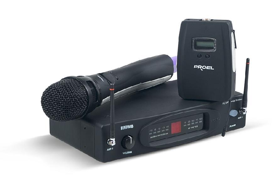
6 Grazie per aver scelto un prodotto PROEL e della fiducia riposta nel nostro marchio, sinonimo di professionalità, accuratezza, elevata qualità ed affidabilità. Tutti i nostri prodotti sono conformi alle normative CE per utilizzazione continua in impianti di diffusione sonora. 2. Descrizione Il sistema radiomicrofonico è composto da 3 parti : ricevitore, trasmettitore a mano WML e trasmettitore tascabile WHL, riponibili nella comoda custodia in ABS in dotazione. Il sistema opera su 100 frequenze selezionabili nella banda MHz (UHF) con tecno logia PLL e contemporaneamente possono funzionare al massimo n 8 sistemi radiomicrofonici. La migliore ricezione del segnale emesso dal trasmettitore è costantemente garantita dal sistema Diversity delle antenne in ricezione, controllato tramite un apposito microprocessore. Il ricevitore ha caratteristiche e prestazioni notevolmente evolute, fornendo la massima qualità in ogni tipo di applicazione. E dotato di un ampio LED display in grado di visualizzare la frequenza di lavoro selezionata, l intensità del segnale in radiofrequenza ed il segnale audio in uscita. Il trasmettitore palmare presenta: display con indicazione di carica della batteria, canale, capsula microfonica dinamica, case in materiale plastico antiurto ed antigraffio con antenna trasmittente integrata. Funzionamento con due batterie stilo tipo AA da 1,5V con 8 ore di massima autonomia con uso continuo. Il trasmettitore bodypack presenta: display con indicazione di carica della batteria, canale. Microfoni lavalier ed headset a condensatore a corredo, case in materiale plastico antiurto ed antigraffio con antenna trasmittente integrata. 3. Funzioni E Controlli a) Pannello Frontale AUDIO METER db RF METER 2 1. Interruttore d accensione 2. Display LED AUDIO METER indica lo stato del livello di segnale audio in ingresso. La non accensione dei led indica l assenza di segnale in ingresso. AF METER indica lo stato del livello di segnale a radio frequenza RF. La non accensione dei led indica l assenza di segnale radio. FREQUENCY indica il numero del canale radio in uso 0 / 99. Ogni numero rappresenta una frequenza pre-impostata. 3. Volume Potenziometro per il controllo del volume in uscita dal ricevitore tramite i connettori XLR (bilanciato) e jack ( sbilanciato) posti sul pannello posteriore. 4. Antenna A / B 6
7 b) Pannello Posteriore UP / DOWN Selezione manuale delle frequenze pre-selezionate da 0 a 99 tramite la pressione sui tasti UP e DOWN. 2. Menu Tenendo premuto il pulsante per 1,5 secondi, si attiva la funzione Sq (vedi la sezione squelch Control) 3. LOW MID HI Selezione del livello d uscita del BALANCED OUT. Level: LOW -12dB, MID -6dB, HIGH 0 db. 4. Uscita Audio sbilanciata su Jack 6.3 mono 5. Uscita Audio bilanciata su XLR-M 6. Connettore alimentazione VDC Collegare a questo connettore l alimentatore AC/DC precedentemente collegato alla presa di rete VAC. c) Trasmettitore a Mano 1. Griglia Protegge la capsula microfonica. 2. Display Il display LCD mostra: simbolo d antenna (se TX e RX sono agganciati), frequenza di lavoro, livello di carica della batteria, CANALE, potenza di trasmissione (PL), LOCK. 3. CH/ON Premendo per un secondo questo tasto il trasmettitore si accende, alle successive pressioni si passa ciclicamente alle seguenti funzioni: CHANNEL / PL / LOCK. Per spegnere il trasmettitore premere il tasto per un secondo. 4. SELECT Nella modalità funzioni permette di scegliere i valori. 5. Vano Batterie Svitare il corpo del microfono inserire 2 batterie stilo AA 1,5V o ricaricabili (optional) rispettando la polarità quindi riavvitare. 6. Antenna La copertura dell antenna (ad esempio con le mani), comporta un attenuazione del segnale emesso, con possibile fruscio e perdite del segnale. 7
8 d) Trasmettitore Bodypack 1. Display Il display LCD mostra: simbolo d antenna (se TX e RX sono agganciati), frequenza di lavoro, livello di carica della batteria, CANALE, potenza di trasmissione (PL), LOCK. 2. CH/ON Premendo per un secondo questo tasto il trasmettitore si accende, alle successive pressioni si passa ciclicamente alle seguenti funzioni: CHANNEL / PL / LOCK. Per spegnere il trasmettitore premere il tasto per un secondo. 3. SELECT Nella modalità funzioni permette di scegliere i valori. 4. Jack di carica Per la ricarica delle batterie ricaricabili, collegare il caricabatteria (opzionale) a questo jack. 5. Connettore Mini 4P Collegare il microfono lavalier ed headset a questo connettore. Tramite questo connettore è possibile collegare al trasmettitore una chitarra, un basso una tastiera ecc. Pin 1: Pin 2: Pin 3: massa + 5 V Audio Pin 4: 6. Vano Batterie Aprire il vano e inserire 2 batterie stilo AA 1,5V o ricaricabili (optional) rispettando la polarità, chiudere. 7. Clip Aggancio per cintura. 8. Antenna La copertura dell antenna (ad esempio con le mani), comporta un attenuazione del segnale emesso, con possibili fruscii o perd ite di trasmissione. 8
9 4. Operazioni a) Ricevitore Squelch Control Entrare nella modalità SQUELCH premendo il tasto MENU, il display mostrerà un numero tra 0 e 10 che indica il valore corrente della soglia come riportato dalla tabella: Numero Soglia di Squelch 1 95,0 db 2 91,7 db 3 88,3 db 4 85,0 db 5 81,7 db 6 78,3 db 7 75,0 db 8 71,7 db 9 68,3 db 10 65,0 db AUDIO METER db RF METER Selezionare il livello desiderato con i tasti UP e DOWN, premere il tasto MEM per uscire dalla selezione. Finche il segnale ricevuto ha un livello inferiore alla soglia impostata, il ricevitore resterà silenziato, questa funzione elimina il rumore di fondo nelle pause. Fare attenzione al livello impostato, una soglia troppo elevata rischia di tagliare anche il segnale desiderato. Selezione manuale della frequenza Premendo il tasto UP / DOWN è possibile scegliere la frequenza desiderata mediante i tasti UP e DOWN, memorizzare il canale scelto mediante il tasto MEM. b) Trasmettitore WHL / WML Ch/On Premendo per un secondo questo tasto il trasmettitore si accende mostrando la frequenza corrente e il livello di carica della batteria, alle successive pressioni si passa ciclicamente alle seguenti funzioni: CHANNEL - PL - LOCK / UNLOCK. Per spegnere il trasmettitore premere il tasto per un secondo. Selezione della frequenza Entrare nella modalità CANALE premendo il tasto CH/ON, il display mostrerà il simbolo CH seguito dal valore corrente di canale, mediante il tasto SELECT selezionare il canale desiderato. Dopo alcuni secondi dall ultima digitazione il display si riporta sulla schermata iniziale. Selezione del livello di potenza RF Entrare nella modalità POTENZA premendo tre volte il tasto CH/ON, il display mostrerà il simbolo PL seguito dal livello di potenza corrente, mediante il tasto SELECT selezionare il livello desiderato. Dopo alcuni secondi dall ultima digitazione il display si riporta sulla schermata iniziale. 9

10 Funzione Lock Entrare nella modalità Look/unlock premendo quattro volte il tasto CH/ON, il display mostrerà Look o unlock a seconda di quale è settato correntemente, mediante il tasto SELECT selezionare o deselezionare il blocco. Dopo alcuni secondi dall ultima digitazione il display si riporta sulla schermata iniziale. Quando il Trasmettitore è bloccato il dispositivo permette la scansione delle funzioni mostrando sul display i parametri correnti, ma non permette la loro modifica le uniche operazioni consentite sono: accensione, spegnimento, impostazione del MUTE e deselezione del lock. Funzione Mute Premendo per più di un secondo il tasto SELECT, viene attivata la funzione MUTE e la scritta mute compare in maniera permanente sul display. Premendo nuovamente il tasto SELECT la scritta scompare e la funzione viene deselezionata. Quando la funzione Mute è attiva il trasmettitore non trasmette. Batterie Quando le batterie sono scariche l indicatore di livello batterie lampeggia, sostituire (o ricaricare, nel caso di batterie ricaricabili) le batterie. Utilizzare batterie stilo tipo AA 1,5V. 5. Installazione Collegare l uscita del ricevitore ad un mixer/amplificatore, utilizzando l uscita bilanciata o sbilanciata a seconda dei casi. Connessione di tipo bilanciata Connessione di tipo sbilanciata Connessione di tipo sbilanciato con jack mono Connessione RCA Accendere il ricevitore Inserire le batterie nel trasmettitore e accenderlo. Selezionare manualmente la stessa frequenza sul ricevitore e sul trasmettitore. 10
11 6. Tabella Frequenze ( mhz) CH 0 CH 1 CH 2 CH 3 CH 4 CH 5 CH 6 CH 7 CH8 CH 9 CH 10 CH CH 12 CH 13 CH 14 CH 15 CH 16 CH 17 CH 18 CH 19 CH 20 CH 21 CH 22 CH CH 24 CH 25 CH 26 CH 27 CH 28 CH 28 CH 30 CH 31 CH 32 CH 33 CH 34 CH CH 36 CH 37 CH 38 CH 39 CH 40 CH 41 CH 42 CH 43 CH 44 CH 45 CH 46 CH CH 48 CH 49 CH 50 CH 51 CH 52 CH 53 CH 54 CH 55 CH 56 CH 57 CH 58 CH CH 60 CH 61 CH 62 CH 63 CH 64 CH 65 CH 66 CH 67 CH 68 CH 69 CH 70 CH CH 72 CH 73 CH 74 CH 75 CH 76 CH 77 CH 78 CH 79 CH 80 CH 81 CH 82 CH CH 84 CH 85 CH 86 CH 87 CH 88 CH 89 CH 90 CH 91 CH 92 CH 93 CH 94 CH CH 96 CH 97 CH 98 CH Nel caso di più sistemi radiomicrofonici che lavorano contemporaneamente, per evitare interferenze, utilizzare le seguenti frequenze: 7. Caratteristiche Tecniche CH FREQ. CH CH CH CH CH CH CH CH CH CH MODEL Channel Frequency band: Receiver type: Frequency response: Frequency stability: T.H.D: Modulation mode S/N Ratio Dynamic RF sensitivity Audio output Power Supply Dimensions (WxDxH) Weight Multi-channels, up 8 frequency preset for each frequency band UHF MHz PLL UHF Synthesized 50Hz - 15KHz (-3dB) 0,005% (-10 C - 50 C) < 0,8% 1KHZ FM (F3E) > 90dB >100dB -100dBm/30dB SINAD 250 mv Symmetrical 750 mv Asymmetrical DC 12V-500 ma 230 Vca adaptor 210 mm x 156 mm x 44 mm 0,95Kg 11
12 MODEL WHL Trasmission mode PLL Multi-channel, up 100 frequency preset for each frequency band Frequency band: UHF MHz Frequency response: 50Hz - 15KHz (-3dB) Frequency stability: 0,005% (-10 C - 50 C) T.H.D: < 0,8% 1KHZ Modulation mode FM (F3E) RF Output power max 50mW (adjustable 3 levels) Dynamic >100dB Tone Frequency KHz Max deviaton +/-35KHz Battery AA type x 2 Microphone type Hcm38 ( optional ) Dimensions (WxDxH) 66 mm. x 103 mm. x 23 mm Weight 0,2Kg - MODEL WMP Trasmission mode PLL Multi-channels, up 100 frequency preset for each frequency band Frequency band: UHF MHz Frequency response: 50Hz - 15KHz (-3dB) Frequency stability: 0,005% (-10 C - 50 C) T.H.D: < 0,8% 1KHZ Modulation mode FM (F3E) RF Output power Max 10 mw Dynamic >100dB Tone Frequency KHz Max deviaton +/-35KHz Battery AA type x 2 Microphone type Dynamic cardiod Dimensions (WxDxH) 277 mm x 36,5 mm diameter Weight 0,2Kg AVVERTENZA Questo apparecchio radio è inteso per uso professionale nell ambito dell intrattenimento e applicazioni similari. Questo apparecchio potrebbe essere in grado di funzionare a frequenze non autorizzate nella regione in cui si trova l utente. Si consiglia di rivolgersi alle autorità competenti per ottenere le informazioni necessarie relative alle frequenze autorizzate nella propria regione per i sistemi radiomicrofonici. In alcuni casi potrebbe essere necessaria una licenza ministeriale per l uso di questo apparecchio.per i possibili requisiti rivolgersi alle autorità competenti. L utente si assume l esclusiva responsabilità per l acquisizione della licenza delle attrezzature senza fili e la linceziabilità dipende dalla classificazione e dall applicazione dell utente e dalla frequenza selezionata. Ai sensi del D. Lgs. 269/2001 art.6 comma 3 Informazioni sulla conformità alla direttiva R&TTE Con la presente Proel S.p.A. dichiara che questo sistema radiomicrofonico è conforme ai requisiti essenziali ed alle altre disposizioni pertinenti stabilite dalla direttiva 1995/5 / CE. La dichiarazione di conformità può essere consultata sul sito: Prodotto notificato in Italia. il prodotto è conforme alla Direttiva 89/336/CEE (Compatibilità Elettromagnetica) e successive modifiche 92/31/CEE e 93/68/CEE. inoltre, è conforme alla Direttiva 73/23/CEE (Bassa Tensione) e successive modifiche 93/68/CEE. La Proel SpA persegue una politica di costante ricerca e sviluppo, di conseguenza si riserva il diritto di apportare miglioramenti ai prodotti esistenti, senza preavviso e in qualunque momento. La Proel SpA non assume alcuna responsabilità sull uso ed alle applicazioni dei prodotti o circuiti riportati su questo manuale. PROEL S.p.A. Via alla Ruenia 37/ Sant Omero (Te) Italy Tel: Fax: info@proel.com 12
13 1. Safety Instructions Country code Codice paese Stage wireless microphone systems Frequency range Frequenze autorizzate FR,PL,HU,BE,CH,IT,NL,LU,DE,FIN , IT , all other countries * * please your national frequency authority for information on available legal frequencies and legal use CE CAUTION: To reduce the risk of electric shock do not the remove cover or back panel. No user serviceable parts inside. Refer servicing to qualified personnel only. WARNING: To reduce the risk of fire or electric shock, do not expose this apparatus to rain or moisture. This symbol is intended to alert the user of the presence of un-insulated dangerous voltage within the product enclosure that may be of sufficient magnitude to constitute a risk of electric shock to persons. This symbol is intended to alert the user of the presence of important operating and maintenance (servicing) instruction in the literature accompanying the appliance. Please carefully read the owner s manual. INSTRUCTIONS All safety and operating instructions should be read before the product is operated. Retain these instructions All safety and operating instructions should be retained for future reference. This owner s manual should be considered as a part of the product and it must accompany it every time, and delivered to the new user when this product is sold. In this way the new owner will be aware of all the installation, operating and safety instructions. Heed all warnings All warnings on the product and in owner s manual should be adhered to. Follow all instructions All operating and user s instructions must be followed. Sentences preceded by symbol contain important safety instruction. Please read it carefully. DETAILED SAFETY INSTRUCTIONS Water and moisture This apparatus should not be used near water (i.e. bathtub, kitchen sink, swimming pools, etc.). Heat This apparatus should be placed away from heat sources, like radiators, heat registers, stoves or other products (including amplifiers) that produce heat. Power sources This apparatus should only be connected to power source type specified in this owner s manual or on the unit. 13
14 If the supplied AC power cable plug is different from the wall socket, please contact an electrician to change the AC power plug. Grounding or Polarization: All precautions must be observed to do not defeat grounding or polarization. Unit metal parts are grounded through the AC power cord. If the AC power outlet doesn t have grounding, consult an electrician for outlet grounding. 14
15 Power cord protection The power cord should be positioned in a way it will not be stepped on or pinched by items placed upon or against it, paying particular attention to cable connected to the plugs, sockets and wall outlets. Cleaning: The unit can be cleaned with compressed air or with a soft damp cloth. Do not clean the unit with solvents such as trichloroethylene, thinners, alcohol, or other fluids with very strong volatility and flammability. Long periods where the unit is not being used If not used for long periods, the unit should be disconnected from the AC power supply. Objects or liquid entry inside the unit Be careful that no objects fall or liquid is spilled inside the unit through ventilation openings. Safe power line use Hold the plug and the wall outlet while disconnecting the unit from AC power. If the unit will not be used for a long period of time, please unplug the power cord from AC power outlet. To avoid unit power cord damage, please do not strain the AC power cable and do not bundle it. In order to avoid unit power cord damage, please ensure that the power cord is not stepped on or pinched by heavy objects. Unit relocation Before the unit is relocated please ensure the unit is switched off. The power cord must be unplugged from the wall outlet and all connection cables should be disconnected. Do not open this unit Do not attempt to open or to repair this unit by yourself. For any problems not described in this owner s manual, please refer to qualified personnel only or consult PROEL or your National PROEL Distributor. Any improper operation could result in fire or electric shock. Damages requiring services Do not attempt any operations not described in this user s manual. In the following cases please refer to an authorised maintenance centre or skilled personnel: - When the unit works improperly or it does not work at all. - If power cord or plug are damaged. - If liquid has spilled, or objects have fallen into the unit. - If the unit has been exposed to rain. - If the unit does not operate normally or it exhibits a marked change in performance. - If the product has been dropped or it has been damaged in any way. Maintenance The user should not attempt any maintenance operation not described in this user s manual. All maintenance should be carried out by qualified personnel. 15
16 IMPORTANT SAFETY INSTRUCTIONS: Install this unit following owner s manual instructions. Do not install, connect or disconnect power supply when the unit is powered, to avoid electric shock. Do not open the unit: there are no user serviceable parts inside. If you detect any strong smell emanating from the unit, immediately turn it off and disconnect the AC power cord. Do not block the unit ventilation openings. Avoid using this unit in overload for a long period. Do not force the commands (switches, controls, etc.) For safety reason, do not defeat or bypass the grounding connection. Grounding is important for user safety. Only use connectors and accessories suggested by the manufacturer.. This unit should be placed in a rack and kept far from: - Wet / humid areas - Direct exposure to heat sources (like sun light) - Non properly ventilated places Disconnect the power cord during storms or when the unit is not being used. In order to prevent fire and electric shock risks, it is necessary to keep the unit far from liquids. Please do not put cups, vases or other object containing liquids over the unit. In case of interference from source signal, the THD value will raise over 10%. Do not place this unit in confined spaces. PROEL S.p.A. is not responsible for any damage that occurs due to a incorrect installation of the unit. 16
17 Thank you for choosing this PROEL product and for your trust in our brand, synonymous of professionalism, accuracy, high quality and reliability. All our products are CE approved and designed for continuous use in professional systems. 2. Description The Wireless Microphone system features 3 units: The receiver, WMP handheld transmitter and WHL body pack transmitter. A carrying case is included. This Wireless system operating frequency range covers 100 UHF different frequencies to be selected amongst the following UHF frequency band MHz (UHF) thanks to PLL technology. Up to a maximum of 8 systems can operate contemporaneously. The available Diversity Antenna constantly grants the better transmitter signal thanks to an appropriate microprocessor monitoring. The receiver provides a high quality reproduction in many applications and it is hosted in a ½ rack unit metal case (optional fixing kit is available for mounting in a standard 19 rack). The receiver is equipped with a LED display showing the operating frequency, signal intensity and audio output signal. The transmitter s LCD displays the battery charge level and the channel frequency. Microphone transmitter is a dynamic cardioid. Two antenna, a plastic anti-scratch case and two AA 1,5 V batteries with 8 hours of autonomy re included. The LCD on the body-pack transmitter indicates the battery charge level, frequency channel. Headset condenser microphone provided, the body pack transmitter is supplied with a plastic, anti-scratch case plus two antenna and two AA 1,5 V batteries with 8 hours autonomy. 3. Functions and Controls a) Front Panel AUDIO METER db RF METER 1. ON/OFF switch 2. Display Indicated RF signal level, Audio frequency level, the channel no. and the antenna in best signal receipt 3. Volume 4. Antenna A/B The antennas can be fully rotated for optimum placement. 2 17
18 b) Rear Panel UP / DOWN In manual selecting mode, use the Up key to scan the frequency presets from 0 to 99 and Down key from 99 to Menu Keep pressing the Menu key for 1,5 seconds, it comes to the SQ mode. 3. LOW MID HI This key controls the AF output Balanced level. Set the key to Low position for 12db output, Mid for 6db, High for 0db Jack Mono Unbalanced audio output Use a jack mono 6.3 and a shielded unbalance cable. 5. XLR Balanced Audio output The jack mono output should only be used if the distance between the rmw10 and the mixer / amplifier is not very long. Use a jack mono 6.3 and a shielded unbalance cable. 6. VDC Power Connector Connect AC/DC power supply to VDC and ensure to connect previously to the main power supply Vac. c) Handheld Transmitter WML 1. Grille for microphone capsule protection 2. Display Indicates the antenna symbol ( when TX and RX are coupled), operating frequency, battery charge level Channel, (PL) transmission power, LOCK 3. CH/ON Pressing for one second to switch on the transmitter. The transmitter displays the current frequency, the battery charge level. Press again to pass in a cyclic mode the following functions: CHANNEL / PL / LOCK. To disable the transmitter press and keep pressing for one second. 4. SELECT Functions mode operating allows value selection. 5. Battery location Unscrew microphone body to insert 2 AA 1,5 V batteries (optional rechargeable) respecting the polarity. 6. Antenna If the antenna is covered (by hands for example), the signal can be attenuated with the possibility of signal loss or noise. 18
19 d) Body Pack Transmitter WHL 1. Display LCD displays: antenna symbol ( when TX and RX are couplet), operating frequency, charge battery level, CHANNEL, power transmission (PL), LOCK 2. CH/ON Pressing for one second to switch on the transmitter. The transmitter displays the current frequency, the battery charge level. Press again to pass in a cyclic mode the following functions: CHANNEL / PL / LOCK. To disable the transmitter press and keep pressing for one second 3. SELECT Functions mode allows value selection. 4. Jack for battery recharge purposes To charge rechargeable batteries, connect the battery charger (optional) to this jack input. 5. Mini 4P connector Connect the clip microphone and headset to this connector: guitar, bass, keyboard etc... can be connected to this input. Pin 1: Pin 2: Pin 3: massa + 5 V Audio Pin 4: 6. Battery compartment Open the battery housing and insert 2 batteries AA 1,5V or rechargeable batteries (optional) respecting the polarity. 7. Clip 8. Antenna If the antenna is covered (by hands for example), the signal can be attenuated with the possibility of signal loss or noise. 19
20 4. Operation a) Receiver Squelch Control Enter SQUELCH mode pressing the MENU key, the symbol with the current level value is displayed: Number Squelch threshold 1 95,0 db 2 91,7 db 3 88,3 db 4 85,0 db 5 81,7 db 6 78,3 db 7 75,0 db 8 71,7 db 9 68,3 db 10 65,0 db AUDIO METER db RF METER Select level using key UP and DOWN, confirm pressing with MEM key. If the input signal is below the setting level, the receiver is muted, this function eliminates background noise during pause time. Ensure to set such level to avoid to eliminate the signal. Manual frequency selection Pressing key UP / DOWN for select the channel, using MEM key for exit. b) Transmitter WHL/WML Ch/on Press for one second to switch on the Transmitter. Transmitter displays the current frequency, the battery charge level. Press newly to pass in a cyclic mode to the following functions: CHANNEL - PL - LOCK / UNLOCK. To disable the transmitter press and keep pressing for one second. Frequency selection Enter CHANNEL mode pressing key CH/ON, CH symbol is displayed along with the current channel value. Using SELECT key to select CHANNEL. Some seconds after the last key press, the display returns to the initial visualisation. RF level Selection Enter POWER mode pressing 3 times key CH/ON, Symbol PL and the current power value are displayed. Use SELECT key to select the output power you need, 0 : the output power is 5dB,1 : the output power is 10dB, 2 : the output power is 15dB. Some seconds after the last key press, the display comes back to the main menu. Lock Function Enter Look/unlock mode pressing 4 times CH/ON key, Symbol look or unlock ( considering the setting selected) are displayed, Using SELECT key to select the setting (look/unlock). Some seconds after the last key press, the display return to the initial visualisation. When the transmitter is blocked, it is possible to perform the functions scan. The display visualise the current setting without allowing the setting modification: the sole available functions setting is: to power on, to switch off, to set MUTE and lock selection. 20
21 Mute function Pressing the select key for more than one second will activate the mute function, the word Mute word displayed. Pressing SELECT again will deactivate the mute function. When MUTE function is active the transmitter does not transmit. Battery When batteries are exhausted, the battery level indicator will light. If rechargeable batteries are used, use AA 1,5V Battery. 5. Installation Connect receiver to a mixer/amplifier, using the balanced or unbalanced output as follows: Balanced connection Unbalanced connection Unbalanced connection with Mono jack RCA connection Connect adaptor AC/DC to and to the main power supply socket. Switch on the receiver. Insert the batteries in the transmitter and switch it on. Select manually the same frequency on the receiver and on the transmitter. 21
22 6. Frequency Table ( mhz) CH 0 CH 1 CH 2 CH 3 CH 4 CH 5 CH 6 CH 7 CH8 CH 9 CH 10 CH CH 12 CH 13 CH 14 CH 15 CH 16 CH 17 CH 18 CH 19 CH 20 CH 21 CH 22 CH CH 24 CH 25 CH 26 CH 27 CH 28 CH 28 CH 30 CH 31 CH 32 CH 33 CH 34 CH CH 36 CH 37 CH 38 CH 39 CH 40 CH 41 CH 42 CH 43 CH 44 CH 45 CH 46 CH CH 48 CH 49 CH 50 CH 51 CH 52 CH 53 CH 54 CH 55 CH 56 CH 57 CH 58 CH CH 60 CH 61 CH 62 CH 63 CH 64 CH 65 CH 66 CH 67 CH 68 CH 69 CH 70 CH CH 72 CH 73 CH 74 CH 75 CH 76 CH 77 CH 78 CH 79 CH 80 CH 81 CH 82 CH CH 84 CH 85 CH 86 CH 87 CH 88 CH 89 CH 90 CH 91 CH 92 CH 93 CH 94 CH CH 96 CH 97 CH 98 CH In case several wireless microphone systems are operating contemporaneously and in order to avoid interference, use the following frequencies: CH FREQ. CH CH CH CH CH CH CH CH CH CH Note: Do not use the same frequency for 2 wireless microphone systems. 7. Technical Specifications MODEL Channel Frequency band: Receiver type: Frequency response: Frequency stability: T.H.D: Modulation mode S/N Ratio Dynamic RF sensitivity Audio output Power Supply Dimensions (WxDxH) Weight Multi-channels, up 100 frequency preset for each frequency band UHF MHz PLL UHF Synthesized 50Hz - 15KHz (-3dB) 0,005% (-10 C - 50 C) < 0,8% 1KHZ FM (F3E) > 90dB >100dB -100dBm/30dB SINAD 250 mv Symmetrical 750 mv Asymmetrical DC 12V-500 ma 230 Vca adaptor 210 mm x 156 mm x 44 mm 0,95Kg 22
23 MODEL WHL Trasmission mode PLL Multi-channels, up 100 frequency preset for each frequency band Frequency band: UHF MHz Frequency response: 50Hz - 15KHz (-3dB) Frequency stability: 0,005% (-10 C - 50 C) T.H.D: < 0,8% 1KHZ Modulation mode FM (F3E) RF Output power max 50mW (adjustable 3 levels) Dynamic >100dB Tone Frequency KHz Max deviaton +/-35KHz Battery AA type x 2 Microphone type Hcm38 ( optional ) Dimensions (WxDxH) 66 mm. x 103 mm. x 23 mm Weight 0,2Kg - MODEL WML Trasmission mode PLL Multi-channels, up 100 frequency preset for each frequency band Frequency band: UHF MHz Frequency response: 50Hz - 15KHz (-3dB) Frequency stability: 0,005% (-10 C - 50 C) T.H.D: < 0,8% 1KHZ Modulation mode FM (F3E) RF Output power Max 10 mw Dynamic >100dB Tone Frequency KHz Max deviaton +/-35KHz Battery AA type x 2 Microphone type Dynamic cardiod Dimensions (WxDxH) 277 mm x 36,5 mm diameter Weight 0,2Kg WARNING LICENSING INFORMATION Changes or modifications not expressly approved by Proel S.p.A. could void your authority to operate the equipment. Licensing of wireless microphone equipment is the user s responsibility, and licensability depends on the user s classification and application, and on the selected frequency. Proel strongly urges the user to contact the appropriate telecommunications authority concerning proper licensing, and before choosing and ordering frequencies. IMPORTANT! This equipment may be capable of operating on some frequencies not authorized in your region. Please contact your national authority to obtain information on authorized frequencies for wireless microphone products in your region. The product is in compliance with Directive 89/336/EEC (Electromagnetic Compatibility) and following modifications 92/31/EEC and 93/68/EEC It is also in compliance with Directive 73/23/EEC (Low Voltage) and following modifications 93/68/EEC. PROEL S.p.A hereby, declares that this wireless microphone system complies with the essential requirements and other relevant provisions of Directive 1999/5/EC. Consult local or national radio spectrum authorities for information on possible restrictions or necessary authorizations before using this Short Range Device. PROEL S.p.A. pursues a policy of continuous research and development. PROEL S.p.A. reserves the right to modify product circuitry and appearance at any moment, without prior notice. PROEL S.p.A. Via alla Ruenia 37/ Sant Omero (Te) Italy Tel: Fax: info@proel.com 23
24 PROEL S.p.A. (World Headquarters - Factory) Via alla Ruenia 37/ Sant Omero (Te) Italy Tel: Fax: info@proel.com
RMW10 Wireless System
 Wireless System INDICE 1. Precauzioni d uso... 3 2. Descrizione... 6 3. Funzioni e Controlli... 6 a) Pannello Frontale RMW10... 6 b) Pannello posteriore RMW10... 7 c) Trasmettitore a mano WMP... 7 d) Trasmettitore
ELCART. Manuale di istruzioni/scheda tecnica. Alimentatore Switching 60W UPS 13/26500 (Mod. VIC-60-12UPS)
") PAGINA 1 DI 6 Alimentatore Switching 60W UPS 13/26500 (Mod. VIC-60-12UPS) NOTA! LEGGETE ATTENTAMENTE QUESTO MANUALE DI ISTRUZIONI PRIMA DI INSTALLARE QUESTO ALIMENTATORE. Prima della prova e messa in servizio
PAGINA 1 DI 6 Alimentatore Switching 60W UPS 13/26500 (Mod. VIC-60-12UPS) NOTA! LEGGETE ATTENTAMENTE QUESTO MANUALE DI ISTRUZIONI PRIMA DI INSTALLARE QUESTO ALIMENTATORE. Prima della prova e messa in servizio
RMW10 Wireless System
 Wireless System Indice / index 1. Precauzioni D uso... 3 2. Descrizione... 6 3. Funzioni E Controlli... 6 Pannello Frontale...6 Pannello posteriore...7 Trasmettitore a mano WMP...7 Trasmettitore bodypack
Trasmissione a distanza
 Trasmissione a distanza M AK2 Kit trasmettitore ricevitore Miniature wireless kit Manuale Operatore Operator Manual Microvideo s.r.l. Via Dei Castani, scn 64014 Martinsicuro (TE) Italy Tel ++39 0861 762259
MANUALE UTENTE. Amplificatore PA Integrato AMP03
 MANUALE UTENTE Amplificatore PA Integrato AMP03 Grazie per aver scelto un nostro prodotto e della fiducia riposta nel nostro marchio, sinonimo di professionalità, accuratezza e di elevata qualità. 1. PRECAUZIONI
UNITÀ DIMMER DI POTENZA PLDM6K
 MANUALE UTENTE USER S MANUAL UNITÀ DIMMER DI POTENZA PLDM6K Rev. 09/2006 INDICE GENERALE... 3 CARATTERISTICHE TECNICHE... 3 PRECAUZIONI PRIMA DELL INSTALLAZIONE... 3 CONTROLLO E FUNZIONI... 4 PANNELLI...
USER MANUAL MANUALE D USO BE Additional 12-zone. keyboard for BM 2006 paging microphone. - - Tastiera addizionale per base microfonica BM 2006
 USER MANUAL MANUALE D USO -- Additional 12-zone BE 2012 keyboard for BM 2006 paging microphone - - Tastiera addizionale per base microfonica BM 2006 INDEX INDICE ENGLISH SAFETY PRECAUTIONS DESCRIPTION
RM100 Wireless System
 Wireless System INDICE Precauzioni d uso... 3 Descrizione... 5 Ricevitore RM100 (fig.1)... 5 Trasmettitore a mano WTX201 (fig. 2)... 5 Trasmettitore bodypack WHX21 (fig.3)... 6 INDEX Safety Instructions...
MANUALE UTENTE - INSTRUCTION MANUAL. Unità di Espansione Expansion units EXBM8X8
 MANUALE UTENTE - INSTRUCTION MANUAL Unità di Espansione Expansion units EXBM8X8 2 INDICE 1. PRECAUZIONI D USO... 4 2. DESCRIZIONE... 5 3. COLLEGAMENTO DELLE UNITA DI ESPANSIONE... 5 3 1. PRECAUZIONI D
Temperatura di Lavoro / Working Temperature. Distanza di controllo/ Distance control
 Nauled Once upon a light Rev. 03/2018 cod. NC-T2.4-02 DIMMER LED CCT (TEMPERATURA DI COLORE REGOLABILE) CON TELECOMANDO TOUCH 2.4G RF (4 ZONE) / CCT (COLOR TEMPERATURE ADJUSTABLE) LED DIMMER WITH 2.4G
RM200 RM200. Wireless System
 RM200 Wireless System INDICE Precauzioni d uso...3 Descrizione...5 Frequenze disponibili...5 Ricevitore RM200 (fig.1)...5 Trasmettitore a mano WTX201 (fig. 2)...5 Trasmettitore bodypack WHX21 (fig.3)...6
VHF100. Wireless System
 Wireless System INDICE Precauzioni d uso... 3 Descrizione... 5 Ricevitore VH100 (fig.1)... 5 Trasmettitore a mano VH1M (fig. 2)... 5 Trasmettitore bodypack VH1H (fig.3)... 6 Safety Instructions... 6 Description...
SISTEMA DI ILLUMINAZIONE PER VERRICELLI WINDLASS LIGHTING SYSTEM
 Istruzioni per l uso Instructions for use SISTEMA DI ILLUMINAZIONE PER VERRICELLI WINDLASS LIGHTING SYSTEM WLS WINDLASS LIGHTING SYSTEM - 1 - Rev.01-2013 Italiano SISTEMA DI ILLUMINAZIONE PER VERRICELLI
MANUALE DI ISTRUZIONI
 Cantatooth ONE000004 - ONE000006 MANUALE DI ISTRUZIONI INSTRUCTIONS MANUAL 2 cantatooth 1. DESCRIZIONE PRODOTTO Parti Microfono Controllo Volume Controllo Riverbero Power On/Off 8.35in Cassa 2.83in Accessori
MANUALE UTENTE - INSTRUCTION MANUAL. Controlli Remoti Remote Controls R88
 MANUALE UTENTE - INSTRUCTION MANUAL Controlli Remoti Remote Controls R88 2 INDICE 1. PRECAUZIONI D USO... 4 2. DESCRIZIONE... 5 3. PANNELLO FRONTALE E POSTERIORE... 5 4. CARATTERISTICHE TECNICHE... 6 3
TFT LCD -5 /COL Monitor a colori LCD TFT 5 senza fili 2.4 GHz 2.4 GHz Wireless CCD 5" TFT color LCD monitor
 I GB TFT LCD -5 /COL Monitor a colori LCD TFT 5 senza fili 2.4 GHz 2.4 GHz Wireless CCD 5" TFT color LCD monitor IS1168-AA Manuale di Installazione Installation manual 1/8 TFT LCD-5 /COL GUIDA DI INSTALLAZIONE
Manuale utente - User manual. 6 CH. LED Control
 Manuale utente - User manual ATTENZIONE: Prima di usare questi apparecchi, leggere attentamente le istruzioni che seguono. Spotlight srl non potrà essere ritenuta responsabile di danni derivanti dalla
Wireless DMX 512 RECEIVER
 Wi D PEN Pulsante Presa alimentazione Connettore XLR 3/5 poli Led RGB Wireless DMX 512 RECEIVER! I MANUALE DI INSTALLAZIONE ED USO 1.1 CONNESSIONE INGRESSO DI ALIMENTAZIONE I Inserire fino in fondo il
BODYPACK DIGITALE E MICROFONO AD ARCHETTO PER ATOMIC4DJ UHF 702. Modello Atomic4Dj Bodypack Headset UHF-702 MANUALE OPERATIVO
 BODYPACK DIGITALE E MICROFONO AD ARCHETTO PER ATOMIC4DJ UHF 702 Modello 23156 Atomic4Dj Bodypack Headset UHF-702 MANUALE OPERATIVO Le informazioni contenute in questo documento sono state attentamente
DMX. Wireless DMX 512 TRANSMITTER MANUALE DI INSTALLAZIONE ED USO
 Wi DMX R Wireless DMX 512 TRANSMTTER MANUALE D NSTALLAZONE ED USO DESCRZONE PANNELL 4 1 2 5 1 Connettore antenna SMA 2 ngresso alimentatore 5 Vdc 650 ma (fornito) Led blu : Lampeggio lento : Trasmettitore
MANUALE UTENTE - INSTRUCTION MANUAL. Controlli Remoti Remote Controls LOC02
 MANUALE UTENTE - INSTRUCTION MANUAL Controlli Remoti Remote Controls LOC02 2 INDICE 1. PRECAUZIONI D USO... 4 2. DESCRIZIONE... 5 3. PANNELLO FRONTALE E POSTERIORE... 5 4. CARATTERISTICHE TECNICHE... 6
TLR02. Dimmer per Led in tensione costante a 4 canali
 TLR02 Dimmer per Led in tensione costante a 4 canali DATI TECNICI Alimentazione Uscita Tipo di carico 12-24 Vdc Carico max 10A: 90 W (12Vdc 3Ch); 120 W (12Vdc 4Ch) 180 W (24Vdc 3Ch); 240 W (24Vdc 4Ch)
RADIOMICROFONO PROFESSIONALE PRO-SHOW VHF 252 DOPPIO TRASMETTITORE. Modello PRO-SHOW VHF VHF 252 MANUALE D USO
 RADIOMICROFONO PROFESSIONALE PRO-SHOW VHF 252 DOPPIO TRASMETTITORE Modello PRO-SHOW VHF VHF 252 MANUALE D USO INDICE Precauzioni d uso...3 Istruzioni di sicurezza 4 Descrizione...6 Set up...8 Avvertenze...9
Smoke machine 400W PLFD400EL
 Smoke machine 400W PLFD400EL MANUALE UTENTE USER MANUAL 1 Rev. 01-06/13 Nel caso in cui si noti una scarsa uscita di fumo, o la pompa sia particolarmente rumorosa, o non venga vaporizzato il fumo, scollegare
BPTECHNOLOGY. Manuale d uso BE-5014B - BE5014BL Kit radio microfono UHF true diversity
 Manuale d uso BE-5014B - BE5014BL Kit radio microfono UF true diversity BPTECNOLOGY UF DIVERSITY RECEIVER T-514 5 10 15 20 25-30 -25-20 -15-10 30-5 35 40 0 PEAK BPTECNOLOGY GENERALITÀ Grazie per aver scelto
PLL ALARM CLOCK RADIO Model : FRA252
 PLL ALARM CLOCK RADIO Model : FRA252 IT MANUALE D'USO IT MANUALE D'USO ATTENZIONE: PER EVITARE IL RISCHIO DI INCENDIO O FOLGORAZIONE NON ESPORRE L'APPARECCHIIO A PIOGGIA O UMIDITÀ. CAUTION Questo simbolo,
GM905 - GM905H - GM905HP
 GM90 - GM90H - GM90HP Radiomicrofono professionale - VHF > > > > > > > > > > > > > > > > > > > Prime operazioni Prima di installare il radiomicrofono, fare attenzione ad alcune cose primarie: - assicurarsi
SRT064 BTH SRT051 BTH SRT052 BTH
 KIT FOR TRUCK BRAKE TESTERS SRT051 BTH SRT052 BTH OPERATOR S MANUAL SRT064BTH SRT051BTH SRT052BTH CONTENTS 1. INTRODUCTION...1 2. Description of SRT064BTH Kit...2 3. Description of SRT051BTH Kit...2 4.
Attuatore a relè Manuale di istruzioni
 Attuatore a relè Manuale di istruzioni www.ecodhome.com 1 Sommario 3 Introduzione 4 Descrizione e specifiche prodotto 5 Installazione 6 Funzionamento 6 Garanzia 2 Introduzione SmartDHOME vi ringrazia per
DIMMER LED CON TELECOMANDO TOUCH 2.4G RF (4 ZONE) / LED DIMMER WITH 2.4G RF TOUCH REMOTE (4 ZONE)
 / LED DIMMER WITH 2.4G RF TOUCH REMOTE (4 ZONE)") Nauled Once upon a light Rev. 03/2018 cod. NC-T2.4-01 DIMMER LED CON TELECOMANDO TOUCH 2.4G RF (4 ZONE) / LED DIMMER WITH 2.4G RF TOUCH REMOTE (4 ZONE) Questo led dimmer con telecomando touch 2.4G RF a
Nauled Once upon a light Rev. 03/2018 cod. NC-T2.4-01 DIMMER LED CON TELECOMANDO TOUCH 2.4G RF (4 ZONE) / LED DIMMER WITH 2.4G RF TOUCH REMOTE (4 ZONE) Questo led dimmer con telecomando touch 2.4G RF a
MANUALE OPERATIVO GM GM9781H. Radiomicrofono professionale - UHF > > > > > > > > > > > > > > > > > > >
 GM978 - GM978H Radiomicrofono professionale - UHF > > > > > > > > > > > > > > > > > > > Prime operazioni Prima di installare il radiomicrofono, fare attenzione ad alcune cose primarie: - assicurarsi che
ISTRUZIONI DI MONTAGGIO / OPERATION INSTRUCTION
 ISTRUZIOI DI MOTAGGIO / OPERATIO ISTRUCTIO BOIE e CYDE lampada a sospensione / hanging lamp B01; C01; B11; C11; B21; C21 A) installazione e la manutenzione va eseguita ad apparecchio spento. Tutte le operazioni
ISTRUZIONI DI MONTAGGIO / OPERATION INSTRUCTION
 ISTRUZIOI DI MOTAGGIO / OPERATIO ISTRUCTIO ROMEO e GIUIETTA lampada a sospensione / hanging lamp RM01; G01; RM11; G11; RM21; G21 A) installazione e la manutenzione va eseguita ad apparecchio spento. Tutte
MONITOR A COLORI 14 con selettore 2 ingressi (37CM) Mod. LEE-130M2 Cod Manuale di utilizzo
 Mod. LEE-130M2 Cod Manuale di utilizzo") MONITOR A COLORI 14 con selettore 2 ingressi (37CM) Mod. LEE-130M2 Cod. 559591002 Manuale di utilizzo Leggere attentamente il Manuale di Utilizzo, prima dell installazione 1 ATTENZIONE PERICOLO DI SCOSSE
MONITOR A COLORI 14 con selettore 2 ingressi (37CM) Mod. LEE-130M2 Cod. 559591002 Manuale di utilizzo Leggere attentamente il Manuale di Utilizzo, prima dell installazione 1 ATTENZIONE PERICOLO DI SCOSSE
MANUALE UTENTE USER S MANUAL. MEG 10 Megafono - Megaphone
 MANUALE UTENTE USER S MANUAL MEG 10 Megafono - Megaphone Grazie per averci accordato la Vostra fiducia scegliendo un prodotto PROEL, sinonimo di professionalità, accuratezza ed elevata qualità. Descrizione
MANUALE UTENTE - INSTRUCTION MANUAL. Ripartitore quadruplo di antenne 4 way Antenna Splitter UHFSPLITAL
 MANUALE UTENTE - INSTRUCTION MANUAL Ripartitore quadruplo di antenne 4 way Antenna Splitter UHFSPLITAL 2 INDICE 1. PRECAUZIONI D USO... 4 2. DESCRIZIONE... 6 3. FUNZIONI E CONTROLLI... 6 4. INSTALLAZIONE...
MANUALE UTENTE / INSTRUCTION MANUAL TXTOUR - RXTOUR. Sistema per visite guidate Guided tours system
 MANUALE UTENTE / INSTRUCTION MANUAL TXTOUR - RXTOUR Sistema per visite guidate Guided tours system 2 Indice 1. PRECAUZIONI D USO... 4 2. DESCRIZIONE... 6 3. FUNZIONI E CONTROLLI RICEVITORE - RXTOUR...
BM102. Postazione microfonica da tavolo Desk call station MANUALE UTENTE USER S MANUAL
 BM102 Postazione microfonica da tavolo Desk call station MANUALE UTENTE USER S MANUAL SOMMARIO 1. PRECAUZIONI D USO... 3 2. DESCRIZIONE... 5 3. DESCRIZIONE DELLE CONNESSIONI... 6 4. CABLAGGIO ALL AMPLIFICATORE...
LD WSECO16 USER S MANUAL BEDIENUNGSANLEITUNG MANUEL D UTILISATION MANUAL DE USUARIO INSTRUKCJA OBSŁUGI MANUALE D USO UHF DIVERSITY WIRELESS SYSTEM
 1 USER S MANUAL BEDIENUNGSANLEITUNG MANUEL D UTILISATION MANUAL DE USUARIO INSTRUKCJA OBSŁUGI MANUALE D USO UHF Bodypack Transmitter dbv +6 +3 0 A B IR ASC SYSTEM IR 4 8 12-5 A F -3 15 LD WSECO16 UHF DIVERSITY
USER MANUAL 2AMIN521VS
 USER MANUAL 2AMIN521VS SUBJECT INDEX: DESCRIPTION TECHNICAL SPECIFICATION FUNCTIONAL DESCRIPTION DEVICE POWER SUPPLY AND CONNECTION TO THE LED MODULE SINGLE POWER SUPPLY MODE MULTIPLE POWER SUPPLY MODE
MANUALE UTENTE USER S MANUAL CS3TW. Diffusore da soffitto in acciaio - Steel ceiling speaker
 MANUALE UTENTE USER S MANUAL CS3TW Diffusore da soffitto in acciaio - Steel ceiling speaker Grazie per averci accordato la Vostra fiducia scegliendo un prodotto PROEL, sinonimo di professionalità, accuratezza
KN-MICW310 KN-MICW CANALI. Sistema microfonico senza fili in banda UHF MANUALE ITALIANO.
 KN-MICW30 KN-MICW320 50 CANALI Sistema microfonico senza fili in banda UHF MANUALE www.konigelektronic.info ITALIANO 0336 DESCRIZIONE DEL RICEVITORE: INTRODUZIONE: Questo sistema microfonico senza fili
Foglio Integrativo del manuale Serie Trivalente
 Foglio Integrativo del manuale Serie Trivalente AVVERTENZE GENERALI! Questa apparecchiatura deve essere usata utilizzando esclusivamente gas GPL G0/G (butano/propano) alla pressione di 8-0/7 mbar IT COMANDI!
MANUALE UTENTE USER S MANUAL. MEG 25 Megafono - Megaphone
 MANUALE UTENTE USER S MANUAL MEG 25 Megafono - Megaphone Grazie per averci accordato la Vostra fiducia scegliendo un prodotto PROEL, sinonimo di professionalità, accuratezza ed elevata qualità. Descrizione
Importante: istruzioni per la sicurezza
 Importante: istruzioni per la sicurezza IL SIMBOLO CON UN FULMINE FRECCIA, ENTRO UN TRIANGOLO EQUILATERO, AVVERTE L UTILIZZATORE DELLA PRESENZA DI UNA PERICOLOSA ALTA TENSIONE, SENZA ISOLAMENTO ELETTRICO,
RADIOMICROFONO PROFESSIONALE PRO-SHOW VHF 452. Modello PRO-SHOW VHF 452 USER MANUAL
 RADIOMICROFONO PROFESSIONALE PRO-SHOW VHF 452 Modello PRO-SHOW VHF 452 USER MANUAL INDICE Precauzioni d uso...3 Istruzioni di sicurezza 4 Descrizione...7 Set up....10 Avvertenze...11 Specifiche tecniche...11
MANUALE UTENTE - INSTRUCTION MANUAL. Roccia Sonora Sound Stone FGS10
 MANUALE UTENTE - INSTRUCTION MANUAL Roccia Sonora Sound Stone FGS10 2 INDICE 1. PRECAUZIONI D USO... 4 2. DESCRIZIONE... 4 3. INSTALLAZIONE... 5 4. CONTENUTO DELLA CONFEZIONE... 6 5. CARATTERISTICHE TECNICHE...
D D S Application Example
 MAD E IN ITALY DDS889 è un kit di due moduli elettronici sviluppati per lampade alimentate a batterie, questo kit prevede un modulo da installare nella l lampada portatile, ed un modulo come base per la
Attuatore a relè Manuale di istruzioni
 Attuatore a relè Manuale di istruzioni www.ecodhome.com www.myvirtuosohome.com 1 Sommario 3 Introduzione 4 Descrizione e specifiche prodotto 5 Installazione 9 Funzionamento 9 Garanzia 2 Introduzione SmartDHOME
User Manual. Rev Date: 31/05/2018
 Size / Misure 8 50 500 60 150 POWER IN DMX IN DMX OUT 9 4. POWER+DMX out cable + M8 Female Connector 16,80 Connection kit included with the Startline cable / Kit di connessione compreso alla startline
1CPP PORTAPRESE BASCULANTE BACKFLIP POWER SOCKET HOLDER. Manuale d installazione e uso Installation and use manual
 1CPP PORTAPRESE BASCULANTE BACKFLIP POWER SOCKET HOLDER Manuale d installazione e uso Installation and use manual Complimenti per aver acquistato una apparecchiatura Barazza! Questa è un apparecchiatura
MANUALE UTENTE USER S MANUAL CSE1T. Diffusore da soffitto in ABS ABS ceiling speaker
 MANUALE UTENTE USER S MANUAL CSE1T Diffusore da soffitto in ABS ABS ceiling speaker Grazie per averci accordato la Vostra fiducia scegliendo un prodotto PROEL, sinonimo di professionalità, accuratezza
MANUALE OPERATIVO / INSTRUCTION MANUAL IM200-IU v1.3 CT / CTD CT / CTD. Toroidal current transformers. Trasformatori di corrente toroidali. pag.
 MANUALE OPERATIVO / INSTRUCTION MANUAL IM200-IU v1.3 CT / CTD Trasformatori di corrente toroidali CT / CTD Toroidal current transformers pag. 1 / 5 ATTENZIONE!!! Leggere attentamente il manuale prima dell
ISTRUZIONI PER L INSTALLAZIONE E USO INSTALLATION AND USE INSTRUCTION
 ISTRUZIONI PER L INSTALLAZIONE E USO INSTALLATION AND USE INSTRUCTION Cod. 3890 Staffa a pantografo per videowall con chiusura a spinta Pantograph videowall with quick lock push system ATTENZIONE Per un
INSTALLAZIONE INSTALLATION
 INSTALLAZIONE INSTALLATION KIT SOFFIONI MySlim A CONTROSOFFITTO KIT MySlim SHOWER HEADS FOR FALSE CEILING Art. KIT00006 AVVERTENZE: L impianto deve essere effettuato da personale autorizzato, certificato
TRF. Trasmettitore di peso wireless Weight transmitter wireless
 Trasmettitore di peso wireless Weight transmitter wireless Trasmettitore di peso RF 868 MHz Weight transmitter RF 868 MHz Selezione canale RF e indirizzo di comunicazione tramite DIP- SWITCH Selecting
LD SYSTEMS Win 42 Bph 2
 Cod.Art. : 88206 SISTEMA PER RADIOMICROFONO CON 2 X BELT PACK E 2 X HEADSET A motivo della nuova situazione delineatasi dal 2015 nel settore delle autorizzazioni per l'impiego di sistemi radio, LD Systems
RADIOMICROFONO PROFESSIONALE PRO-SHOW VHF 250. Model PRO-SHOW VHF VHF 250 USER MANUAL
 RADIOMICROFONO PROFESSIONALE PRO-SHOW VHF 250 Model PRO-SHOW VHF VHF 250 USER MANUAL INDICE Precauzioni d uso...3 Istruzioni di sicurezza... 4 Descrizione...6 Set up...9 Avvertenze......9 Specifiche tecniche..
MANUALE UTENTE VIVALDI
 MANUALE UTENTE VIVALDI MZ550A Mixer Amplificato 1. Precauzioni di sicurezza Leggere con attenzione le istruzioni contenute in questo manuale prima dell uso. Prestare massima attenzione alle raccomandazioni
controlli di livello capacitivi capacitive levels controls
 controlli di livello capacitivi capacitive levels controls SENSORI CAPACITIVI ALTA TEMPERATURA SC18M-HT/SC30M-HT HIGH TEMPERATURE CAPACITIVE SENSORS SC18M-HT/SC30M-HT MODELS GENERALITÀ GENERAL DETAILS
MANUALE DI ISTRUZIONI. Sistema PA portatile con lettore mp3
 MANUALE DI ISTRUZIONI Sistema PA portatile con lettore mp3 SPECIFICHE Voltaggio in ingresso: AC 110-120V / 60HZ; 220-240V / 50Hz Potenza: 22WMAX; 15WRMS (THD 1%) Risposta in frequenza: 70Hz 50kHz ±3dB
RADIOMICROFONO. U48-H Set. U48-B Set. MANUALE D USO. BestSound s.r.l. C.da Tufarole, Avellino (AV)
") RADIOMICROFONO U48-H Set U48-B Set MANUALE D USO www.bestsound.it BestSound s.r.l. C.da Tufarole, 19-83100 Avellino (AV) e-mail: info@bestsound.it INDICE INTRODUZIONE CARATTERISTICHE DEL RADIOMICROFONO
RADIOMICROFONO U48-H Set U48-B Set MANUALE D USO www.bestsound.it BestSound s.r.l. C.da Tufarole, 19-83100 Avellino (AV) e-mail: info@bestsound.it INDICE INTRODUZIONE CARATTERISTICHE DEL RADIOMICROFONO
LEGEND UPDATE GUIDE INSTALLING LEGEND UPDATE. viscount. Legend Update Guide
 LEGEND UPDATE GUIDE INSTALLING LEGEND UPDATE The Legend series firmware is upgradable via PC. You must first download the Legend Update application from http://www.instruments.com. NB Legend Update is
USER MANUAL MANUALE D USO AC AD2405 AC AD2405 AC/DC ADAPTER ALIMENTATORE AC AD2405
 USER MANUAL MANUALE D USO AC AD2405 AC AD2405 AC/DC ADAPTER ALIMENTATORE AC AD2405 SAFETY PRECAUTIONS ENGLISH IMPORTANT NOTES Before connecting and using this product, please read this instruction manual
MANUALE UTENTE VIVALDI MZ630 MIXER AMPLIFICATO - 1 -
 MANUALE UTENTE VIVALDI MZ630 MIXER AMPLIFICATO - 1 - 1. Precauzioni di sicurezza Leggere questo manuale prima dell uso. Osservare con cura le istruzioni di questo manuale in particular modo per quanto
RELAY interface for HF, HF Line, HF Top Line, Ally and Megaline series
 V9434D RELAY interface for HF, HF Line, HF Top Line, Ally and Megaline series ITALIANO...pag. ENGLISH...pag. 5 1 ISTRUZIONI PER L USO Un gruppo di continuità (UPS) è un alimentatore funzionante a batteria
START-LINE AYCT-202 USER MANUAL MULTI LANGUAGE. Item Version 2.0 Visit for the latest instructions REMOTE CONTROL
 START-LINE AYCT-202 USER MANUAL MULTI LANGUAGE Item 71164 Version 2.0 Visit www.trust.com for the latest instructions REMOTE CONTROL AYCT-202 REMOTE CONTROL 1 Arm Turn bulb ON 2 Channel selection Dim up
Giulietta BE T ISTRUZIONI DI MONTAGGIO / ASSEMBLY INSTRUCTIONS / INSTRUCTIONS DE MONTAGE / MONTAGEANLEITUNGEN / INSTRUCCIONES DE MONTAJE
 Giulietta BE T table ISTRUZIONI DI MONTAGGIO / ASSEMBLY INSTRUCTIONS / INSTRUCTIONS DE MONTAGE / MONTAGEANLEITUNGEN / INSTRUCCIONES DE MONTAJE www.catellanismith.com AVVERTENZE Si consiglia l utilizzo
TLR05S-350. Extender in corrente costante, 3 x 350mA per TLR04M_
 TLR05S-350 Extender in corrente costante, 3 x 350mA per TLR04M_350-500 IT DATI TECNICI Alimentazione Uscita Tipo di carico Sistema di collegamento master/slave/slave Distanza massima delle connessioni
MODALITA DI IMPIEGO PD
 MODALITA DI IMPIEGO PD MISURA CONCORDANZA/ 1. Accendere il dispositivo tramite interruttore a slitta situato sul lato destro; 2. All atto dell accensione il dispositivo esegue un test di funzionamento
Dimmer 6ch PLDM6KN MANUALE UTENTE USER MANUAL. Rev /12
 Dimmer 6ch PLDM6K MAUALE UTETE USER MAUAL 1 Rev. 02-07/12 IDICE GEERALE...3 CARATTERISTICHE TECICHE...3 PRECAUZIOI PRIMA DELL ISTALLAZIOE...3 PAELLO FROTALE...4 PAELLO POSTERIORE...4 FUZIOAMETO...4 ATTEZIOE...
SENSORI CAPACITIVI CAPACITIVE SENSORS
 SENSORI CAPACITIVI CAPACITIVE SENSORS Copertine Aeco_cat_Generale.indd 2 SENSORI CAPACITIVI ALTA TEMPERATURA HIGH TEMPERATURE CAPACITIVE SENSORS 07/04/14 16.40 SENSORI CAPACITIVI ALTA TEMPERATURA SC18M-HT/SC30M-HT
MB-PULSE 4 Product Manual MB-PULSE 4 Manuale Prodotto
 MB-PULSE 4 Product Manual MB-PULSE 4 Manuale Prodotto Table of Contents Indice 1. Introduction - Introduzione... 3 2. Technical Data Caratteristiche tecniche... 3 3. Installation Installazione... 4 4.
Manuale per il collegamento e l uso Installation and operation manual
 Manuale per il collegamento e l uso Installation and operation manual Ripetitore per extender kit HD-SDI HD-SDI repeater for extender kit 1. Introduzione Il prodotto è un dispositivo per il segnale HD-SDI
TLR03. Dimmer per Led in tensione costante a 2 canali
 TLR03 Dimmer per Led in tensione costante a 2 canali DATI TECNICI Alimentazione Uscita Tipo di carico N Trasmettitori Programmabili Frequenza radio Grado di protezione Temperatura di funzionamento Dimensioni
USER MANUAL MANUALE D USO RC 3005 DXT 3000 WALL MOUNT REMOTE CONTROL CONTROLLO REMOTO DA MURO PER DXT 3000
 USER MANUAL MANUALE D USO RC 3005 DXT 3000 WALL MOUNT REMOTE CONTROL CONTROLLO REMOTO DA MURO PER DXT 3000 TABLE OF CONTENTS INDICE ENGLISH 4 4 5 6 7 SAFETY PRECAUTIONS INSTALLATION CABLING FUNCTIONS
HALL LED IP65 EASY. // Istruzioni per il montaggio // Assembly instructions
 HALL LED IP65 EASY IP 65 // Istruzioni per il montaggio // Assembly instructions Gli apparecchi non sono idonei ad essere coperti con materiale termoisolante Luminaires not suitable for covering with thermally
AVP MD14 AVP MD12. Combined soft start/dump valve for compressed air FEATURES
 Strada dei Boschi, 40 20852 Villasanta (MB) Italia tel. +39 039 302035 info@idinsertdeal.com www.idinsertdeal.com AVP MD14 AVP MD12 Combined soft start/dump valve for compressed air FEATURES Combined soft
WM202D Wireless Microphone System USER S MANUAL ITALIANO ENGLISH
 WM202D WirelessMicrophoneSystem USER SMANUAL 96MAN00054REV.08/12 ITALIANO ENGLISH 2 DISPOSALOFOLDELECTRICAL&ELECTRONICEQUIPMENT... 3 SAFETYINSTRUCTIONS... 3 INCASEOFFAULT... 4 PACKAGING,SHIPPINGANDCOMPLAINT...4
ELETTRONICA DUE AMPLIFICATORE PER FIBRE / FIBER SENSOR FOTEK. ! Caratteristiche / Features
 - Alta velocità di risposta / High speed response time : 0.2 ms - Autoapprendimento con variazione sensibilità ed emissione / Autotuning of sensitivity & emitting strenght - Facile da tarare / Easy to
PRO1 Live Audio System Manuale d uso
 PRO1 Live Audio System Manuale d uso ISTRUZIONI IMPORTANTI SULLA SICUREZZA ATTENZIONE RISCHIO DI ELETTROSHOCK! NON APRIRE! Le terminazioni marchiate con questo simbolo sono caratterizzate da correnti di
MANUALE UTENTE - INSTRUCTION MANUAL. Antilarsen / Shifter di frequenza Antilarsen / Frequency Shifter FSHIFTER
 MANUALE UTENTE - INSTRUCTION MANUAL Antilarsen / Shifter di frequenza Antilarsen / Frequency Shifter FSHIFTER 2 INDICE 1. PRECAUZIONI D USO... 4 2. DESCRIZIONE... 6 3. FUNZIONI E CONTROLLI PANNELLO FRONTALE...
Codice: LEDALITF INDUTTIVO INDUCTIVE INDUTTIVO INDUCTIVE. Trasformatore Lamellare. Trasformatore Toroidale. Toroidal Transformer
 Dimmer monocanale con uscita a taglio di fase (IGBT). Comando di dimmerazione tramite segnale DALI. Dispositivo ad uso indipendente. Contenitore plastico. Grado di protezione IP20. COMANDO COMMAND Codice:
Expansion card. EXP-D8-120 I/O Interface Card 8 AC Opto-coupled Digital Inputs 8 DC Digital Outputs
 Expansion card EXP-D8-120 I/O Interface Card 8 AC Opto-coupled Inputs 8 DC Outputs Sommario / Contents Vi ringraziamo per avere scelto questo prodotto Gefran-Siei. Saremo lieti di ricevere all'indirizzo
RM2000TR. PLL Stereo / Mono In Ear Monitoring System
 RM2000TR PLL Stereo / Mono In Ear Monitoring System Indice / Index 1. Precauzioni D uso... 3 2. Descrizione... 7 3. Funzioni e Controlli... 7 Pannello Frontale RM2000... 7 Ricevitore Bodypack RM2000R...
2500V Digital Insulation Resistance Tester Model:
 2500V Digital Insulation Resistance Tester Model: 72-0405 SAFETY INSTRUCTIONS Italiano Questo contatore è conforme alla norma IEC61010 per la misurazione della sicurezza. Grado di inquinamento 2, CAT III
MATHILDA AC FLAT 55 Foglio 1 di 4
 REVISIONE SCHEDA 001/A AGGIORNAMENTO DEL 20/02/2019 MATHILDA AC FLAT 55 Foglio 1 di 4 TIPO APPARECCHIO LUCI LED DA INCASSO CARATTERISTICHE GENERALI MATERIALI Grado di protezione IP66 CORNICE ACCIAIO INOX
ATW-DA49a. Manuale dell utente Sistema di distribuzione dell antenna UHF
 ATW-DA49a Manuale dell utente Sistema di distribuzione dell antenna UHF Introduzione Grazie per aver scelto questo prodotto Audio-Technica. Prima di utilizzare il prodotto, leggere la guida rapida e il
12V 10,5. IT Portata l/m cascata GB FR Débit l/m cascade DE ES Caudal l/m cascada RAIN 6,5 8,9 10, ,3 12,6 12,7 12,6 12,6 12,8
 IT Istruzioni Di Montaggio GB Mounting Instructions FR Instructions de montage DE Mongeanweisungen ES Instrucciones de montaje E044174 1966033 1966033 E044174 X2 X2 X2 X4 170 min.220 max 240 consigliato
Light intensity regulator for Aim LED. Regolatore d intensità luminosa per Aim LED
 X Light intensity regulator for Aim LED Continuous regulation Light intensity memory Soft start Soft stop Light intensity regulation Min. 30% Max. 100% Runs from 1 to 5 Aim Dimmer that needs to be inserted
ELETTRONICA DUE AMPLIFICATORE PER FIBRE / FIBER SENSOR
 - Alta velocità di risposta / High speed response time : 0.2 ms - Autoapprendimento con variazione sensibilità ed emissione / Autotuning of sensitivity & emitting strenght - Facile da tarare / Easy to
Outdoor wireless wall switch
 www.trust.com SECURITY PLUS-LINE AGST-8800 USER MANUAL MULTI LANGUAGE Item 71151 Version 1.0 Visit www.trust.com for the latest instructions Outdoor wireless wall switch 1 2 3 OFF OFF OFF OFF ON + ON ON
MANUALE UTENTE - INSTRUCTION MANUAL. Sistema di Discussione Wireless Wireless Discussion System DSWKIT
 MANUALE UTENTE - INSTRUCTION MANUAL Sistema di Discussione Wireless Wireless Discussion System DSWKIT 2 INDICE 1. PRECAUZIONI D USO... 4 2. DESCRIZIONE... 6 3. FUNZIONI E CONTROLLI PANNELLO FRONTALE...
MANUALE D USO 2AMDI515TPS
 MANUALE D USO 2AMDI515TPS INDICE ARGOMENTI: DESCRIZIONE SPECIFICHE TECNICHE ALIMENTAZIONE DEL DISPOSITIVO E CONNESSIONE AL CARICO FUNZIONAMENTO PUSH TARATURA LIVELLO MINIMO DI LUMINOSITÀ Necto Group S.r.l.
How to connect SL Controllers to your computer
 How to connect SL Controllers to your computer Follow these instructions to enable the best connection between the SL Controller and your computer. 1 3 2 1. Connect the instrument to an electrical outlet