CATALOGUE 2017 PROFESSIONAL PROFESSIONAL CATALOGUE 2017 ENGLISH - ITALIANO
|
|
|
- Renzo Berti
- 7 anni fa
- Visualizzazioni
Transcript
1 PROFESSIONAL CATALOGUE 2017 ENGLISH - ITALIANO PROFESSIONAL CATALOGUE 2017
2
3 YOUR SAFETY PARTNER Climbing Technology (CT) is the brand of Aludesign S.A., a company with 30 years of international experience developing and manufacturing Personal Protective Equipment (PPE). CT operate in a factory of 6000 sqm located in Italy, between Bergamo and Lecco, a geographical area characterized by a strong and recognized mountaineering tradition. The extensive know-how, combined with the newest manufacturing technologies, is the prerequisite for the development and production of devices conceived to excel in all vertical activities: mountaineering, sport climbing, work at heights, technical rescue and recreational activities such as via ferratas and adventure parks.the specialized diversification, constant revision of new cutting edge materials and processing techniques, are the means for setting new standards in excellence and devices that fully respond to the most advanced technical expectations. Our mission identifies three fundamental objectives: safety, functional effectiveness and simplicity. Objectives which enhance the added value of a product genuinely MADE IN ITALY and distinguish our endeavor for innovation to grant the maximum safety for the user. We believe in the ethics for preventing accidents during vertical activities. Every production process in our company is carried out in compliance with the European directives and standards. We believe in the ethos towards labour and environmental preservation. Every product marked CT is manufactured in conformity with the quality system ISO 9001:2008, in addition, it must successfully withstand a complex series of laboratory and field tests before it is released in the market. Our company is committed for the environmental protection and it is certified according to the EN standard related to Environmental Management System. Climbing Technology (CT) è il marchio commerciale di Aludesign S.A., azienda con 30 anni di esperienza internazionale nella progettazione e produzione di Dispositivi di Protezione Individuale (DPI). CT opera in una struttura di 6000 mq situata tra Bergamo e Lecco, un area geografica di riconosciuta e forte tradizione alpinistica. Il vasto know-how, unito alle tecnologie produttive di ultima generazione, è il presupposto alla progettazione, sviluppo e produzione di dispositivi concepiti per eccellere nelle discipline verticali: in montagna (alpinismo e arrampicata sportiva), in ambito professionale (lavori in quota, lavori in fune, soccorso) e in ambito ricreativo (vie ferrate e parchi avventura). La diversificazione specializzata e lo studio costante di materiali innovativi e di nuove tecniche di trasformazione sono le condizioni indispensabili per il raggiungimento di nuovi traguardi e ci consentono di realizzare dispositivi che rispondano pienamente alle più evolute esigenze tecniche e sportive. La nostra missione aziendale individua tre obiettivi fondamentali: sicurezza, efficacia funzionale, semplicità. Il raggiungimento di questi obiettivi potenzia il valore aggiunto del prodotto MADE IN ITALY originale e contraddistingue la nostra spinta innovativa a garanzia della massima protezione per l utilizzatore. Noi crediamo nella diffusione della cultura della sicurezza che ha il compito di realizzare un efficace prevenzione degli infortuni nelle discipline verticali. Ogni nostro processo produttivo è condotto in accordo con le direttive e le norme europee; crediamo e operiamo nel massimo rispetto dei lavoratori e dell ambiente. Ogni prodotto CT da noi realizzato è conforme con il sistema Qualità ISO 9001:2008 e deve superare un articolato percorso di prove condotte sia in laboratorio sia sul campo, prima di essere immesso nel mercato. La nostra azienda è impegnata per la tutela dell ambiente ed è certificata secondo la normativa EN relativa al Sistema di Gestione Ambientale. 1
4
5 INDEX INDICE 1 INTRODUCTION INTRODUZIONE S W 5 2 HARNESSES IMBRACATURE 56 3 HELMETS AND HEAD-LAMPS CASCHI E LAMPADE FRONTALI 70 4 LANYARDS CORDINI 76 5 FALL ARRESTERS AND LIFELINES DISPOSITIVI ANTICADUTA E LINEE VITA 82 6 RETRACTABLE FALL ARRESTERS AND SELF RETRACTING LANYARDS DISPOSITIVI ANTICADUTA RETRATTILI 98 7 CONNECTORS AND QUICK-LINKS CONNETTORI E MAGLIE RAPIDE DESCENDERS AND ASCENDERS DISCENSORI, RISALITORI E ACCESSORI TREE CLIMBING RESCUE TRIPODS AND KIT KIT DI SOCCORSO, PARANCHI E TRIPODI PULLEYS CARRUCOLE 156 Climbing Technology archive - photo Skyway by Punta Soluzioni Helbronner, Verticali Monte S.n.c. Bianco ANCHORS ANCORAGGI PERMANENTI E TEMPORANEI ROPES CORDE EQUIPMENT EQUIPAGGIAMENTO

6
7 INTRODUCTION PREMESSA For a long time we have wanted to include in our catalogue a practical explanation of how best to use our products. This is not intended to be a manual nor to substitute a training course, but simply to give a summary of the main activities involved in temporary work at height and rescue fields. For us, safety is a constant, absolute must. This attitude drives us to invent, produce and sell products which are safe. A safe product isn t just one which functions correctly and which meets the legal standards: a safe product is functional, logical, ergonomic, long-lasting, easy to use, error-proof, welldesigned and attractive to look at. A product is safe only if all its applications and advantages are explained in details and made readily available to the user. As well as our articles, our products are sold with clear instructions which can be easily downloaded from our website. With the same philosophy, in the following section, you find a practical real-life explanation of the use of many Climbing Technology products. Note. The diagrams and explanations that follow are not exhaustive and are not intended to substitute appropriate theoretical and practical training. For this reason, before use, it is necessary: to have received appropriate theoretical and practical training through a recognised specialist course; to have read thoroughly the instructions for the device you are using; be aware of the risks inherent in climbing and employ techniques to reduce them to a minimum. Climbing Technology archive - photo by Soluzioni Verticali S.n.c. In queste pagine si concretizza un obiettivo che abbiamo in mente da molto tempo: quello di incorporare, all interno del nostro catalogo, una sezione formativa e illustrativa, centrata sull utilizzo dei nostri prodotti. L obiettivo non è quello di realizzare un manuale, né fare le veci di un corso di formazione, ma solo quello di fornire un piccolo strumento di riepilogo delle principali attività legate al mondo del lavoro temporaneo in quota e del soccorso. La sicurezza rappresenta, per noi, una costante irrinunciabile che ci spinge a concepire, produrre e vendere prodotti sicuri. Un prodotto sicuro non è solo un prodotto che funziona o che ha superato gli obbligatori test da normativa: un prodotto sicuro è funzionale, logico, ergonomico, resistente, facile da usare, a prova di errore, esteticamente accattivante e studiato. Un prodotto è sicuro soltanto se tutte le sue applicazioni e i suoi vantaggi sono illustrati e resi disponibili all utente finale in maniera esaustiva e immediata. Per questo motivo ogni nostro articolo è corredato da chiare istruzioni d uso fornite all acquisto e facilmente scaricabili anche dal nostro sito internet. Sempre per questo motivo, nella sezione seguente, troverete illustrate le applicazioni di molti dispositivi Climbing Technology all interno di contesti d utilizzo reale. Nota. Le informazioni grafiche e testuali di seguito riportate non sono esaustive e non vogliono quindi sostituire un adeguata preparazione teorica e pratica. Per questo motivo, prima dell utilizzo, è indispensabile: aver acquisito una formazione tecnica, teorica e pratica, mediante un corso specializzato e riconosciuto; avere letto con estrema attenzione le istruzioni d uso relative ai dispositivi impiegati; essere consapevoli dei rischi legati alla pratica di queste attività e impiegare le tecniche utili a ridurli al minimo. 5
8 1 TEMPORARY WORK AT HEIGHT LAVORO TEMPORANEO IN QUOTA Any activity that exposes the operator to the risk of falling is considered temporary work at height: such a risk must be eliminated or reduced to a minimum by adopting the necessary protection measures, in full compliance with Health and Safety legislation. Protection measures that are used during temporary work at height can be divided into two classes: collective protection equipment (CPE). Collective protection equipment (CPE). Collective protection is equipment which protects more than one worker from the risk of falling and can include scaffolds, parapets, fixed protection for machines, etc. personal protective equipment (PPE). Personal protection is equipment which is worn and used by the worker to protect her/himself against one of more health and safety risks during the work, as well as all other associated equipment and (harnesses, ropes, etc). When choosing the most appropriate protection measures for temporary work at height, Collective Protection Equipment is always to be preferred to Personal Protective Equipment. Where CPE cannot be used, access and positioning techniques using ropes have to be used, with PPE being used to prevent falls from height. This has always to be justified by a specific risk analysis which makes explicit the following points: impossibility of access with other tools; increased risk if other tools are used; justified urgent nature of intervention; lower overall risk compared to other solutions; limited duration of the intervention; impossibility of modifying the location where the work is carried out. Qualsiasi attività che esponga l operatore a rischio di caduta dall alto vine considerato lavoro temporaneo in quota: tale rischio deve essere quindi eliminato o ridotto al minimo adottando le necessarie misure di protezione, in piena conformità alle disposizioni di legge in materia di prevenzione degli infortuni e igiene del lavoro. Le misure di protezione che si possono impiegare durante il lavoro temporaneo in quota si distinguono in: dispositivi di protezione collettiva (DPC). Sono dispositivi che proteggono dal rischio caduta più lavoratori (es. ponteggi, parapetti, protezioni fisse di macchine, etc.). dispositivi di protezione individuale (DPI). Qualsiasi attrezzatura destinata ad essere indossata e utilizzata dal lavoratore allo scopo di proteggerlo contro uno o più rischi che possono minacciarne la sicurezza o la salute durante il lavoro, nonché ogni complemento o accessorio destinato a tale scopo (imbracature, casco, corde etc.). La scelta delle misure di protezione più idonee per svolgere un lavoro temporaneo in quota privilegia sempre l adozione dei dispositivi di protezione collettiva rispetto a quelli di protezione individuale. Laddove non sia possibile l utilizzo dei DPC si dovranno dunque adottare le tecniche di accesso e posizionamento mediante funi, che implicano l utilizzo dei DPI contro le cadute dall alto. Questa deve sempre essere giustificata da una specifica analisi dei rischi che renda evidenti i seguenti punti: impossibilità di accesso con altre attrezzature di lavoro; maggiore pericolosità di utilizzo di altre attrezzature di lavoro; esigenza di urgenza di intervento giustificata; minor rischio complessivo rispetto ad altre soluzioni operative; durata limitata nel tempo dell intervento; impossibilità di modifica del sito ove è posto il luogo di lavoro. 2 CLASSIFICATION OF PPE CLASSIFICAZIONE DEI DPI Personal protective equipment (PPE) is equipment which is worn and used by the worker to protect her/himself against one of more health and safety risks during the work, as well as all other associated equipment and (harnesses, ropes, etc). PPE can be divided into three categories: Category I. PPE designed to safeguard the operator from minor physical injuries (gloves, shoes, etc); Category II. PPE designed to safeguard the operator from imminent grave danger (helmet) or from damage that can result from longterm exposure (ear defenders to protect from deafening noise, masks to avoid inhaling dangerous dust, etc); Category III. PPE designed to save the operator s life or prevent serious permanent injury (harness, descender, rope slings, connectors, etc). For any work at height, it is necessary to receive adequate information and specific training in the use of the PPE used, in particular those to safeguard against the risks of falling from height. In addition an emergency procedure to assist a worker in difficulty must be prepared and made known. Si definisce dispositivo di protezione individuale (DPI) qualsiasi attrezzatura destinata ad essere indossata e utilizzata dal lavoratore allo scopo di proteggerlo contro i rischi che possono minacciarne la sicurezza o la salute durante il lavoro, nonché ogni complemento o accessorio destinato a tale scopo. I DPI si suddividono in tre categorie: I categoria. DPI destinati a salvaguardare l operatore da danni fisici di lieve entità (guanti, scarpe, etc.); II categoria. DPI destinati a salvaguardare l operatore da danni immediati gravi (casco) o da danni che possono avvenire a seguito di lunga esposizione (cuffie per proteggere da rumori assordanti, mascherine per evitare di respirare polveri dannose, etc.); III categoria. DPI destinati a salvaguardare l operatore da rischi di morte o lesioni gravi di carattere permanente (imbracatura, discensore, cordini, connettori, etc.). Qualsiasi lavoro in quota presuppone una formazione ed un informazione adeguate, nonché uno specifico addestramento legato all uso dei DPI utilizzati, in particolare quelli contro le cadute dall alto. È obbligatoria inoltre la conoscenza e la predisposizione di una procedura d emergenza atta a soccorrere un operatore in difficoltà. 6 Not exhaustive information: always consult the user s instructions of each device and the technical manuals. Attention! It is essential to posses a proper technical education! Informazioni non esaurienti: consultare le istruzioni d uso dei singoli dispositivi e i manuali tecnici. Attenzione! Un adeguata formazione tecnica è indispensabile!
9 3 RISK ANALYSIS ANALISI E RIDUZIONE DEI RISCHI TEMPORARY WORK AT HEIGHT LAVORO TEMPORANEO IN QUOTA 1 The risks that can be encountered during temporary work at height may be classified in the following way: A) prevalent risk. The main risk to which the operatory is exposed, that is, the risk of falling from height. B) environmental risks. These objective risks are related to the environment, the layout of the site, and the weather conditions: eg risks of objects falling from above, slipperiness of supports, structural failure, collapse of parts not being demolished, uncontrolled working-down, exposure to environmental risks, bites and stings from dangerous animals, fires starting. C) concomitant risks. These are less significant risks, but may directly contribute to causing a fall (e.g. poor grip of shoes soles, being dazzled, rapid heating and cooling, reduced visibility, heat or sun stroke, vertigo or disturbed sense of balance). D) consequent risks. These are risks which present themselves after a fall in which the operator remains hanging in space. The person may be: conscious. The person can move themselves but prolonged suspension brings the risk of compression of the blood vessels in the lower limbs. unconscious. The operator has lost consciousness and after only a few minutes there can be a weakening of vital functions. In normal conditions a loss of consciousness means you fall to the ground: this human body s defence mechanism allows blood to better flow to the brain in the prone position. If you are hanging suspended, on the other hand, this facilitation of blood flow does not take place and the situation is aggravated by the pressure of harness loops on the body. 3.2 / RISK REDUCTION. After having completed the risk analysis, adequate safety measures for access and working need to be put in place for the temporary work at height. As regards access, the choice of best solution should be made after considering the frequency with which access is required, the height and the duration of the work. The moving to and from the access system to platforms, scaffolding, walkways must not present additional risks of falling. Fundamental requirement to reduce the risks of falling are: adequate physical and mental condition of the operator; information and adequate training for the worker for the operations envisaged; recurring training by qualified personnel of the worker on operating techniques, rescue manoeuvres and emergency procedures. The risk valuation report should list the residual risks, i.e. the potential risks which are still present even though all possible safety measures have been adopted. 3.3 / EMERGENCY PROCEDURE. The risk evaluation must include a specific procedure to assist an operator who is left hanging after a fall. Each team of workers who carry out temporary work at height must be so formed that they can themselves carry out this emergency procedure (sufficient number of people, knowledge of the necessary techniques). In addition there should be a procedure to call the public rescue services. I rischi che si possono riscontrare durante un lavoro temporaneo in quota si possono classificare nel seguente modo: A) rischio prevalente. È il rischio principale a cui l operatore è esposto, cioè il rischio di caduta dall alto. B) rischi ambientali. Si definiscono tali i rischi di tipo oggettivo che sono legati all ambiente in cui si opera, alla conformazione del sito, alle condizioni meteorologiche (es. caduta di oggetti dall alto; scivolosità dei supporti; cedimenti strutturali; crollo di parti non soggette a demolizione; abbattimento non controllato; esposizione a rischi ambientali; puntura e/o morso di animali pericolosi; innesco d incendio). C) rischi concomitanti. Sono rischi di minore intensità, ma direttamente concorrenti all innesco di una eventuale caduta (es. scarsa aderenza delle calzature; abbagliamento agli occhi; rapido raffreddamento o congelamento; riduzione di visibilità del campo visivo; colpo di calore o di sole; insorgenza di vertigini e/o disturbi dell equilibrio). D) rischi consequenziali. Sono i rischi che insorgono in seguito ad una caduta in cui l operatore rimanga sospeso nel vuoto. La sospensione può essere: cosciente. L operatore riesce a muoversi ma la sospensione prolungata è rischiosa a causa della compressione dei vasi sanguigni negli arti inferiori. inerte. L operatore ha perso conoscenza e sono sufficienti pochi minuti perché si manifesti un peggioramento delle funzioni vitali. La perdita di coscienza, in condizioni normali, si manifesta con l accasciarsi a terra: questa è una funzione di autodifesa predisposta dal corpo umano perché la posizione distesa facilita la circolazione ematica al cervello. In caso di sospensione, questo sistema viene fortemente compromesso e aggravato dalla pressione delle fettucce sul corpo. 3.2 / LA RIDUZIONE DEI RISCHI. Una volta effettuata l analisi dei rischi è necessario predisporre delle misure di sicurezza adeguate per l accesso e il posizionamento del lavoro temporaneo in quota. Per quanto riguarda la fase di accesso, la scelta della soluzione più idonea deve essere fatta in rapporto alla frequenza di circolazione, al dislivello e alla durata dell impiego. Il passaggio dal sistema di accesso a piattaforme, impalcati, passerelle e viceversa non deve comportare rischi ulteriori di caduta. Requisiti fondamentali per la riduzione dei rischi sono inoltre: l idoneità psico-fisica del lavoratore; l informazione e la formazione adeguate e qualificate del lavoratore, in relazione alle operazioni previste; l addestramento qualificato e ripetuto del lavoratore sulle tecniche operative, sulle manovre di salvataggio e sulle procedure di emergenza. La relazione sulla valutazione dei rischi dovrà contenere specifiche indicazioni su quali siano i rischi residui, cioè i rischi potenziali ancora presenti nonostante l adozione di tutte le misure di sicurezza tecnicamente applicabili. 3.3 / LA PROCEDURA DI EMERGENZA. Nell ambito della valutazione di rischi deve essere predisposta un apposita procedura che preveda l intervento di emergenza per il soccorso dell operatore sospeso in seguito ad una caduta. Ogni squadra di operatori che effettui lavori temporanei in quota deve essere composta in modo tale da poter garantire autonomamente l intervento di emergenza (sufficiente numero di operatori, conoscenza delle tecniche necessarie). Deve essere inoltre predisposta un apposita procedura di allertamento del soccorso pubblico. 7
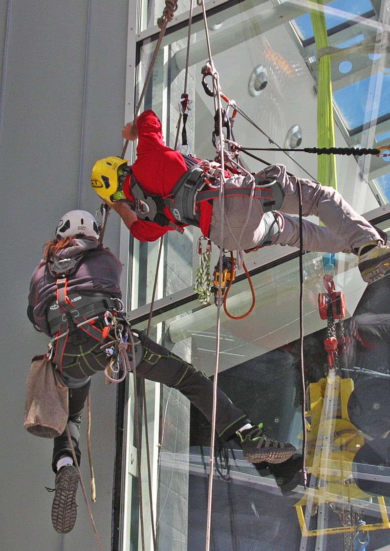
10 4 TYPES OF PPE SYSTEMS SISTEMI DI PROTEZIONE INDIVIDUALE Different PPE devices are assembled together to create systems and subsystems which protect the operator in the event of a fall from a height, preventing or arresting the fall. They can be classified as follows. I dispositivi di protezione individuale contro le cadute dall alto vengono assemblati per creare dei sistemi individuali che proteggono l operatore contro le cadute dall alto, evitandone o arrestandone la caduta libera. Essi si possono classificare come illustrato di seguito. A restraint system limits the movement of the operator so that s/he cannot reach a zone from which a fall from a height is possible. This system does not arrest a fall, rather, it is designed to prevent a fall taking place. Such a system is not suitable for work situations where the operator needs to be supported by a harness. Un sistema di trattenuta limita il movimento dell operatore in modo che questi non possa raggiungere zone dove potrebbe verificarsi una caduta dall alto. Questo sistema non serve ad arrestare una caduta ma è destinato a prevenirla. Non è inoltre adatto a situazioni di lavoro in cui l utilizzatore necessiti di essere sostenuto dall imbracatura. A work positioning system is not for arresting a fall but is used together with an adequate system for arresting a fall. It allows the operator who is in an awkward position to use both hands freely. A positioning device connects the lateral (EN 358) and/or frontal (EN 813) rings of the harness to the anchor points or to the fixed structure. Once it has been adjusted, the operator s weight is comfortably supported. Un sistema di posizionamento sul lavoro non serve ad arrestare una caduta ma va usato in aggiunta ad un adeguato sistema di arresto caduta. Questo sistema è estremamente utile all operatore che si trovi in posizioni scomode e debba lavorare a mani libere. Un dispositivo di posizionamento collega gli anelli laterali (EN 358) e/o ventrale (EN 813) dell imbracatura con l ancoraggio o la struttura. Una volta regolato, sostiene comodamente il peso dell operatore. A fall arrest system arrests the operator s fall, limiting the loading on the body while doing so. This system allows the user to reach zones or positions in which the risk of falling freely exists and, if a fall occurs, limits the length of the fall and arrests the fall. A fall arrest system includes an energy dissipation device to limit loading on the body to tolerable value. Before use, it is necessary to consider the concept of Fall Factor (page 8) and fall clearance distance (page 10). Un sistema di arresto caduta serve ad arrestare la caduta dell operatore e limita la sollecitazione sul corpo dello stesso durante la fase di arresto della caduta. Questo sistema permette all utilizzatore di raggiungere zone o posizioni in cui esiste il rischio di caduta libera e, nel caso in cui questa si verifichi, ne limita la lunghezza fino ad arrestarla. Un sistema di arresto caduta deve inoltre comprendere un sistema di dissipazione dell energia che contenga le sollecitazioni entro dei valori tollerabili dal corpo umano. Prima dell utilizzo è necessario tenere in considerazione i concetti di fattore di caduta (pag. 8) e tirante d aria (pag. 10). S W A rope access system allows the operator to work while suspended, avoiding or arresting a fall. This system is comprised of a working line (W) and a safety line (S), each separately anchored to the structure but both fixed to the operator s harness. The operator can descend down and climb back up the working line or remain suspended in the working position. The safety line is loaded only if there is a problem with the working line or the operator makes a mistake. Un sistema di accesso mediante corda permette all operatore di lavorare in sospensione, evitando o arrestando la caduta libera dello stesso. Questo sistema comprende una linea di lavoro (W) e una linea di sicurezza (S) che sono collegate separatamente alla struttura ma entrambe connesse all imbracatura dell operatore. La linea di lavoro consente all operatore di calarsi e risalire lungo di essa oppure rimanervi sospeso in una posizione di lavoro. La linea di sicurezza entra in trazione solamente nel caso in cui la linea di lavoro abbia un problema o l operatore compia una manovra errata. A rescue system allows an operator to rescue him/herself or other workers. It allows the lifting or lowering of a person to a safe place. Un sistema di salvataggio consente ad un operatore di salvare sé stesso o altri operatori. Esso permette di sollevare o di abbassare la persona soccorsa in un posto sicuro. 8 Not exhaustive information: always consult the user s instructions of each device and the technical manuals. Attention! It is essential to posses a proper technical education! Informazioni non esaurienti: consultare le istruzioni d uso dei singoli dispositivi e i manuali tecnici. Attenzione! Un adeguata formazione tecnica è indispensabile!
11 5 TYPES OF HARNESS TIPOLOGIE DI IMBRACATURE TEMPORARY WORK AT HEIGHT LAVORO TEMPORANEO IN QUOTA 1 The harness restrains the body and must be worn for temporary work at height. It connects the operator to her/his protection system and, in certain cases, it can hold her/him suspended or during the arresting of a fall. They can be classified as illustrated below. L imbracatura è un dispositivo di contenimento per il corpo ed è indispensabile indossarla in qualsiasi lavoro temporaneo in quota. Essa consente il collegamento al proprio sistema di protezione e, in certi casi, lo potrà mantenere in sospensione o arrestarne un eventuale caduta. Essi si possono classificare come illustrato di seguito. FULL BODY HARNESSES IMBRACATURE ANTICADUTA EN 361 POSITIONING HARNESSES IMBRACATURE DI POSIZIONAMENTO EN 358 / EN 813 COMPLETE HARNESSES IMBRACATURE COMPLETE EN 358 / EN 813 / EN 361 EN 361 EN 361 EN 361 EN 361 EN 813 EN 813 EN 358 EN 358 EN 358 EN 358 Equipped with 2 attachment points, one on the sternum and one on the back, to which a fall arrester device can be connected. Presentano due punti di attacco, sternale e dorsale, che sono gli unici a cui possa essere collegato un dispositivo anticaduta. Equipped with one central attachment point EN 813 and two lateral points EN 358. For use only in situations where there is no risk of faling or CPE is present. Presentano un punto di attacco centrale EN 813 e due laterali EN 358. Si possono utilizzare esclusivamente in situazioni dove non esista il pericolo di caduta o siano presenti dei DPC. Complete harnesses (full body + positioning + suspension) have all of the above-mentioned attachment points, suitable for all types of temporary work at height and are the only type to be used during work with ropes. Le imbracature complete (anticaduta + posizionamento + sospensione) presentano tutti i punti di attacco indicate, sono quindi adatte a qualsiasi lavoro temporaneo in quota e sono le uniche da utilizzarsi durante il lavoro in fune. 5.2 / RESCUE HARNESSES. Further to the models above illustrated, there is a special harnesses category intended for rescue, which meets the norms EN EN The evacuation triangle (mod. Rescue Triangle - 7H123) belongs to this group, and its utilization is highlighted during the operations of EVACUATION FROM CABLEWAY INSTALLATIONS. 5.2 / IMBRACATURE DA SALVATAGGIO. Oltre alle tipologie illustrate sopra esiste anche una particolare categoria di imbracature destinate al salvataggio che rispondono alle normative EN EN Appartiene a questa famiglia il triangolo di evacuazione (mod. Rescue Triangle - 7H123) il cui utilizzo è ben evidenziato nell attività di EVACUAZIONE DA IMPIANTI A FUNE. 9
12 6 FALL FACTOR FATTORE DI CADUTA The human body can withstand a loading of up to 6 kn without internal injuries being caused. This value is reached when a 100 kg body is accelerated or decelerated at 6 g (1 g = 9,81 m/s 2 ). A deceleration of 6 g is reached, for example, when a fall of 6 m is braked over a distance of 1 m, and this value is used as the maximum the body can withstand and is used in the relevant legislation. The fall factor is a value which describes how dangerous a fall is and is defined as the height lost in the fall divided by the length of the rope (or safety device) that joins the person to the anchor point: F = H / L F = fall factor; H = height lost in the fall; L = length of the rope or safety device. È stato accertato che la massima sollecitazione che il corpo umano può sopportare senza che si verifichino lesioni interne è di circa 6 kn. Tale valore si raggiunge sottoponendo un corpo di 100 kg ad un accelerazione o decelerazione di 6 g (1 g = 9,81 m/s 2 ). Una decelerazione di 6 g si raggiunge, ad esempio, con 6 m di caduta rallentati in 1 m e tale valore è assunto come limite di sicurezza fisiologico e prescritto dalle normative. Il fattore di caduta è un valore che descrive la pericolosità della caduta ed è definito dal rapporto tra la quota persa nella caduta e la lunghezza della corda (o del dispositivo) che collega la persona con il punto di assicurazione: F = H / L F = fattore di caduta; H = quota persa nella caduta; L = lunghezza della corda o del dispositivo di collegamento. H L Esempio / example: H = 0,3 m L = 1,5 m F = 0,3 / 1,5 = 0,2 The fall factor has a value between 0 and 2, where 2 represents the maximum fall factor value that can be accepted while working at height. Il valore del fattore di caduta deve essere compreso tra 0 e 2, dove 2 rappresenta il fattore di caduta massimo accettabile nell ambito dei lavori in quota. A too-high fall factor can cause high decelerations and lead to: serious injuries to the operator, due to the sharp deceleration to which the body is subjected at the moment of arrest; breakage of or damage to the equipment used, due to the force exerted at the moment of impact. To limit such risks it is vital, in certain situations, to use an energy dissipation system: this allows loading to be kept below the 6 kn level. Devices with an energy dissipation system are classified into 3 classes: guided type fall arresters with cable or rope EN 353; retractable fall arresters EN 360; lanyards with energy absorbers EN 355. Un fattore di caduta troppo elevato può dare origine ad elevate decelerazioni e comportare: ferite gravi dell operatore, dovute alla brusca decelerazione sopportata al momento dell arresto; rottura o danneggiamento dei dispositivi impiegati, dovuti alla forza che agisce su di essi al momento dell impatto. Per contenere questi rischi è indispensabile, in certe situazioni, utilizzare un sistema di dissipazione dell energia: ciò consente di contenere le sollecitazioni entro un limite di 6 kn. I dispositivi dotati di sistemi di dissipazione di energia si dividono in tre categorie: anticaduta su cavo o corda EN 353; anticaduta retrattili EN 360; cordini con assorbitore di energia EN Not exhaustive information: always consult the user s instructions of each device and the technical manuals. Attention! It is essential to posses a proper technical education! Informazioni non esaurienti: consultare le istruzioni d uso dei singoli dispositivi e i manuali tecnici. Attenzione! Un adeguata formazione tecnica è indispensabile!
13 TEMPORARY WORK AT HEIGHT LAVORO TEMPORANEO IN QUOTA 1 EN 355 EN 355 EN 354 OK! EN 354 DANGER F ~ 0 F ~ 1 F ~ 2 F > 1 Optimal situation. The anchor point is above the operator, the system connecting the operator and the anchor point is in tension, and a possible fall is arrested immediately. The use of a fall arrester device is advisable, however it is also possible to employ an EN 354 lanyard made with dynamic rope. These lanyards, only in case of fall factor < 0.5, grant an arresting force < 6 kn during the arresting of the fall. Situazione ottimale. Il punto di ancoraggio si trova sopra all operatore, il sistema di collegamento è in tensione e l arresto di un eventuale caduta è immediato. È consigliabile utilizzare un dispositivo anticaduta, ma, come mostrato in figura, è possibile impiegare un cordino EN 354 realizzato con corda dinamica. Tali cordini, solo con fattore di caduta < 0.5, garantiscono una forza di arresto della caduta < 6 kn. Normal situation The anchor point is at the same height as the chest or dorsal attachment point of the EN 361 harness. The use of a fall arrester device is necessary. In the diagram the operator is using an EN 355 energy-absorbing lanyard, which partially tore apart during the fall, thus reducing the arresting force. Situazione normale. Il punto di ancoraggio si trova all altezza dell attacco sternale o dorsale EN 361 dell imbracatura dell operatore. È necessario utilizzare un dispositivo anticaduta. Nella figura l operatore sta utilizzando un cordino con assorbitore di energia EN 355 che si è lacerato parzialmente durante la caduta, riducendone la forza di arresto. Critical situation The anchor point is level with the operator s feet. The use of a fall arrester device is indispensable. In the diagram the operator is using an EN 355 energyabsorbing lanyard, which totally tore apart during the fall, thus reducing the arresting force. Situazione critica. Il punto di ancoraggio si trova all altezza dei piedi dell operatore. È indispensabile utilizzare un dispositivo anticaduta. Nella figura l operatore sta utilizzando un cordino con assorbitore di energia EN 355 che si è lacerato totalmente durante la caduta, riducendone la forza di arresto. In case of fall factor > 1, the use of a fall arrester device is indispensable. Danger of death! In case of fall without an energydissipation system, the operator may suffer serious injuries, or fall to the ground due to the rupture of the device in use. Con fattore di caduta > 1 è indispensabile utilizzare un dispositivo anticaduta. Pericolo di morte! In caso di caduta senza un sistema di dissipazione dell energia l operatore potrebbe riportare gravi ferite o cadere a terra a causa della rottura del dispositivo impiegato. 11
14 7 FALL CLEARANCE DISTANCE TIRANTE D ARIA The fall clearance distance is the minimum distance between the operator and the ground needed to guarantee the operator s safety in the event of a fall. The value of the fall clearance distance depends on the fall arrester device used and it is calculated as the sum of the following distances: A) Total length of the device used, including connectors and any lanyards or extensible arms; B) Rope or cable that runs through the device or extension of the energy absorber during the arresting of the (this value depends on the particular device used and is specified in the instructions); C) Standard distance between the chest or dorsal attachment point and the operator s feet (= 1,50 m); D) Minimum safety distance between the operator s feet and the ground (= 1 m). Si definisce tirante d aria la distanza minima tra l operatore e il suolo, necessaria a garantirne la sicurezza in caso di caduta. Il valore del tirante d aria dipende dal sistema di arresto caduta impiegato e si calcola, generalmente, sommando i seguenti valori: A) Lunghezza totale del dispositivo impiegato, inclusi connettori ed eventuali cordini o bracci estensibili; B) Scorrimento del dispositivo anticaduta e/o estensione dell assorbitore di energia dopo avere dissipato una caduta (questo valore dipende dal dispositivo usato ed è indicato nelle relative istruzioni d uso); C) Distanza convenzionale tra l attacco sternale o dorsale dell imbracatura e i piedi dell operatore (= 1,50 m); D) Distanza minima di sicurezza tra i piedi dell operatore e il suolo (= 1 m). A Fig. 1 / Energy absorber with integrated lanyard EN 355 Cordino con assorbitore di energia EN 355 E = A (1,1 m) + B (1,6 m) + C (1,5 m) + D (1 m) = 5,2 m Fig. 2 / Guided fall arrester with extension lanyard EN 353 Anticaduta di tipo guidato con estensione in fettuccia EN 353 E = A (0,5 m) + B (1 m) + C (1,5 m) + D (1 m) = 4 m A A B B E A E C C D D Fig. 1 Fig Not exhaustive information: always consult the user s instructions of each device and the technical manuals. Attention! It is essential to posses a proper technical education! Informazioni non esaurienti: consultare le istruzioni d uso dei singoli dispositivi e i manuali tecnici. Attenzione! Un adeguata formazione tecnica è indispensabile!
15 TEMPORARY WORK AT HEIGHT LAVORO TEMPORANEO IN QUOTA / WARNINGS FOR USE. Some operations require the use of an energy-absorber lanyard (ex. assembling and dismantling of scaffoldings). In this case, it is possible to operate with a potential fall factor >1 (Fig, 1). In order to protect the safety of the operator, the utmost attention must be given to the clearance distance value that indicates the minimum distance above the ground or from intermediate obstacles, in which the anchor point of the lanyard must be located. While climbing up the first metres, before reaching the threshold of the clearance distance, the potential fall factor must be 1. This means that the operator must not exceed, with the EN 361 attachment point of the harness, the anchor point of the lanyard. 7.3 / PENDULUM EFFECT. The pendulum or horizontal fall clearance distance is the horizontal distance travelled after a fall when the operator is not directly below the anchor point. This is a potentially dangerous situation because the operator may hit against an obstacle on the fall trajectory (Fig. 3). 7.2 / PRECAUZIONI D USO. Alcune attività richiedono l utilizzo di un cordino con assorbitore di energia (es. montaggio e smontaggio ponteggi) e, in tal caso, è possibile operare con un potenziale fattore di caduta > 1 (Fig. 1). Per preservare l incolumità dell operaratore è necessario porre la massima attenzione al valore del tirante d aria, che indica l altezza minima dal suolo o da eventuali ostacoli intermedi, a cui si dovrà trovare il punto di ancoraggio del cordino. Durante la salita dei primi metri, prima della soglia del tirante d aria, l operatore dovrà obbligatoriamente operare con fattore di caduta 1: l operatore non dovrà quindi superare, con il punto di attacco EN 361 dell imbracatura, il punto di ancoraggio del cordino. 7.3 / EFFETTO PENDOLO. Si definisce effetto pendolo o tirante d aria laterale, lo spostamento laterale che si verifica in seguito ad una caduta laddove l ancoraggio non si trovi sulla verticale dell operatore. Questa è una situazione potenzialmente pericolosa perché può determinare la collisione dell operatore con un ostacolo presente sulla traiettoria di caduta (Fig. 3). Fig.3 13
16 8 TYPES OF ANCHOR POINTS TIPOLOGIE DI ANCORAGGI All systems and PPE s to safeguard against falling from a height need to be connected to secure anchor points. The choice of the type of anchor and its positioning is one of the most difficult aspects of working at height and the operator s safety depends on it. Anchors are generally divided into three types: artificial. There are removable anchors positioned by the operator (webbings, struts, tripods, anchor weights etc.). These anchors must comply with standard EN 795 and, as a consequence, must be able to withstand 12 kn or 18 kn in the case of non-metallic anchors (webbings, ropes etc.). natural. Anchors made out of natural features present at the place of work (trees, rock spikes etc.); structural. Permanent anchors positioned by the operator (expansion bolts, glue-in bolts, etc.) or made using parts of the building or structure where the work is taking place (wooden beams, beams, pillars). 8.2 / CONNECTING TWO ANCHOR POINTS. To use correctly artificial anchors such as expansion or glue-in bolts, you must evaluate carefully the quality of the support in which they are placed (rock, cement, etc) and place preferably two of them. When the anchors are connected, using two webbings, it is important to bear in mind the angle between the webbings where they are joined: the ideal angle is 90, the maximum allowed angle is 120 or 140 in case of rescue. Tutti i sistemi e i dispositivi di protezione individuale contro le cadute dall alto devono essere collegati a dei punti di ancoraggio sicuri. La scelta del tipo di ancoraggio e del suo posizionamento è una delle parti più difficili del lavoro in quota perché da esso deriva la sicurezza dell operatore. Si è soliti identificare tre categorie di ancoraggi: artificiali. Ancoraggi posizionati dall operatore in modo removibile (fettucce, barre controvento, tripodi, corpi morti etc.). Questi ancoraggi devono essere conformi alla norma EN 795 e, come tali, devono essere in grado di sostenere almeno 12 kn oppure 18 kn in caso di ancoraggi non metallici (fettucce, corde etc.). naturali. Ancoraggi creati sfruttando gli elementi naturali presenti sul luogo di lavoro (alberi, spuntoni di roccia etc.); strutturali. Ancoraggi posizionati dall operatore in modo permanente (tasselli ad espansione, fittoni resinati etc.) o creati sfruttando degli elementi facenti parte dell edificio o della struttura dove si svolge il lavoro (travi in legno, putrelle, pilastri). 8.2 / COLLEGAMENTO DI DUE PUNTI DI ANCORAGGIO. Per utilizzare correttamente ancoraggi artificiali come tasselli ad espansione o fittoni resinati è obbligatorio valutare attentamente la qualità del supporto in cui andranno posizionati (roccia, cemento etc.) e collocarne preferibilmente due. Durante la fase di collegamento dei due ancoraggi, che si otterrà con due fettucce, tenere inoltre in considerazione l angolo che si verrà a creare al vertice: l angolo ideale è 90, l angolo massimo consentito è 120 o 140 in caso di soccorso. Fig. 1 Fig. 2 Fig. 3 Esempio / example: 71% 71% 100% 100% The values are expressed in %: having a load of 100 N with an angle of 90, each anchor point supports 71 N (Fig. 1). I valori sono espressi in %: per un carico di 100 N con angolo di 90 ogni ancoraggio sosterrà 71 N (Fig. 1) % % F F F 14 Not exhaustive information: always consult the user s instructions of each device and the technical manuals. Attention! It is essential to posses a proper technical education! Informazioni non esaurienti: consultare le istruzioni d uso dei singoli dispositivi e i manuali tecnici. Attenzione! Un adeguata formazione tecnica è indispensabile!
17 TEMPORARY WORK AT HEIGHT LAVORO TEMPORANEO IN QUOTA / USE OF A WEBBING To use correctly a natural or structural anchor (wooden beam, steel girder, tree, etc.) it is usual to employ a webbing or a webbing with stitched rings at the ends, whose ends should be directly connected with EN 362 connectors, using one such connector for each rope used. If a multi-anchor bolt hanger is used, two EN 362 connectors or one EN 362 high load connector (ex. 50 kn) should be used to connect it to the webbings (Fig. 8). To avoid the webbing slipping around a structural anchor, it can be wrapped twice around the anchor (Fig. 5). Important! Do not use a larksfoot knot since it reduces substantially the strength of the webbing (Fig. 6-7). 8.3 / UTILIZZO DI UNA FETTUCCIA Per utilizzare correttamente un ancoraggio strutturale o naturale (trave di legno, putrella, pianta etc.) si utilizza solitamente un anello di fettuccia o una fettuccia con anelli terminali, le cui estremità devono essere collegate direttamente a dei connettori EN 362, uno per ogni corda impiegata. In caso di utilizzo di una piastra multi-ancoraggio è necessario collegarla alla fettuccia tramite due connettori EN 362 o un connettore EN 362 ad alto carico (es. 50 kn) (Fig. 8). Per evitare lo scorrimento della fettuccia attorno ad un ancoraggio strutturale si può realizzare un doppio giro (Fig. 5). Attenzione! Non creare nodi a bocca di lupo perché la resistenza della fettuccia diminuirebbe notevolmente (Fig. 6-7). Fig. 4 Fig. 5 Fig. 6 Fig. 7 Fig. 8 LEGEND OF TABLES LEGENDA DELLE TABELLE 1 REF. No. 2 MATERIAL 3 SIZES (mm) STANDARDS 8 9 OTHER FEATURES A B ) Reference number / Codice articolo; 2) Material of costruction / Materiale di costruzione; 3) Sizes (lenght-heigh) / Misure (lunghezza - altezza); 4) Maximum gate opening (Ø) / Massima apertura leva (Ø); 5) Weight (g or kg) / Peso (g o kg); 6) Guaranteed breaking strenght (major axis closed gate, minor axis closed gate and major axis open gate) / Carichi di rottura garantiti (asse maggiore leva chiusa, asse minore leva chiusa e asse maggiore leva aperta); 7) Standards reference / Norme di riferimento; 8) EC marking to identify the items conform to the european directive PPE 89/686/CEE and /or number of the production process controlling body / Marchio CE per identificare gli articoli conformi alla direttiva 89/686/ CEE e/o numero dell organismo che interviene nella fase di controllo della produzione; 9) Other features (es. Product under certification; Hot forging (A); U.I.A.A. label (B) etc.) / Altre caratteristiche (es. Prodotti in fase di certificazione; Forgiatura a caldo (A); label U.I.A.A (B) etc); 10) Guaranteed breaking strenght of pulleys / Carichi di rottura garantiti delle carrucole 11) Correct rope and metallic cables diameters / Corretti diametri di cavi metallici e corde 15
18 9 TECHNICAL FEATURES CARATTERISTICHE TECNICHE Aludesign S.A. is certified accordingly to Quality system UNI EN ISO 9001:2008, to which all manufacturing cycles refer to, each product is certified to the relevant CE/EN reference norm and, for additional safety, every product is individually tested or inspected as clearly specified for each item reference. Operational individual inspection - for every CT product; Individual control at 12 kn - for the connectors and all the products bearing this indication. Furthermore: Our internal laboratory carries out more than destruction tests per year (one complete test every 6 minutes). We have set up automatic machine for testing the life-span of the connector s gates. The life-span is calculated as the number of cycles (opening and closing the gate) achieved without having a noticeable decrease in performance. Our karabiners exceed cycles, without a consistent impairment. Oltre alla certificazione con il sistema di qualità ISO 9001:2008, al quale fanno riferimento tutti i processi produttivi, e ai controlli eseguiti in ottemperanza delle norme CE/EN di riferimento, abbiamo istituito il controllo individuale del prodotto grazie al quale nessun prodotto potrà raggiungere il cliente senza essere stato individualmente testato: Controllo individuale funzionale - per qualsiasi prodotto CT; Controllo individuale a 12 kn - per i connettori e tutti i prodotti che riportino questa indicazione. Inoltre: Il nostro laboratorio interno esegue più di test distruttivi ogni anno (una trazionatura ogni 6 minuti circa). Abbiamo realizzato un macchinario per testare la durata delle leve dei connettori. La durata espressa in N di cicli (apertura e chiusura) supera i cicli senza compromissioni a livello funzionale. 9A GATE LOCKING SYSTEM TYPOLOGY TIPOLOGIE DI BLOCCAGGIO LEVA SCREW GATE (SG) GHIERA A VITE (SG) Two movements are necessary to open the gate (1 - unscrew, 2 - open). Attention! It s necessary to screw in order to guarantee lock the gate. Sono necessari due movimenti per aprire la leva (1 - svitare, 2 - aprire). Attenzione! È necessario riavvitare per garantire la chiusura della leva. TWIST-LOCK GATE (WG) GHIERA TWIST-LOCK (WG) Two movements are necessary to open the gate (1 - twist, 2 - open). Attention! It automatically comes back in the locking position of the gate. Sono necessari due movimenti per aprire la leva (1 - ruotare, 2 - aprire). Attenzione! La leva ritorna automaticamente in posizione di bloccaggio. TRIPLEX GATE (TG) GHIERA TRIPLEX (TG) Three movements are necessary to open the gate (1 - push, 2 - twist, 3 - open). Attention! It automatically comes back in the locking position of the gate. Sono necessari tre movimenti per aprire la leva (1 - spingere, 2 - ruotare, 3 - aprire). Attenzione! La leva ritorna automaticamente in posizione di bloccaggio DOUBLE GATE DOPPIA LEVA Two movements are necessary to open the gate (1 - push, 2 - open). Attention! It automatically comes back in the locking position of the gate. Sono necessari due movimenti per aprire la leva (1 - spingere, 2 - aprire). Attenzione! La leva ritorna automaticamente in posizione di bloccaggio. AUTOMATIC GATE GHIERA AUTOMATICA Two movements are necessary to open the gate (1 - push, 2 - open). Attention! It automatically comes back in the locking position of the gate. Sono necessari due movimenti per aprire la leva (1 - spingere, 2 - aprire). Attenzione! La leva ritorna automaticamente in posizione di bloccaggio. ALL THE CONNECTORS ARE INDIVIDUALLY TESTED AT 12 kn. TUTTI I MOSCHETTONI SONO INDIVIDUALMENTE TESTATI A 12 kn. 16 Not exhaustive information: always consult the user s instructions of each device and the technical manuals. Attention! It is essential to posses a proper technical education! Informazioni non esaurienti: consultare le istruzioni d uso dei singoli dispositivi e i manuali tecnici. Attenzione! Un adeguata formazione tecnica è indispensabile!
19 TECHNICAL FEATURES AND SYMBOLS CARATTERISTICHE TECNICHE E SIMBOLI 1 9B SPECIAL FEATURES CARATTERISTICHE SPECIALI ACL SYSTEM (ANTI CROSS LOADING) SISTEMA ACL (ANTI CROSS LOADING) The ACL system allows to maintain stable eyelet ropes or webbings inserted in the connector. It allows an easy positioning or removal. It avoids the danger to load along minor axis. Il sistema ACL permette di mantenere stabile la corda asolata o la fettuccia inserite nel connettore, consentendone un facile posizionamento o rimozione. Previene il pericolo di carico lungo l asse minore. CAPTIVE BAR BARRETTA CAPACITIVA The captive bar could be supplied assembled or loose, to be assembled by the customer. La barretta capacitiva può essere fornita montata oppure sciolta da montare da parte del cliente. 3 kn FALL INDICATOR INDICATORE DI CARICO 3 kn The swivel with F.I. activation, assembled on connectors, lifts and covers the green ring once the 3 kn (~ 300 Kg) load is over. This way, after any fall, it is possible to replace the connector and to revise. Il girello con indicatore di carico, montato sui connettori, si solleva e copre l anello verde una volta superati i 3 kn (~ 300 Kg). In questo modo, dopo qualsiasi caduta, è possibile procedere alla sostituzione del connettore e alla revisione del sistema. 9C LOCKING SYSTEM SISTEMI DI CHIUSURA TRADITIONAL LOCKING SYSTEM CHIUSURA TRADIZIONALE This locking system is recommended in dirty environnements, where it s necessary to clean the carabiner easily. Sistema di chiusura consigliato per ambienti sporchi, dove è necessario pulire facilmente il moschettone. CATCH FREE LOCKING SYSTEM CHIUSURA CATCH FREE This locking system makes the hooking and releasing movements of the carabiners more fluent, avoiding the catching in ropes, webbings and anchoring points. Sistema di chiusura che rende più fluidi i movimenti di aggancio e sgancio del moschettone senza possibilità di impigliarsi in corde, fettucce o ancoraggi. Note: the abbreviation that follows the name of the carabiner, indicates the type of gate. Besides, the final letter L indicates that the connector is equipped with ACL system: Concept SG = screw gate version; Concept SGL = screw gate version with ACL system; Concept TGL = triplex gate version with ACL system. Nota: l abbreviazione che segue il nome del moschettone, ne indica la tipologia di leva. La lettera finale L indica, inoltre, che il connettore è dotato di sistema ACL: Concept SG = versione con ghiera a vite; Concept SGL = versione con ghiera a vite e sistema ACL; Concept TGL = versione con ghiera triplex e sistema ACL 17
20 EN 353-1:2014 EN 353-2:2002 AISI 304 MADE IN ITALY Patented PATENTS BREVETTI Aludesign S.A. has registered over 20 world-wide patents. We have introduced in the market devices that have stated new safety standards. These products are still a benchmark reference. Aludesign S.A. ha realizzato oltre 20 brevetti depositati a livello internazionale e introdotto sul mercato dispositivi che dettano nuovi standard di sicurezza. Questi prodotti rappresentano ancora oggi un punto di riferimento tecnico a livello mondiale. DOWN RAPID RELEASING SYSTEM FOR ASCENDERS DISPOSITIVO DI SBLOCCO RAPIDO PER RISALITORI Thanks to the double pivot, it is possible to quickly release the cam, pushing on the relevant gate. Doing so, it is possible to go down easily for short stretches. Grazie all azione del doppio perno, è possibile sbloccare in modo rapido la camma premendo sull apposita leva. In questo modo si possono effettuare brevi tratti in discesa senza fatica. COMBINED ANCHOR AND PULLEY FOR EVACUATION FROM CABLE CARS AND CHAIR LIFT CARRUCOLA / ANCORAGGIO PER L EVACUAZIONE DEGLI IMPIANTI A FUNE Easy Rescue device allows evacuation by allowing rescuers to be lowered along the cable, or when the underlying terrain permits it, to allow the unloaded pulley to run down the cable to the desired position and then use it as a winch and lower anchor. Il dispositivo Easy Rescue consente di effettuare l evacuazione facendo scorrere i soccorritori lungo la fune metallica, oppure ove il terreno sottostante lo consenta, far scorrere la carrucola scarica sino alla posizione voluta, per poi utilizzarla come ancoraggio di recupero e di calata. R 1 UP ALTO HAUT AUF 2 SKC EVO QUICK TREE REMOVABLE FOOT ROPE CLAMP BLOCCANTE DA PIEDE REMOVIBILE QUICK TREE Rope clamp for right or left foot designed for tree climbing. The device can be used on two different supports: QT Universal, this support can be installed onto any boot by using the webbing system with the adjustment buckle; QT Spurs, this support has been designed to be installed onto any tree climbing crampons. Bloccante da piede destro o sinistro progettato per il tree climbing. Il dispositivo può essere applicato su due differenti supporti: QT Universal, supporto di fissaggio installabile su qualsiasi scarpone mediante un sistema di fettucce con fibbia di regolazione; QT Spurs, supporto di fissaggio progettato per essere installato su qualsiasi rampone da tree climbing. OPENING SYSTEM OF SKC EVO FALL ARRESTER SISTEMA DI APERTURA ANTICADUTA SKC-EVO Innovative double action opening system: to open the device, first of all you must press the safety lever (1) and then push the locking lever (2) upwards. The device can only be opened if the action is carried out in the sequential way to therefore eliminate the risk of accidental opening. Innovativo sistema di apertura double action: per aprire il dispositivo è necessario dapprima premere la levetta di sicurezza (1) e successivamente spingere verso l alto la leva di bloccaggio (2). Il dispositivo si apre solo se l azione è svolta in modo sequenziale eliminando così il pericolo di un apertura accidentale. 18 Not exhaustive information: always consult the user s instructions of each device and the technical manuals. Attention! It is essential to posses a proper technical education! Informazioni non esaurienti: consultare le istruzioni d uso dei singoli dispositivi e i manuali tecnici. Attenzione! Un adeguata formazione tecnica è indispensabile!
21 PATENTS AND STANDARDS BREVETTI E NORMATIVE 1 STANDARDS NORMATIVE TECHNICAL NORM OF REFERENCE: EN 363 / Personal fall protection systems. PPE for preventing a fall from a height. EN 354 / Lanyards and swivels. EN 358 / Belts for work positioning and restraint and work positioning lanyards. PPE for minimizing the consequences of a fall from a height. EN / Guided type fall arresters including a rigid line anchor. EN / Guided type fall arresters including a flexible line anchor. EN 355 / Energy absorbers. Lanyards with energy absorbers. EN 360 / Retractable type fall arresters. EN 361 / Full body anti fall harnesses. EN 362 / Connectors. Classes: B - Basic connectors. M - Multipurpose connectors. T - Terminal connectors. A - Anchorage connectors. Q - Quick link. PPE for evacuation, rescue, vertical positioning. EN 1496 / Rescue lifting devices. EN 1497 / Rescue harnesses. EN 1498 / Rescue loops. EN / Rope access systems. A) Safety line adjustment device. B) Working line ascender. C) Working line descender. PPE for mountaineering EN / Connectors for mountaineering and multi-anchor plates. EN / Harnesses. EN / Pulleys. EN / Helmets for mountaineering. EN 566 / Quick-draws, slings and rings. EN 567 / Ascenders. Other norms of reference: EN 341 / Descender devices for rescue: type 1 - automatic descender device; type 2 - manually-operated descender device. Classes: A) Descent energy W up to 7, J (ex. 75 kg x 100 m x 100 descents); B) Descent energy W up to 1, J (ex. 75 kg x 100 m x 20 descents); C) Descent energy W up to 0, J (ex. 75 kg x 33 m x 20 descents); D) For only one descent. EN 397 / Industrial safety helmets. EN 1891 / Low stretch kernmantel ropes: A - Work support and back-up safety rope (superior performance); B - Work and hauling rope (inferior performance). EN 395 / General requirements for instructions of use and marking. EN 517 / Prefabricate accessories for roofing. Roof safety hooks. EN 813 / Sit harnesses rescue harness. EN 795 / Removable anchor devices for single user. Types: A) Anchor device with the need for a structural anchor or fixing element; B) Anchor device without the need for a structural anchor or fixing element; C) Anchor device employing a flexible anchor line which deviates from the horizontal by not more than 15 ; D) Anchor device employing a rigid anchor line which deviates from the horizontal by not more than 15 ; E) Anchor devices for use on surfaces up to 5 from the horizontal where the performance relies solely on the mass and the friction between itself and the surface. NORMA TECNICA DI RIFERIMENTO: EN 363 / Sistemi di protezione individuale contro le cadute dall alto. DPI atti a prevenire il rischio di caduta EN 354 / Cordini di trattenimento, girello. EN 358 / Cinture di posizionamento sul lavoro e di trattenuta e cordini di posizionamento sul lavoro. DPI per l arresto della caduta EN / Dispositivi anticaduta di tipo guidato su una linea di ancoraggio rigida. EN / Dispositivi anticaduta di tipo guidato su una linea di ancoraggio flessibile. EN 355 / Assorbitori di energia. Cordini muniti di assorbitore di energia. EN 360 / Dispositivi anticaduta di tipo retrattile. EN 361 / Dispositivi imbracature Anticaduta per il corpo. EN 362 / Connettori. Classi: B - Connettore di base. M - Connettore multiuso. T - Connettore terminale. A - Connettore designato per un ancoraggio specifico. Q - Connettore per connessioni semi-permanenti. DPI per l evacuazione, il soccorso, la discesa su corda. EN 1496 Dispositivo di sollevamento soccorso. EN 1497 Imbracatura di salvataggio. EN 1498 Cinghiaggi di salvataggio. EN Sistemi di accesso su fune. A) Dispositivo di regolazione della linea di sicurezza. B) Risalitore della linea di lavoro. C) Discensore della linea di lavoro. DPI per l alpinismo EN / Connettori da alpinismo e piastre multiancoraggio. EN / Imbracature. EN / Carrucole. EN / Caschi per alpinismo. EN 566 / Rinvii e anelli di fettuccia EN 567 / Bloccanti risalitori. Altre norme di riferimento: EN 341 / Dispositivi di discesa per salvataggio: tipo 1 - discensore automatico; tipo 2 - discensore a controllo manuale. Classi: A) Energia di discesa W fino a 7, J (es. 75 kg x 100 m x 100 discese); B) Energia di discesa W fino a 1, J (es. 75 kg x 100 m x 20 discese); C) Energia di discesa W fino a 0, J (es. 75 kg x 33 m x 20 discese); D) Per una sola discesa. EN 397 / Elmetti di protezione per l industria. EN 1891 / Corde statiche con guaina a basso coefficiente di allungamento: A - Corda di lavoro e di sicurezza (prestazioni superiori); B - Corda di lavoro e sollevamento (prestazioni inferiori). EN 365 / Requisiti generali per le istruzioni d uso e la marcatura. EN 517 / Accessori prefabbricati per coperture. Ganci di sicurezza da tetto. EN 813 / Cinture con cosciali. EN 795 / Dispositivi di ancoraggio removibili per utilizzatore singolo. Tipo: A) Dispositivi di ancoraggio che necessitano di un ancoraggio strutturale (es. piastrine); B) Dispositivi di ancoraggio che non necessitano di un ancoraggio strutturale (es. fettucce); C) Dispositivi di ancoraggio per linee di ancoraggio flessibili con inclinazione massima di 15 rispetto all orizzontale; D) Dispositivi di ancoraggio per linee di ancoraggio rigide con inclinazione massima di 15 rispetto all orizzontale; E) Dispositivi di ancoraggio a corpo morto per superfici con inclinazione massima di 5 rispetto all orizzontale. 19
22 PPE INSPECTION CONTROLLO DEI DPI Carrying out regular periodic checks (at intervals predetermined by the manufacturer) is vital for ensuring the equipment s efficiency and durability and the user s safety. The implementation of regular periodic checks is defined in the standard EN 365 and is therefore only mandatory for some categories of devices in which the requirement will be specifically indicated in the instructions for use. Carrying out periodical controls doesn t relieve the user nor from the obligation to perform the controls before and after each use, neither to require an extraordinary periodic check, in case an outstanding event occurs (ex. a fall, even from a low height, a change of user etc.), or in case of doubts about the correct functioning of the device. Attention! The examiner, after carrying out the periodical check, has the responsibility of the good functioning of a PPE. The check must be performed with the highest accuracy, without haste and after completing all the necessary steps. The regular periodic checks must be carried out: at least every 12 months, with normal/standard use; at least every 6 months in the case of intense use or in aggressive environments (ex. marine environment); in case an anomaly has been found during the checks before and after each use; every time there is a change of user; filling in the sheet for the periodic check included in the manual. The check can be carried out: by Aludesign S.A.; by a competent person authorised by Aludesign S.A. For more detailed information about the courses contact the following addresses: for Italy > vendite@aludesign.it for overseas > commerciale@aludesign.it The sheet for the periodic check must be completed: following the instructions as described in the specific checking of each device (check for latest updates on the website ppe.climbingtechnology.com); consulting the photographs at the end of each sheet; consulting the instructions for using the device, if necessary downloading them from: examining the device in a suitable well-lit and tidy worksho The annual sheet for the periodic check is composed by a check list where the output of the inspection must be indicated, for each stage. On completion of the verification procedure, the device may be declared: FIT FOR USE, UNFIT FOR USE or TO BE CHECKED/ TO KEEP CONTROLLED. Note. A device that is TO BE CHECKED/ TO KEEP CONTROLLED is a device that presents minor defects to pay attention to during inspections before and after use and because of this the periodic inspection can be anticipated as opposed to the 12 or 6 month period foreseen. L esecuzione dei controlli periodici regolari (ad intervalli prestabiliti dal costruttore) è indispensabile per garantire la continua efficienza e durabilità del dispositivo, da cui dipende la sicurezza stessa dell utilizzatore. L esecuzione dei controlli periodici regolari è prevista dalla norma EN 365 ed è quindi obbligatoria solo per alcune categorie di dispositivi nelle cui istruzioni d uso tale obbligo sarà espressamente indicato. L esecuzione dei controlli periodici non esime l utilizzatore dall obbligo di effettuare i controlli prima e dopo ogni utilizzo, né di richiedere un controllo periodico straordinario al verificarsi di eventi eccezionali (es. una caduta anche da altezza contenuta, un cambio di utilizzatore etc.) o in caso di dubbi sul buon funzionamento del dispositivo. Attenzione! Il revisore, dopo averne effettuato il controllo periodico, è responsabile del buon funzionamento di un DPI. Il controllo deve essere effettuato con la massima serietà, senza fretta e senza saltare alcun passaggio. Il controllo periodico di un dispositivo deve essere effettuato: almeno ogni 12 mesi, in caso di utilizzo normale; almeno ogni 6 mesi in caso di utilizzo intenso o in ambienti aggressivi (es. ambiente marino); in presenza di anomalie riscontrate durante i controlli prima e dopo ogni utilizzo; ogniqualvolta ci sia un cambio di utilizzatore; compilando la scheda per il controllo periodico generale inclusa nel manuale. Il controllo può essere effettuato: da Aludesign S.A.; da una persona competente autorizzata da Aludesign S.A. Per maggiori informazioni riguardo i corsi contattate i seguenti indirizzi: per l Italia > vendite@aludesign.it per l estero > commerciale@aludesign.it La scheda di controllo periodico deve essere compilata: seguendo le istruzioni specifiche di ogni singolo dispositivo (verificarne l ultimo aggiornamento al sito ppe.climbingtechnology. com); consultando il materiale fotografico in coda a ciascuna scheda; consultando le istruzioni d uso del dispositivo, oppure scaricandole dal sito: esaminando il dispositivo in ambiente idoneo, ordinato e ben illuminato. La scheda annuale di controllo periodico è composta da una check list dove va indicato, per ciascun punto, l esito del controllo. Al termine della procedura di controllo il dispositivo potrà essere dichiarato: IDONEO ALL USO, NON IDONEO ALL USO o DA VERIFICARE/TENERE CONTROLLATO. Nota. Un dispositivo DA VERIFICARE/TENERE CONTROLLATO è un dispositivo che presenta difetti lievi a cui prestare attenzione durante i controlli prima e dopo l uso e per cui il controllo periodico successivo può essere anticipato rispetto ai 12 o 6 mesi previsti. For more information visit the site: Per maggiori informazioni consultare il sito: 20 Not exhaustive information: always consult the user s instructions of each device and the technical manuals. Attention! It is essential to posses a proper technical education! Informazioni non esaurienti: consultare le istruzioni d uso dei singoli dispositivi e i manuali tecnici. Attenzione! Un adeguata formazione tecnica è indispensabile!
23 PPE INSPECTION CONTROLLO DEI DPI 1 PERIODIC CHECKING OF PERSONAL PROTECTIVE EQUIPMENT WORK POSITIONING LANYARDS DEVICE IDENTIFICATION SHEET PERIODIC CHECKING OF PERSONAL PROTECTIVE EQUIPMENT WORK POSITIONING LANYARDS Trademark Manufacturer Aludesign S.A. Via Torchio 22, Cisano B.sco (BG) ITALY Product (type, model, code) Serial number Year of manufacture Purchase date / / Data of first use / / Expiry date / / 2.4 CHECK THE REGULATOR S CONNECTOR Reference standards O EN 358 User (company, name and address) PPE included, if present (ex. system composed by more than a PPE) Check that the EN 362 oval connector with the correct serial number is present. If a different connector from the original one is present, replace it with a correct EN 362 oval connector whose serial number should be noted on the inspection sheet in the space for notes. Check the condition of the connector following the inspection procedure and the instructions. 3) FUNCTIONAL CHECK PARTS IDENTIFICATION PRIMARY ELEMENTS Body, side plates, regulator cam and screws, rope and terminations, connector. SECONDARY ELEMENTS / REPLACEABLE PARTS Rope, rope protector sheath, connector. DEVICE PERIODIC CHECK SHEET 3.1 CHECKING THE ROPE RUNS FREELY Attach the regulator s connector to the harness s stomach loop and the end connector to an anchor point. Check that the cord runs freely by pulling it at the talurit end. 3.2 CHECKING THE LOCKING FUNCTIONALITY Check the system locks by loading it with your own weight: the rope must not move. The release of the rope is only possible by manually operating the device as described in the instructions. 1) HISTORY AND GENERAL CHECK 1.1 Check the existence and the readability of the marking details, in particular the CE symbol and the applicable EN norm/standard. 1.2 Check that device has not exceeded the storage and/or in-use lifetime. 3.3 CHECKING THE RELEASE OF THE ROPE With one hand, hold the regulator and rotate it gently. With the other hold the free end of the rope and verify that it can be gradually feeds through the regulator. The examiner s verdict on the severity of the anomaly must be based on objective criteria and the specific training received. The producer accepts no responsibility deriving from inexact information recorded by the user or servicer. 1.3 Check that the device is intact and no parts are missing (check against a new product). 1.4 Check that the device has not been modified outside the factory or serviced in a non-approved centre. 1.5 Check that the device has not experienced an exceptional event (e.g. fall from height, violent blow, etc.). Even in the absence of visible defects or deterioration, the original strength could be seriously reduced. DEVICE TO BE CHECKED / CHECK RESULTS DEVICE FIT FOR USE DEVICE UNFIT FOR USE TO KEEP CONTROLLED Date of the check / / Reason for the check Periodic check Additional check 2) VISUAL CHECK 2.1 CHECKING THE REGULATOR Notes (defects found, repairs SIDE PLATES - Make sure the side plate is not bent and that there are no cuts, cracks or wear, performed or other relevant paying special attention to the areas where the rope and connector touch the side plates. Make information) sure there is no oxidation or corrosion. CAM - Make sure the cam is not bent and that there are no cuts, cracks or wear, paying special attention to the areas where the rope touches the cam. Make sure there is no oxidation or corrosion. SCREWS - Check the condition of the screws and that there is no play between the side plates. Name and signature of the person responsible for checking NAME SIGNATURE PRO23-7L915CTEN_rev.4 Date of next check 67 / / Fill-out this inspection sheet following the inspection procedure, photographs and instructions supplied by the manufacturer, which you can download from com. The examiner s verdict on the severity of the anomaly must be based on objective criteria and the specific training received. The producer accepts no responsibility deriving from inexact information recorded by the user or servicer. PRO23-7L915CTEN_rev Sample pages taken from an inspection sheet. Pagine di esempio estratte da una scheda di ispezione. PHOTO APPENDIX WORK POSITIONING LANYARDS Notes: PHOTO APPENDIX WORK POSITIONING LANYARDS Notes: Rope worn. Rope with damaged sheath: the rope s core can be seen Notes: Rope core protruding. Clear burning on protection sheath. Important! Check the entire length of the rope: the damage on the sheath could be present on the rope as well Notes: Notes: Damaged rope. Note the difference in curvature between the undamaged portion (constant curvature, below left) and the damaged portion (uneven curvature, above right). Rope with damaged core. This damage is best found by feeling the rope, although you can see a slight narrowing of the rope. Clear burning on protection sheath. Important! Check the entire length of the rope: the damage on the sheath could be present on the rope as well. Rope very dirty with deposits of foreign substance Notes: Regulator s cam very worn: see the difference between a new device (right) and one with a worn cam (left). Termination loop damaged: thimble eye and heatshrunk coating partially missing, stitching and rope worn and label illegible Notes: Regulator with cam jammed due to build-up of foreign matter. Regulator s connector and rope protection sheath missing. If there are no other defects, replace missing parts with designated spare parts Regulator with loose screw. Apply low-strength thread-locking fluid and retighten until tight. Regulator with missing screw. Replace with designated spare part. Apply lowstrength thread-locking fluid and retighten until tight. 70 PRO23-7L915CTEN_rev PRO23-7L915CTEN_rev Sample pages taken from a photographic appendix. Pagine di esempio estratte da un appendice fotografica. 21
24 TYPES OF ACTIVITIES WHEN WORKING AT HEIGHT TIPOLOGIA DI ATTIVITÀ LAVORATIVE IN QUOTA In the following pages the principal types of working at height activities are described, with use of the appropriate techniques and Climbing Technology products. Attention! The suggested models are just a selection of those that could be used in a specific contest: for a more complete overview please consult the catalogue section reserved to the products, which shows all the relevant variants. Here below you can find the list of the described activities and of the PPE systems that are used in each of them. Nelle pagine seguenti sono rappresentate le principali attività lavorative in quota, le relative tecniche e i prodotti Climbing Technology utilizzabili in ogni particolare contesto. Attenzione! I modelli suggeriti sono solo una selezione di quelli che potrebbero essere impiegati in un determinato contesto: per una migliore panoramica consultare la parte del catalogo riservata ai prodotti e contenente tutte le relative varianti. Di seguito l elenco delle attività descritte e dei sistemi di protezione individuale utilizzati in ognuna. A WORKING ON A HORIZONTAL SURFACE LAVORO SU PIANO ORIZZONTALE B WORKING ON A ROOF LAVORO SU TETTO C WORKING FROM AN AERIAL PLATFORM LAVORO SU PIATTAFORMA AEREA D WORKING ON A LADDER LAVORO SU SCALA E WORKING ON A PYLON LAVORO SU TRALICCIO F BUILDING AND DISMANTLING SCAFFOLDS MONTAGGIO E SMONTAGGIO PONTEGGI G USE OF RESCUE KITS USO DEI KIT DA SOCCORSO H ROPE ACCESS WORK LAVORO IN SOSPENSIONE SU FUNE S W I WORKING IN CONFINED SPACES LAVORO IN SPAZI CONFINATI L EVACUATION FROM SKI LIFTS EVACUAZIONE DA IMPIANTI A FUNE M TREE CLIMBING LAVORO SU PIANTA S W 22 Not exhaustive information: always consult the user s instructions of each device and the technical manuals. Attention! It is essential to posses a proper technical education! Informazioni non esaurienti: consultare le istruzioni d uso dei singoli dispositivi e i manuali tecnici. Attenzione! Un adeguata formazione tecnica è indispensabile!
25 A WORKING ON A HORIZONTAL SURFACE LAVORO SU PIANI ORIZZONTALI WORKING ON A HORIZONTAL SURFACE LAVORO SU PIANI ORIZZONTALI 1 Whenever the operator must work on a horizontal surface onto which there is the possibility of falling and there is no Collective Protection Equipment, a safe anchor point (A) must be placed to which the operator can be connected through a restraint system. The system allows the operator to move by her/himself only over the safe area of the horizontal surface and will safely prevent a fall. The following PPE must be used while working on the horizontal floor: an EN 397 helmet (1) and an EN 361 full body harness (2) or an EN 358 (3) waistbelt; an EN 354 restraint lanyard (4) or an adjustable EN 358 positioning lanyard (6). The length of lanyard must be appropriate for the safe working area. Qualora l operatore debba lavorare su un piano orizzontale dove ci sia possibilità di caduta e privo di protezioni collettive, dovrà individuare o posizionare un punto di ancoraggio sicuro (A) a cui collegarsi mediante un sistema di trattenuta. Questo sistema consentirà all operatore di muoversi e operare solo in un area sicura del piano orizzontale e ne impedirà la caduta. Nel lavoro su piano orizzontale si dovranno utilizzare i seguenti DPI: un casco EN 397 (1) e un imbracatura anticaduta EN 361 (2) o una cintura EN 358 (3); un cordino di trattenuta EN 354 (4) o un cordino di posizionamento regolabile EN 358 (6). Il cordino impiegato dovrà essere di lunghezza adeguata all area sicura di lavoro. A SAFE WORKING AREA AEREA SICURA 1 / X-WORK 74 2 / WORK TEC 64 3 / WAIST TEC 65 4 / LANYARD 81 5 / CONNECTORS / FINCH 80 23
26 B WORKING ON A ROOF LAVORO SU TETTO Working on a roof means on a roof whose slope is less than 30 (Fig. 1) where the operator, to be able to work safely, has to connect him or herself to a horizontal flexible lifeline which has previously been installed on the apex of the roof (A). If such a lifeline is not already present, a temporary lifeline must be installed by a suitably-qualified worker to allow the work to be carried out in safety. Access to the roof is mainly: from below, using a ladder leaning against the wall of the building; from inside, through a suitable trapdoor (Fig. 3). In both these situations the operator must be correctly secured: in the absence of a lifeline, creating anchor points to reach the apex of the roof (e.g. use of a natural anchor, Fig. 2); with a lifeline, following the procedure in the instruction manual to reach the lifeline. Normally a pre-installed lifeline is reachable using a series of anchor points present on the sloping roof to which the operator connects her or himself with a Y-form lanyard with energy absorber (9), connected correctly to the chest or dorsal attachment ring of the EN 361 harness. Once the lifeline has been reached, three types of protection device can be used: B1) EN 360 retractable type fall arrester (3) of adequate length for the roof connected to the chest or dorsal attachment ring of the EN 361 harness (2); B2/B3) EN 358 adjustable work positioning lanyard (6/8) whose length is adequate for the roof, connected to the chest loop of the EN 813 harness (7). Important! In the above indicated situations, the edges of the roof must be fitted with Collective Protection (B). Attention! When working on a roof it is mandatory to have an emergency kit (10) to be able to rapidly rescue an operator in difficulty, particularly if the person is suspended unconscious. The length of the rope included in the kit must be commensurate with the height of the work site. Il lavoro su tetto si riferisce esclusivamente a coperture con inclinazione inferiore a 30 (Fig. 1) dove l operatore, per lavorare in sicurezza, dovrà collegarsi ad una linea vita orizzontale flessibile già installata sulla linea di colmo (A). Qualora questa non sia presente, un operatore con la dovuta qualificazione dovrà installare una linea vita temporanea tramite la quale poter effettuare il lavoro in sicurezza. L accesso al tetto potrà avvenire: dal basso, utilizzando una scala appoggiata alla parete della casa; dall interno, utilizzando l apposita botola (Fig. 3). In entrambe le situazioni l operatore dovrà essersi assicurato: con linea vita assente, creando dei punti di ancoraggio per raggiungere la linea di colmo (es. uso di un ancoraggio naturale, Fig. 2); con linea vita presente, consultando il relativo manuale d istruzioni dove sarà evidenziata la procedura per raggiungerla. Normalmente una linea vita installata è raggiungibile tramite una serie di ancoraggi presenti sulla falda a cui l operatore si dovrà collegare per mezzo di un cordino a Y con assorbitore di energia (9), collegato correttamente all anello sternale o dorsale EN 361 dell imbracatura. Una volta raggiunta la linea vita potrà utilizzare tre tipologie di dispositivi: B1) anticaduta retrattile EN 360 (3) collegato all anello sternale o dorsale EN 361 dell imbracatura anticaduta (2) di lunghezza adeguata alla falda; B2/B3) cordino di posizionamento regolabile EN 358 (6/8), collegato all anello ventrale EN 813 dell imbracatura (7), di lunghezza adeguata alla falda. Attenzione! Nelle situazioni sopra indicate i bordi del tetto dovranno essere equipaggiati con protezioni collettive (B). Attenzione! Nel lavoro su tetto è obbligatoria la presenza di un kit di emergenza (10) per il soccorso tempestivo di un operatore in difficoltà, specialmente in caso di sospensione inerte. La lunghezza della corda inclusa nel kit dovrà essere adeguata all altezza del sito di lavoro. 1 / WORK-SHELL 72 2 / WORK TEC 63 3 / SERIES / CONNECTORS / EYELET ROPE / EASY MOVE 84 7 / PYL TEC / FINCH 80 9 / FLEX ABS / RESCUE KIT 200R / DUETTO Not exhaustive information: always consult the user s instructions of each device and the technical manuals. Attention! It is essential to posses a proper technical education! Informazioni non esaurienti: consultare le istruzioni d uso dei singoli dispositivi e i manuali tecnici. Attenzione! Un adeguata formazione tecnica è indispensabile!
27 WORKING ON A ROOF LAVORO SU TETTO 1 A A <30 Fig. 1 Fig. 2 Fig. 3 Fig. 4 In case of an inclined slope > 30, we use the technique of work in suspension with rope. Oltre i 30 di inclinazione si utilizza la tecnica di lavoro in sospensione su fune. Use of an opposite anchor point, in order to reach the ridge line, in case the life line is missing. Utilizzo di un ancoraggio opposto, per raggiungere la linea di colmo in caso di linea vita assente. At the exit from the trap door, the anchor points on the pitch allow to reach the life line. Uscendo dalla botola, gli ancoraggi sulla falda permettono di raggiungere la linea vita. The highlighted areas are only reachable using a supplementary belaying. Le aree evidenziate sono raggiungibili solo con un assicurazione supplementare. B1 RETRACTABLE FALL ARRESTER ANTICADUTA RETRATTILE B 11 A B2 ADJUSTABLE WORK POSITIONING LANYARD CORDINO DI POSIZIONAMENTO REGOLABILE B A
28 B3 ADJUSTABLE WORK POSITIONING LANYARD CORDINO DI POSIZIONAMENTO REGOLABILE B 1 A Not exhaustive information: always consult the user s instructions of each device and the technical manuals. Attention! It is essential to posses a proper technical education! Informazioni non esaurienti: consultare le istruzioni d uso dei singoli dispositivi e i manuali tecnici. Attenzione! Un adeguata formazione tecnica è indispensabile!
29 C WORKING FROM AN AERIAL PLATFORM LAVORO SU PIATTAFORMA AEREA WORKING ON A AERIAL PLATFORM LAVORO SU PIATTAFORMA AEREA 1 When using an aerial platform the worker must use: an EN 397 helmet (1); an EN 361 harness (2); a connecting lanyard to join the harness to the designated anchor points (A) on the platform. This prevents the operator from being thrown off the platform, in case of sudden oscillations. The connecting lanyards can be: EN 358 adjustable work positioning lanyard (3), of adequate maximum length and appropriately tightened, attached to the chest or back ring of the EN 361 harness. energy-absorbing lanyard EN 355 attached to the EN 361 chest or back ring of the harness. This solution is used when it is possible to fall outside of the platform. Important! The use of attachment points different from those shown in the aerial platform s manual could lead to the operator being thrown off the platform in the event of an accident. Nel lavoro su piattaforme aeree l operatore dovrà utilizzare: un casco EN 397 (1); un imbracatura anticaduta EN 361 (2); un dispositivo di collegamento tra l imbracatura e i soli punti di ancoraggio predisposti sulla struttura della piattaforma (A). Esso impedirà all operatore di essere sbalzato fuori della struttura, in caso di improvvise oscillazioni. I dispositivi di collegamento utilizzabili sono: cordino di posizionamento regolabile EN 358 (3), agganciato all anello sternale o dorsale EN 361 dell imbracatura, opportunamente messo in tensione e di adeguata lunghezza massima. cordino con assorbitore di energia EN 355 agganciato all anello sternale o dorsale EN 361 dell imbracatura: questa soluzione va impiegata qualora rimanga il rischio di caduta all esterno della piattaforma. Attenzione! L utilizzo di punti di ancoraggio non indicati nel manuale d uso della piattaforma potrebbe comportare, in caso di oscillazione o incidente, l eiezione dell operatore al di fuori della stessa A 1 / X-WORK 74 2 / WORK TEC 63 3 / FINCH 80 27
30 D WORKING ON A LADDER LAVORO SU SCALA Working on a ladder includes fixed ladders, installed to access working at height locations, as well as suitably certified portable ladders. For both these types of ladder, an appropriate protection system has to be used when climbing them. Attention! When working on a ladder it is mandatory to have an emergency kit (14) to be able to rapidly rescue an operator in difficulty, particularly if the person is suspended unconscious. The length of the rope included in the kit must be commensurate with the height of the work site. D1/D2 - FIXED LADDERS. Fixed ladders allow working at height locations to be reached; often this is part of regular maintenance activities in a company. Two different configurations are possible: D1 / There is a rigid vertical lifeline made of an 8 mm diameter stainless or galvanised steel cable next to the ladder. To proceed safely, the operator should insert an EN guided type fall arrester (6), after having verified its compatibility with the cable. This device will be connected to the chest ring of the operator s EN 361 harness (2). In this way the operator can climb and descend the ladder in safety. For this sequence please consult the paragraph E2 at pg. 30. Il lavoro su scala include sia l utilizzo di scale fisse, predisposte per l accesso a postazioni di lavoro in quota, che quello di scale portatili, opportunamente certificate. Sia in un caso che nell altro non ne è ammessa la salita senza l utilizzo di un sistema di protezione adeguato. Attenzione! Nel lavoro su scala è obbligatoria la presenza di un kit di emergenza (14) per il soccorso tempestivo di un operatore in difficoltà, specialmente in caso di sospensione inerte. La lunghezza della corda inclusa nel kit dovrà essere adeguata all altezza del sito di lavoro. D1/D2 - SCALE FISSE. Le scale fisse consentono di accedere a delle postazioni di lavoro in quota e sono spesso legate alle attività di manutenzione ordinaria di un azienda. Esse possono essere configurate in due modi: D1 / La scala è affiancata da una linea vita verticale rigida realizzata con un cavo d acciaio (inox o zincato) Ø 8 mm. Per procedere in sicurezza l operatore dovrà inserirvi un anticaduta di tipo guidato EN (6), dopo avere verificato la compatibilità dello stesso con il cavo. Il dispositivo sarà agganciato all anello sternale dell imbracatura EN 361 (2) dell operatore, il quale potrà così salire e scendere in sicurezza la scala. Per questa sequenza consultare il paragrafo E2 a pag / WORK-SHELL 72 2 / WORK TEC 63 3 / SERIES / CONNECTORS / LOOP ANKOR / SKC KIT 95 7 / KIT ROD L 88 8 / BIG LIFELINE 89 9 / SPIROLL / TRAVERSE / EYELET ROPE / SKR-2 KIT / C. WEIGHT / RESCUE KIT 200R Not exhaustive information: always consult the user s instructions of each device and the technical manuals. Attention! It is essential to posses a proper technical education! Informazioni non esaurienti: consultare le istruzioni d uso dei singoli dispositivi e i manuali tecnici. Attenzione! Un adeguata formazione tecnica è indispensabile!
31 WORKING ON A LADDER LAVORO SU SCALA 1 D2 FIXED LADDER EQUIPPED RETRACTABLE FALL ARRESTER SCALA FISSA DOTATA DI ANTICADUTA RETRATTILE Fig. 2 2 D2 / At the top of the ladder there is an EN 360 retractable type fall arrester (3) of a length commensurate with the ladder and fitted with a retrieval cord (C). Before climbing the operator pulls the retrieval cord to pull the fastener of the retractable type fall arrester down to him or her and attach it to the chest or back ring of the EN 361 harness (2). Having done this, the operator can climb or descend the ladder in safety (Fig. 2). This solution needs a supplemental protection system which allows every 12 months the removal, periodic inspection and re-installation of the retractable type fall arrester. Fig. 1 C D2 / Alla sommità della scala è installato un anticaduta retrattile EN 360 (3) di lunghezza adeguata a quella della scala e provvisto di cordino di recupero (C). Prima della salita l operatore dovrà avvicinare a sé, tramite il cordino di recupero, il connettore terminale dell anticaduta retrattile (Fig. 1) e agganciarlo all anello sternale o dorsale EN 361 dell imbracatura anticaduta (2). Fatto ciò, l operatore potrà salire e scendere in sicurezza la scala (Fig. 2). Questa soluzione necessita inoltre di un sistema di protezione supplementare che consente, ogni 12 mesi, la rimozione ed il riposizionamento dell anticaduta retrattile sottoposto ad ispezione periodica. 29
32 D3/D4 - PORTABLE LADDERS. Portable ladders are used for many types of extraordinary maintenance and an adequate system of protection against falls must be used. During the risk analysis, the decision to use a portable ladder will only be taken after having excluded safer solutions, such as an aerial platform or an access platform. To be able to safely climb a portable ladder, it is necessary to attach, to a point vertically above the working area, a temporary vertical lifeline (8) or a retractable type fall arrester (3). Below are illustrated the possible methods for positioning a temporary vertical rope lifeline. D3 USE OF AN EXTENSIBLE POLE UTILIZZO DI UNA PERTICA TELESCOPICA D3 / use of an extensible pole. The operator uses an extensible pole (7) to attach a temporary vertical lifeline (8), equipped with a large-diameter connector, to a structural anchor point (ex. beam) placed vertically above to the working site. The operator then positions the ladder next to the temporary vertical lifeline, and connects himself to it using a EN guided type fall arrester (12). At this point the operator can climb up, always ensuring that the device is kept above, in order to prevent a high fall factor value. D4 / access from inside the building. The operator creates an anchor point using a structural element (e.g. pillar or beam - Fig. 4) or a strut (Fig. 5) He or she then attaches a rope with a loop (11) at one end and at the other a weight (13) and lowers this to the ground. The length of the rope should be calculated so that the weight remains suspended a few centimetres from the ground and the rope remains under slight tension. The operator then positions the ladder next to the vertical rope and connects herself to it using an EN guided type fall arrester (12) and starts climbing, maintaining the device as high as possible to avoid a high fall factor. 8 D3/D4 - SCALE PORTATILI. Le scale portatili consentono di svolgere molte attività di manutenzione straordinaria e necessitano di un adeguato sistema di protezione contro le cadute. Durante l analisi dei rischi, si opterà per l utilizzo di una scala portatile solo dopo avere escluso l utilizzo di sistemi più sicuri, come una piattaforma aerea o un trabattello. Per rendere sicura la salita di una scala portatile si dovrà fissare, sulla verticale del punto di lavoro, una linea vita verticale temporanea (8) o un anticaduta retrattile (3). Di seguito sono illustrati i metodi utilizzabili per il posizionamento di una linea vita verticale temporanea in corda. 7 D3 / utilizzo di una pertica telescopica. L operatore utilizzerà una pertica telescopica (7) per agganciare una linea vita verticale temporanea (8), munita di connettore ad ampia apertura, ad un ancoraggio strutturale (es. trave) posto sulla verticale del luogo di lavoro. A questo punto l operatore posizionerà la scala in prossimità della linea vita verticale temporanea, si collegherà ad essa mediante un anticaduta di tipo guidato EN (12) e procederà con la salita avendo l accortezza di mantenere il dispositivo in alto, per evitare un fattore di caduta elevato. D4 / accesso dall interno dell edificio. L operatore creerà un punto di ancoraggio utilizzando un elemento strutturale (es. pilastro o trave - Fig. 4) o un sistema controvento (Fig. 5). In seguito collegherà ad esso una corda asolata (11) terminante con un peso (13) e la calerà a terra. La lunghezza della corda dovrà essere calcolata in modo che il peso rimanga sospeso a pochi centimetri da terra e la corda risulti in leggera tensione. A questo punto l operatore posizionerà la scala sulla verticale della corda asolata, si collegherà ad essa mediante un anticaduta di tipo guidato EN (12) e procederà con la salita avendo l accortezza di mantenere il dispositivo in alto, per evitare un fattore di caduta elevato. 1 2 Fig Not exhaustive information: always consult the user s instructions of each device and the technical manuals. Attention! It is essential to posses a proper technical education! Informazioni non esaurienti: consultare le istruzioni d uso dei singoli dispositivi e i manuali tecnici. Attenzione! Un adeguata formazione tecnica è indispensabile!
33 WORKING ON A LADDER LAVORO SU SCALA 1 D4 ACCESS FROM INSIDE THE BUILDING ACCESSO DALL INTERNO DELL EDIFICIO 9 Fig To attach the temporary lifeline on the vertical of the workplace, a temporary EN 795 anchor has been used, positioned around a pillar of the building. The temporary lifeline has also been equipped with a rope-protector device. Per fissare la linea vita temporanea sulla verticale del luogo di lavoro è stato utilizzato un ancoraggio temporaneo EN 795 posizionato attorno a un pilastro dell edificio. La corda di lavoro è stata dotata inoltre di un dispositivo proteggi-corda. Fig In this case, a strut leaning on the base of a door (loadbearing wall) has been used, allowing the rapid preparation of an anchor point. The attached working rope exits from the window and arrives to the ground. In questo caso è stato utilizzato un sistema controvento che si appoggia alla base di una porta (muro portante) fornendo un punto di ancoraggio di rapida installazione. La corda di lavoro, collegata ad esso, esce dalla finestra e arriva a terra Fig. 6 31
34 E WORKING ON A PYLON LAVORO SU TRALICCIO Pylons are metal structures normally used to support telecommunications equipment and overhead cables. They often have a lattice structure. To carry out maintenance one needs to access the top of the pylon and for this reason the operator shall take all the necessary measures to climb up safely. The climbing technique changes according to the type of pylon, and specifically whereas a permanent vertical life line is present or not. E1 - PYLONS WITHOUT FIXED VERTICAL LIFELINE. Where a pylon is not equipped with a rigid vertical lifeline the operator must use a Y-lanyard with EN 355 energy absorber (3), connected to the chest ring of the EN 361 full body harness (2). The progression will be made attaching step by step the terminal connectors inside the pylon s structure, always ensuring that the connectors are not detached simultaneously (Fig. 1). Once he reaches the upper part of the pylon, the operator will position a temporary rope vertical lifeline (5) and will connect himself to it using an EN guided type fall arrester (6, 10). At this point he can descend from and climb up the pylon in complete safety. During the climb, the operator must keep the fall arrester device above the EN 361 chest attachment point of the harness, in order to prevent a high fall factor value. Important! The length of the rope used must be commensurate with the height of the pylon. The operator must also have an EN 358 adjustable positioning lanyard (7)to allow him, once he has reached the working area, to safely work hands-free (Fig. 2). Attention! When working on a ladder it is mandatory to have an emergency kit (9) to be able to rapidly rescue an operator in difficulty, particularly if the person is suspended unconscious. The length of the rope included in the kit must be commensurate with the height of the work site. I tralicci sono delle strutture metalliche normalmente destinate a sostenere gli impianti di telecomunicazione e funiviari, spesso caratterizzati da una struttura reticolare. L accesso alla parte superiore di un traliccio è essenziale per la sua manutenzione ed è per questo motivo che l operatore dovrà predisporre tutte le misure necessarie per potervi salire in sicurezza. La tecnica di salita cambia in base alla conformazione del traliccio ed in particolare alla presenza o meno di una linea vita verticale permanente. E1 - TRALICCI SENZA LINEA VITA VERTICALE PERMANENTE. Laddove un traliccio non sia dotato di linea vita verticale permanente l operatore potrà accedere alla parte superiore della struttura impiegando un cordino a Y con assorbitore di energia EN 355 (3), collegato all anello sternale EN 361 dell imbracatura completa (2). La progressione avverrà inserendo progressivamente i connettori terminali all interno della struttura del traliccio, sempre assicurandosi di non sganciarli contemporaneamente (Fig. 1). Una volta raggiunta la parte sommitale del traliccio l operatore posizionerà una linea vita verticale temporanea di corda (5), vi si collegherà per mezzo di un anticaduta di tipo guidato EN (6, 10) e con esso potrà scendere e risalire dal traliccio in modo sicuro. Durante la salita l operatore dovrà mantenere l anticaduta al di sopra del punto di attacco sternale EN 361 dell imbracatura in modo da evitare un fattore di caduta elevato. Attenzione! La lunghezza della corda impiegata dovrà essere adeguata all altezza del traliccio. L operatore dovrà essere inoltre dotato di un cordino di posizionamento regolabile EN 358 (7) che gli consentirà, una volta raggiunta la postazione di lavoro, di operare a mani libere in sicurezza (Fig. 2). Attenzione! Nel lavoro su traliccio è obbligatoria la presenza di un kit di emergenza (9) per il soccorso tempestivo di un operatore in difficoltà, specialmente in caso di sospensione inerte. La lunghezza della corda inclusa nel kit dovrà essere adeguata all altezza del sito di lavoro. 1 / WORK-SHELL 72 2 / PYL TEC-2 / 60 WORK TEC WAIST TEC 64 3 / FLEX ABS 78 4 / CONNECTORS / EYELET ROPE / EASY MOVE 84 7 / FINCH 80 8 / SKC KIT 95 9 / RESCUE KIT 200R / SKR-2 KIT Not exhaustive information: always consult the user s instructions of each device and the technical manuals. Attention! It is essential to posses a proper technical education! Informazioni non esaurienti: consultare le istruzioni d uso dei singoli dispositivi e i manuali tecnici. Attenzione! Un adeguata formazione tecnica è indispensabile!
35 WORKING ON A PYLON LAVORO SU TRALICCIO 1 E1 PYLONS WITHOUT FIXED VERTICAL LIFE LINE TRALICCI SENZA LINEA VITA VERTICALE PERMANENTE While climbing up the first metres, before reaching the threshold of the clearance distance, the potential fall factor must be 1. This means that the operator must not exceed, with the EN 361 attachment point of the harness, the connector inserted into the lattice of the pylon. This is so as to avoid, in the case of a fall, the tearing of the energy absorber whose extension could cause the operator to hit the ground Durante la salita dei primi metri, prima della soglia del tirante d aria, l operatore dovrà obbligatoriamente operare con fattore di caduta 1: l operatore non dovrà quindi superare, con il punto di attacco EN 361 dell imbracatura, il connettore inserito nella struttura del traliccio. Questo serve ad evitare, in caso di caduta, la lacerazione dell assorbitore di energia che potrebbe causare, allungandosi, l impatto dell operatore a terra. 2 5 Fig Fig. 1 Fig. 3 33
36 E2 PYLONS WITH FIXED VERTICAL LIFE LINE TRALICCI CON LINEA VITA VERTICALE PERMANENTE The pylons equipped with a rigid vertical lifeline have next to it a ladder for accessing to the top of the pylon (A). To proceed safely the operator must install, on the cable of the vertical lifeline (B), an EN guided type fall arrester (8), after verifying its compatibility with the cable. The device is attached to the chest ring of the operator s EN 361 harness (2), to permit safe ascent and descent of the ladder. In addition the operator must have: an EN 355 Y-lanyard with energy absorbers (3), which allows the operator to disconnect from the vertical lifeline, climb onto the upper part of the pylon and move around on this in safety; an EN 358 adjustable work positioning lanyard (7), which allows him, having reached the working area, to work in safety with both hands free. I tralicci dotati di linea vita verticale rigida presentano, a fianco di essa, una scala di accesso alla parte sommitale (A). Per procedere in sicurezza l operatore dovrà installare, nel cavo della linea vita verticale (B), un anticaduta di tipo guidato EN (8), dopo averne verificato la compatibilità con lo stesso. Il dispositivo sarà agganciato all anello sternale dell imbracatura EN 361 dell operatore (2), il quale potrà così salire e scendere in sicurezza la scala. L operatore dovrà essere inoltre dotato di: un cordino a Y con assorbitore di energia EN 355 (3), che gli consentirà di scollegarsi dalla linea vita verticale, accedere alla parte sommitale del traliccio e muoversi su di essa in modo sicuro; un cordino di posizionamento regolabile EN 358 (7), che gli consentirà, una volta raggiunta la postazione di lavoro, di operare a mani libere in sicurezza. 1 B A 34 Not exhaustive information: always consult the user s instructions of each device and the technical manuals. Attention! It is essential to posses a proper technical education! Informazioni non esaurienti: consultare le istruzioni d uso dei singoli dispositivi e i manuali tecnici. Attenzione! Un adeguata formazione tecnica è indispensabile!

37 1 Climbing Technology archive - photo by Soluzioni Verticali S.n.c. 35
38 F BUILDING AND DISMANTLING SCAFFOLDING MONTAGGIO E SMONTAGGIO PONTEGGI Scaffolding is a type of Collective Protection Equipment which provides a support for workers and materials during building works at height. The building, adjusting and dismantling of scaffolding requires the use of a fall arrest system to adequately manage risks due to fall factor, fall clearance distance and pendulum effect. The operator builds the scaffolding following the mounting diagram and paying particular attention to laying it out correctly, the distance from the structure and making sure that the cross members are horizontal. After having decided where to locate the hatch to access the first floor, the operator assembles, one on top of the other, the first two standards/uprights attaching an EN 360 retractable type fall arrester (3) with extended cable to the top of the upper standard, and attaching it to the lower standard with the end connector (Fig. 1). After having built the floor, the scaffold has to be attached to the structure with at least two anchor points. After having connected an EN 355 energy absorbing lanyard (4) to the back ring of his EN 361 full body harness (2), the operator climbs up the ladder near to the hatch until he can reach the lower end of the retractable type fall arrester previously installed and connects it to the back ring of his harness. At this point the operator, protected by the retractable type fall arrester, can climb in safety to the first floor (Fig. 2) and complete the building of the two adjacent spans with guardrails, cross braces and toe boards (Fig. 3-7). To continue with the building it is necessary to move the EN 360 retractable type fall arrester onto the next standard/ upright. To protect himself while the retractable type fall arrester is disconnected, the operator uses the EN 355 energy absorbing lanyard (Fig. 4). To reach the second floor, the operator installs an EN 795 sling (5) on the internal (nearest to the building) upright/standard near to the access hatch. He now climbs the ladder until his waist is level with the second floor and then attach himself to the previously-installed sling with an EN 355 energy absorbing lanyard (Fig. 5). Once on his feet on the second floor, the sling should be tight so that the operator cannot fall off the scaffold (Fig. 6). At this point the operator can install the nearest standard/upright, attaching himself to it using the EN 360 retractable type fall arrester and continue building the scaffold as for the previous level. Attention! During building and dismantling of scaffolding it is mandatory to have an emergency kit (6) to be able to rapidly rescue an operator in difficulty, particularly if the person is suspended unconscious. The length of the rope included in the kit must be commensurate with the height of the work site. I ponteggi sono dei dispositivi di protezione collettiva che sostengono gli operatori e il materiale durante l esecuzione di lavori edili in altezza. Le operazioni di montaggio, trasformazione e smontaggio di tali strutture richiedono l utilizzo di sistemi di arresto delle cadute che tengano conto dei problemi legati a fattore di caduta, tirante d aria ed effetto pendolo. L operatore, seguendo l apposito schema di montaggio, imposterà il ponteggio curandone in particolare la tracciatura, la distanza dalla struttura e verificando l orizzontalità dei traversi. Dopo aver individuato la collocazione della botola d accesso al primo piano, isserà da terra una coppia di montanti alla cui parte superiore avrà precedentemente fissato un anticaduta retrattile EN 360 (3) con il cavo allungato ed agganciato, tramite il connettore terminale, alla sua parte inferiore (Fig. 1). Finito il piano l operatore dovrà assicurare il ponteggio alla struttura con almeno due ancoraggi. Dopo avere predisposto al punto di attacco dorsale dell imbracatura anticaduta EN 361 (2) un cordino con assorbitore di energia EN 355 (4), l operatore salirà sulla scaletta, in prossimità della botola, fino a raggiungere il connettore terminale dell anticaduta retrattile precedentemente predisposto e aggancerà anch esso al punto di attacco dorsale. A questo punto l operatore, assicurato dall anticaduta retrattile, potrà salire in sicurezza sul primo piano (Fig. 2) e completare il montaggio delle due campate adiacenti inserendo cancelletto, parapetti diagonali e ferma piedi (Fig. 3-7). Per proseguire il montaggio sarà necessario spostare l anticaduta retrattile EN 360 sui montanti successivi: per assicurarsi durante la fase di sgancio dell anticaduta retrattile, l operatore utilizzerà il cordino con assorbitore di energia EN 355 (Fig. 4). Per accedere al secondo piano l operatore dovrà predisporre, sul montante interno in prossimità della botola di accesso, una fettuccia d ancoraggio EN 795 (5). A questo punto egli dovrà salire sulla scaletta senza superare con la vita l apertura della botola e assicurarsi alla fettuccia precedentemente predisposta con il cordino con assorbitore di energia EN 355 (Fig. 5). Una volta in piedi sul secondo piano, il cordino dovrà risultare teso in modo che l operatore si trovi a lavorare in trattenuta, senza il rischio di caduta (Fig. 6). A questo punto l operatore potrà fissare il montante più vicino, agganciarsi ad esso mediante l anticaduta retrattile EN 360 e procedere con il montaggio come per il piano precedente. Attenzione! Durante il montaggio e lo smontaggio dei ponteggi è obbligatoria la presenza di un kit di emergenza (6) per il soccorso tempestivo di un operatore in difficoltà, specialmente in caso di sospensione inerte. La lunghezza della corda inclusa nel kit dovrà essere adeguata all altezza del sito di lavoro. 1 / X-WORK 74 2 / WORK TEC 63 3 / SERIES / FLEX ABS 78 5 / LOOP ANKOR / RESCUE KIT 200R Not exhaustive information: always consult the user s instructions of each device and the technical manuals. Attention! It is essential to posses a proper technical education! Informazioni non esaurienti: consultare le istruzioni d uso dei singoli dispositivi e i manuali tecnici. Attenzione! Un adeguata formazione tecnica è indispensabile!
39 BUILDING AND DISMANTLING SCAFFOLDING MONTAGGIO E SMONTAGGIO PONTEGGI 1 Fig. 7 Fig. 1 Fig Fig. 3 4 Fig. 4 Fig. 5 Fig. 6 37
40 G USE OF THE RESCUE KIT UTILIZZO DEL KIT DA SOCCORSO In many types of work (on roofs, on ladders, on pylons, building and dismantling scaffolding) it is obligatory to have a rescue kit to assist an operator in difficulty and it is vital that the work team has enough adequately-trained people to use the kit. There are two Climbing Technology rescue kits: Rescue Kit 200R and Rescue Kit Rod 200R. They are both equipped with the self-braking descender Sparrow 200R, for workloads up to 200 kg. The Rescue Kit Rod 200R model also has an additional pole to facilitate the operator s attachment to the operator that needs to be rescued. Both kits can be used in combination with the Lifty or Lifty X6 recovery hoists. G1 / Direct rescue mode. The rescuer first attaches the EN 795-B sling around a structural anchor directly above the operator who is hanging and connects the RESCUE KIT 200R to it, using the connector at the end of the rope coming out of the self-braking EN 341 SPARROW 200R. He then connects the connector of the SPARROW 200R to the EN 813 front ring of his own harness and lets himself down the rope until reaching the operator who has fallen. The rescuer connects the fallen operator to his own harness, disconnects the fallen operator from their PPE and with the SPARROW 200R descender lowers both people to the ground. G2 / Indirect rescue mode. The rescuer first attaches the EN 795-B sling around a structural anchor directly above the operator who is hanging and connects the connector of the self-braking EN 341 SPARROW 200R descender (RESCUE KIT 200R )to it. He extends the rope coming out of the descender, with a connector at its end, until he can connect the rope to the chest or back ring of the fallen operator s harness. At this point the rescuer can unfasten or cut the equipment which was supporting the fallen operator and lower them safely to the ground using the selfbraking descender. In molte attività lavorative (lavoro su tetto, su scala, su traliccio e montaggio e smontaggio impalcati) è obbligatoria la presenza di un kit per il soccorso dell operatore in difficoltà ed è indispensabile che la squadra di lavoro sia costituita da un sufficiente numero di persone adeguatamente addestrate per l utilizzo dello stesso. I kit di soccorso Climbing Technology sono due: Rescue Kit 200R e Rescue Kit Rod 200R. Entrambi sono dotati del discensore autofrenante Sparrow 200R, per carichi di lavoro fino a 200 kg. Il modello Rescue Kit Rod 200R presenta inoltre una pertica addizionale per facilitare l aggancio dell operatore da soccorrere. Entrambi i kit possono essere utilizzati in combinazione con i paranchi da recupero Lifty o Lifty X6. G1 / Modalità Soccorso Diretto. Il soccorritore, in prima istanza, fisserà la fettuccia EN 795-B attorno ad un ancoraggio strutturale posto sulla verticale dell operatore sospeso e vi collegherà il kit RESCUE KIT 200R tramite il connettore posto all estremità della corda uscente dal discensore auto-frenante EN 341 SPARROW 200R. Successivamente aggancerà il connettore del discensore SPARROW 200R all anello ventrale (EN 813) della propria imbracatura e si calerà sulla corda d emergenza fino a raggiungere l infortunato. Giunto in posizione il soccorritore collegherà a sé l infortunato, lo svincolerà dal suo dispositivo di sicurezza e con il discensore SPARROW 200R procederà alla calata contemporanea a terra. G2 / Modalità Soccorso Indiretto. Il soccorritore, in prima istanza, fisserà la fettuccia EN 795-B attorno ad un ancoraggio strutturale posto sulla verticale dell operatore sospeso e vi collegherà il connettore del discensore auto-frenante EN 341 SPARROW 200R (Mod. RESCUE KIT 200R). Successivamente allungherà la corda in uscita dal discensore, con connettore inserito, in modo da poterne agganciare lo stesso all anello sternale o dorsale dell imbracatura dell infortunato. A questo punto il soccorritore potrà sganciare o tagliare il dispositivo a cui l operatore era sospeso e calarlo a terra in sicurezza tramite il discensore auto-frenante. 1 / RESCUE KIT 200R / RESCUE KIT ROD 200R Not exhaustive information: always consult the user s instructions of each device and the technical manuals. Attention! It is essential to posses a proper technical education! Informazioni non esaurienti: consultare le istruzioni d uso dei singoli dispositivi e i manuali tecnici. Attenzione! Un adeguata formazione tecnica è indispensabile!
41 USE OF THE RESCUE KIT UTILIZZO DEL KIT DA SOCCORSO 1 G1 DIRECT RESCUE MODE MODALITÀ SOCCORSO DIRETTO G2 INDIRECT RESCUE MODE MODALITÀ SOCCORSO INDIRETTO 39
42 G3 USE OF A RESCUE KIT 200R UTILIZZO DI UN RESCUE KIT 200R G3 / Rescue kit with winch and self-braking descender (Mod. LIFTY + RESCUE KIT 200R). The rescuer first fixes the EN 795-B sling vertically above the suspended operator to a structural anchor point and connects to it the recovery kit (Sparrow Rescue Kit Pro). He then opens the cam of the brake and extends the winch to attach the connector to the ring of the fallen operator s chest harness. The rescuer then closes the brake cam and winches upwards the hanging operator, pulling the winch line downwards. Now the rescuer can easily unclip the PPE which was holding the fallen operator and lower him to the ground in safety using the self-braking descender. G4 / Rescue kit with additional pole (Mod. RESCUE KIT ROD 200R). The recovery manoeuvre with the kit that is equipped with an additional pole is similar to that illustrated in the paragraphs G2-G3. The only substantial difference is that the pole enables easy access to the person that needs to be rescued. The rescuer must insert the terminal connector of the rescue kit into the docking located on the end of the pole. By using the pole that can be adjusted to the desired length, the attachment point of the harness of the person that needs to be rescued can be reached in order to proceed with the recovery. G3 / Kit da soccorso con paranco e discensore auto-frenante (Mod. LIFTY + RESCUE KIT 200R). Il soccorritore, in prima istanza, fisserà la fettuccia EN 795-B attorno ad un ancoraggio strutturale posto sulla verticale dell operatore sospeso e vi collegherà il paranco di recupero (Mod. Lifty). Al di sotto del paranco il soccorritore collegherà poi il discensore SPARROW 200R incluso all interno del kit di soccorso (Mod. RESCUE KIT 200R). Successivamente aprirà la camma del bloccante e allungherà il paranco in modo da poterne agganciare il connettore terminale all anello sternale dell imbracatura dell infortunato. Il soccorritore chiuderà poi la camma del bloccante e solleverà l operatore sospeso, tirando verso il basso la corda del paranco. A questo punto il soccorritore potrà sganciare agevolmente i DPI a cui l operatore era sospeso e calarlo a terra in sicurezza tramite il discensore auto-frenante. G4 / Kit da soccorso con pertica addizionale (Mod. RESCUE KIT ROD 200R). La manovra di recupero con il kit provvisto di pertica addizionale è simile a quella illustrata nei paragrafi G2-G3. L unica sostanziale differenza è che la pertica consente di raggiungere facilmente la persona da soccorrere. Il soccorritore inserirà il connettore terminale del kit di soccorso all interno dell apposito aggancio situato all estremità della pertica. Mediante la pertica, regolata alla lunghezza desiderata, raggiungerà il punto di attacco dell imbracatura della persona da soccorrere per poi procedere al recupero. 40 Not exhaustive information: always consult the user s instructions of each device and the technical manuals. Attention! It is essential to posses a proper technical education! Informazioni non esaurienti: consultare le istruzioni d uso dei singoli dispositivi e i manuali tecnici. Attenzione! Un adeguata formazione tecnica è indispensabile!

43 Climbing Technology archive - photo by Soluzioni Verticali S.n.c. 1
44 H ROPE ACCESS WORK LAVORO SU FUNE Rope access work is the name for work when the operator must descend supported by a rope in space, down a vertical wall or along a surface whose slope exceeds 30. There are various possible scenarios and they differ according to how one enters and exits from the work area: AA (above - above). Work area with entry and exit from above. Example: work on a dam wall (Fig. 1). The operator lowers himself along a rope which has previously been fixed to the top of the structure (access from above). At the end of the work he climbs back up the rope to return to the starting point (exit from above). AB (above - below). Work area with entry from above and exit from below. Example: cleaning a building s windows (Fig. 2). The operator reaches the lowering point using stairs or a lift (entry from above), lowers himself down the side of the building to clean the windows and then reaches the ground (exit from bellow). BB (below - below). Work area with entry and exit from below. Example: installing a poster in a shopping centre (Fig. 3). The operator fixes the ropes to a beam using a telescopic pole and climbs up them to reach the work position (entry from below). At the end of the work he lowers himself to the ground using the rope saver sling. (exit from below). During rope access work two EN 1891-A ropes must be used, they are called: working line (W), on which the descender EN (type C) or ascender EN 12841(type B) is installed. safety line (S), to which an EN (type A) anti-fall device is attached. connected to the chest or back ring of the EN 361 harness. This guarantees the operator s safety if the working line should fail. emergency line (E). The rescue kit is not used for rope access work, but it is mandatory to prepare an emergency rope having an adequate length and connect it to the anchor point. This rope must be ready to use in case of emergency: it allows to reach an operator in trouble and rescue him immediately. Si definisce lavoro su fune una situazione in cui l operatore debba calarsi nel vuoto, lungo una parete verticale o su un piano inclinato con pendenza maggiore di 30. Gli scenari esistenti sono i seguenti e si differenziano per le modalità di accesso e uscita dal sito di lavoro: AA (alto - alto). Sito di lavoro con accesso ed uscita dall alto. Esempio: lavoro sul muro di una diga (Fig. 1). L operatore si cala sulle corde, precedentemente fissate alla sommità della struttura, per giungere nella postazione di lavoro (accesso dall alto). Al termine del lavoro le risale per tornare al punto di partenza (uscita dall alto). AB (alto - basso). Sito di lavoro con accesso dall alto ed uscita dal basso. Esempio: pulizia dei vetri di un palazzo (Fig. 2). L operatore raggiunge il punto di calata tramite scale o ascensore (accesso dall alto), si cala lungo la facciata per lavarne i vetri e giunge infine a terra (uscita dal basso). BB (basso - basso). Sito di lavoro con accesso ed uscita dal basso. Esempio: installazione di un poster in un centro commerciale (Fig. 3). L operatore fissa le corde ad una trave per mezzo di una pertica telescopica e le risale per accedere alla postazione di lavoro (accesso dal basso). Al termine del lavoro si cala a terra recuperandole grazie alla falsa forcella (uscita dal basso). Durante il lavoro su fune è obbligatorio l utilizzo di tre corde EN 1891-A così denominate: linea di lavoro (W), dove viene predisposto il dispositivo di calata EN (tipo C) o di risalita EN 12841(tipo B). linea di sicurezza (S), dove viene predisposto un anticaduta EN (tipo A) collegato all anello sternale o dorsale EN 361 dell imbracatura. Esso garantisce la sicurezza dell operatore in caso di cedimento della linea di lavoro. linea di emergenza (E). Nel lavoro su fune non si utilizza il kit di soccorso ma è necessario predisporre all ancoraggio una corda di emergenza della lunghezza adeguata, pronta all utilizzo in caso di necessità: essa consente di raggiungere un operatore in difficoltà e prestarvi soccorso in modo tempestivo. 1 / WORK-SHELL 72 2 / AXESS QR 58 3 / SPARROW 200R / CONNECTORS / LOOP ANKOR / EYELET ROPE / EASY MOVE KIT 84 8 / QUICK ROLL / FOOT LOOP / FOREST / ASCENDER KIT / YPSILON Not exhaustive information: always consult the user s instructions of each device and the technical manuals. Attention! It is essential to posses a proper technical education! Informazioni non esaurienti: consultare le istruzioni d uso dei singoli dispositivi e i manuali tecnici. Attenzione! Un adeguata formazione tecnica è indispensabile!
45 S W ROPE ACCESS WORK LAVORO SU FUNE 1 E E S E E S W S E S E E W E W S W S W S E W S Fig. 1 W Fig. 2 W Fig. 3 W S H1 ROPE DESCENT WITH SPARROW 200R DISCESA SU FUNE CON SPARROW 200R H2 WORK IN SUSPENSION WITH SPARROW 200R LAVORO IN SOSPENSIONE CON SPARROW 200R S W S W To lower himself the operator uses a self-braking descender, holding with one hand the free end of the rope and pushing with the other on the descender s lever. The SPARROW 200R model (3) is equipped with the EBS (Extraordinary Breaking System) security system which decreases the descent velocity if the lever is accidentally moved to the full open position. Per calarsi lungo la corda di lavoro l operatore dovrà utilizzare un discensore autofrenante, tenendo con una mano il lato libero della corda e spingendo con l altra sulla leva del dispositivo. Il modello SPARROW 200R (3) è anche dotato del sistema di sicurezza EBS (Extraordinary Breaking System) che diminuisce la velocità di discesa quando la leva viene tirata a fondo accidentalmente. To work suspended the operator has to position the lever of the selfbraking descender SPARROW 200R (3) in the STAND BY position: the rope remains braked and the lever cannot be accidentally released. The fall arrester device EASY MOVE (7) is fixed on the safety line in the highest position possible, with the wheel in the REST position, to reduce the potential fall factor. Per operare in posizione sospesa l operatore dovrà posizionare la leva del discensore autofrenante SPARROW 200R (3) in posizione STAND BY: la corda rimarrà bloccata e la leva non potrà essere sbloccata in modo accidentale. L anticaduta EASY MOVE (7) andrà bloccato sulla linea di sicurezza il più in alto possibile, con la rotella in posizione REST, per ridurre il fattore di caduta potenziale. 43
46 H3 ASCENDING A ROPE WITH SPARROW 200R RISALITA SU FUNE CON SPARROW 200R H4 ASCENDING A ROPE WITH ASCENDER KIT AND YPSILON RISALITA SU FUNE CON ASCENDER KIT E YPSILON S W S W H3 / When the self-brake descender SPARROW 200R (3) is used, it is possible to shift easily from descent to ascent mode. To do this the operator has to insert, on the working line above the self-braking descender SPARROW 200R, an ascender handle QUICK ROLL (8) with its foot loop (9) connected to the lower hole. Inside the pulley that is built-in to the ascender handle, the rope must be passed through it when exiting the descender. To start the climbing back up, the operator simultaneously pulls with his left hand on the ascender handle, and with his right on the rope below the oval connector and it the same time pushes himself upwards with the leg whose foot is in the foot loo He then relaxes, supported by the descender, pushes the ascender handle up the rope while lifting the leg and repeats the first movement. On an inclined slope it is possible to climb without using the foot loo H4 / Ascending a rope with Ascender Kit (11) and Ypsilon (12). H3 / Utilizzando il discensore auto-frenante SPARROW 200R (3), è possibile passare facilmente dalla modalità di discesa a quella di risalita. Per fare questo l operatore dovrà inserire, sulla linea di lavoro al di sopra del discensore auto-frenante SPARROW 200R, una maniglia di risalita QUICK ROLL (8) con la relativa staffa (9) collegata al foro inferiore. All interno della puleggia integrata nella maniglia di risalita andrà fatta passare la corda in uscita dal discensore. Per iniziare la risalita, l operatore dovrà tirare con la mano sinistra la maniglia di risalita e con la destra la corda in uscita dal discensore spingendosi contemporaneamente con la gamba posizionata nella staffa. Per continuare la risalita dovrà caricare il discensore con il proprio peso, spingere in alto la maniglia di risalita sollevando gambe e braccia per poi ripetere quanto indicato prima. Su pendio appoggiato si potrà evitare l utilizzo della staffa. H4 / Risalita su fune con Ascender Kit (11) e Ypsilon (12). 44 Not exhaustive information: always consult the user s instructions of each device and the technical manuals. Attention! It is essential to posses a proper technical education! Informazioni non esaurienti: consultare le istruzioni d uso dei singoli dispositivi e i manuali tecnici. Attenzione! Un adeguata formazione tecnica è indispensabile!

47 1 Climbing Technology archive - photo by Soluzioni Verticali S.n.c.
48 I WORKING IN CONFINED SPACES LAVORO IN SPAZI CONFINATI Work in confined spaces are operations in restricted and deep containers (silos, reservoirs, tubes, sewage purification systems, tanks etc) and which present particular difficulties due to the lack of space and poor air quality. The operator who has to access and work in a confined space may in fact have: difficulty in moving due to the cramped environment; to be safeguarded by a companion on the surface; possibly need PPE breathing equipment. To allow access to a confined space it will be necessary, in the first instance, to create an anchor point to which a system of fall arrest and a winch rescue system can be connected. The anchor point can be created using an EN 795-B device with three or four legs (3) or using a permanently installed fixed davit to allow routine maintenance. There are two ways of accessing a confined space: I1/ access by ladder. The operator connects a fall arrest device (e.g. retractable type fall arrester EN 360) to the ring of an EN 361 harness and can descend and re-ascend the ladder in safety. The other EN 361 ring is connected to the winch system so that the companion, who remains on the surface, can winch the operator up in case of accident or illness. As an alternative, a bi-functional device EN 360/EN1496-B can be used, as indicated at point I1. I2/ rope access. The operator is lowered by the companion on the surface who then winches him back up at the end of the work or in case of emergency. A supplementary fall-arrest system is also needed to guarantee the operator s safety. Attention! It is important to note that in both cases the winch system must be exclusively manual in operation, so that it can always be relied on to work. Si definiscono lavori in spazi confinati, quelle attività che si svolgono in ambienti ristretti e profondi (silos, cisterne, tubazioni, depuratori, serbatoi etc.) e che possono presentare, quindi, particolari difficoltà legate alla mancanza di spazio e alla qualità dell atmosfera. L operatore che debba accedere e lavorare in uno spazio confinato potrà infatti avere: difficoltà a muoversi nell area di lavoro a causa degli spazi angusti; necessità di essere assicurato da un compagno in superficie; eventuale necessità di utilizzare dei dispositivi di protezione individuale delle vie respiratorie. Per consentire l accesso ad uno spazio confinato sarà necessario, in prima istanza, creare un punto ancoraggio a cui andranno collegati un sistema di arresto caduta e un sistema di sollevamento. Il punto di ancoraggio potrà essere creato mediante un dispositivo portatile EN 795-B a tre o quattro piedi (3) oppure tramite una gru a braccio fissata in modo permanente nel luogo di lavoro per consentire interventi di manutenzione ordinaria. L accesso ad uno spazio confinato potrà avvenire in due modalità: I1/ accesso tramite scala. L operatore collegherà, ad un anello EN 361 dell imbracatura, un dispositivo di arresto caduta con cui potrà scendere e risalire la scala in sicurezza, ad esempio un anticaduta retrattile EN 360. Con l altro anello EN 361 si collegherà, invece, al sistema di sollevamento che permetterà, al compagno rimasto in superficie, di recuperarlo in caso di incidente o malore. In alternativa, è possibile utilizzare un dispositivo bifunzionale EN 360/ EN 1496-B come mostrato al punto I1. I2 / accesso in sospensione. L operatore dovrà essere calato dall operatore rimasto in superficie che dovrà poi recuperarlo al termine dei lavori o in caso di emergenza. È inoltre necessario un sistema di arresto caduta supplementare che garantisca l incolumità dell operatore. Attenzione! È importante precisare che, in entrambi i casi, il sistema di sollevamento dovrà essere esclusivamente manuale, in modo da garantirne il funzionamento in ogni situazione. 1 / WORK-SHELL 72 2 / PYL TEC / TRIS / ARANCHINPOD / SERIES / X-WORK 74 7 / AXESS QR 58 8 / CONNECTORS / KIT SUP / KIT SUPA Not exhaustive information: always consult the user s instructions of each device and the technical manuals. Attention! It is essential to posses a proper technical education! Informazioni non esaurienti: consultare le istruzioni d uso dei singoli dispositivi e i manuali tecnici. Attenzione! Un adeguata formazione tecnica è indispensabile!
49 WORKING IN CONFINED SPACES LAVORO IN SPAZI CONFINATI 1 I1 ACCESS BY LADDER ACCESSO TRAMITE SCALA 3 6 B A The figure shows the rescue of an injured operator (A) from a confined space using a SERIES 119 (5) device, fixed to a three legged anchor device (3) placed above the access zone. SERIES 119 is a bifunctional device for temporary wor ks at height, specially designed for work in confined spaces. It can be used in the following two ways: - method EN 360. Allows the operator to safely abseil from and to climb towards the workplace, arresting any falls. - method EN 1496-B. Allows an operator to use a designated lever to lift another operator a maximum of 15 m and to lower him/her a maximum of 2 m. Nella figura è mostrato il recupero di un operatore infortunato (A) da uno spazio confinato mediante l utilizzo di un dispositivo SERIES 119 (5) fissato ad un dispositivo ancoraggio a tre piedi (3) posto al di sopra della zona di ingresso. SERIES 119 è un dispositivo bifunzionale per il lavoro temporaneo in quota, dedicato specialmente al lavoro in spazi confinati, che può essere utilizzato in due modalità: - modalità EN 360. Permette all operatore di scendere e risalire in sicurezza da e verso il luogo di lavoro arrestandone un eventuale caduta. - modalità EN 1496-B. Consente ad un operatore di sollevare un altro operatore mediante l apposita leva per un massimo di 15 m e di calarlo per un massimo di 2 m. 47
50 L EVACUATION FROM SKI LIFTS AND CABLE CARS EVACUAZIONE DA IMPIANTI A FUNE The evacuation of a ski lift can take place in one of two ways, which depend of the type of system (chair lift, cable car) and on the configuration of the underlying terrain: L1) rescuer access along the cable; L2) rescuer access over the ground. L1 / Rescuer access along the cable. When the distance between the cabins and the ground is too large to perform the operation of rescue access over the ground or where the ground has obstacles which stop the operators moving over it without risks (crevasses, steep rocks, etc) the operators have to access the cabin of a cable car along the cable itself. 1) Operators A and B, wearing the helmet (1) and the complete harness (2), climb up the pylon uphill from the chair/cabin from which people are to be evacuated, each protecting themselves with a fall arrester device (3) (Fig. 1). 2) At the top of the pylon, operators A and B protect themselves with work positioning lanyards (4). Operator B creates an anchor point on the structure of the pylon to which he connects a self-braking descender (6) into which he inserts the command rope (7), connected to a rescue pulley EN 1909 (8). Operator A fits the rescue pulley onto the cable and attaches himself to it using a second self-braking descender (6) on the descent rope (7). In addition, the operator connects a retractable type fall arrester (8) between the chest ring of the harness and the lift cable, placing it in the apposite slot of the rescue pulley. Now operator B can start lowering. Operator B lowers A down along the cable, using the command rope, until he reaches the first chair (Fig. 2). 3) Operator A sets up, on a multi-anchor anchor plate (10) connected to the rescue pulley, a sling with loops (11) and lowers himself, using his own self-braking descender (6), until he reaches the chair. 4) Operator A fits each of the people to be rescued with evacuation triangles (12) and secures them to the chairlift. Operator A connects to the lowest loop of the looped sling (11) a self-braking descender (6) into which he inserts the rescue rope (7). He can then lift the chair s safety bar, connects the rescue rope to the evacuation triangle (12) of the first person to be rescued and disconnects them from the chairlift and lowers them to the ground using the self-braking descender (6) (Fig. 3). 5) This procedure is repeated until the chairlift has been completely evacuated. L evacuazione degli impianti di risalita a fune può avvenire in due modi principali, che dipendono dalla tipologia di impianto interessato (seggiovia, funivia etc.) e dalla morfologia del terreno sottostante: L1) scorrimento in linea; L2) scorrimento a terra. L1 / Scorrimento in linea. Lo scorrimento in linea è una manovra che permette di evacuare delle persone ferme nelle cabine di una funivia (o nei seggiolini di una seggiovia) calandosi lungo il cavo dell impianto. Queste manovra si utilizza quando la distanza tra le cabine e il suolo è troppo elevata per utilizzare lo scorrimento a terra oppure quando il terreno sottostante presenta degli ostacoli che impediscono agli operatori di spostarsi senza rischi (es. crepacci, pareti scoscese etc.). 1) Gli operatori A e B, dopo aver indossato casco (1) e imbracatura completa (2) salgono sul traliccio, a monte delle postazioni da evacuare, entrambi assicurati da un dispositivo anticaduta (3) (Fig. 1). 2) Giunti alla sommità del traliccio, gli operatori A e B vi si assicurano per mezzo di un cordino di posizionamento (4). L operatore B crea un ancoraggio sulla struttura del traliccio a cui connette un discensore auto-frenante (6) nel quale inserisce la corda di comando (7), collegata ad una carrucola da soccorso EN 1909 (8). L operatore A colloca sul cavo la carrucola da soccorso e vi si appende tramite un altro discensore auto-frenante (6) inserito nella corda di calata (7). In aggiunta a ciò, l operatore predispone un anticaduta retrattile (9) collegato all anello sternale dell imbracatura, agganciato al cavo dell impianto e alloggiato nell apposita sede della carrucola da soccorso. A questo punto l operatore B può calare A lungo il cavo, tramite la corda di comando, fino a raggiungere il primo seggiolino (Fig. 2). 3) L operatore A predispone, sulla piastra multi-ancoraggio (10) collegata alla carrucola di soccorso, una fettuccia regolabile con anelli (11) e si cala, mediante il proprio discensore auto-frenante (6), fino a raggiungere il seggiolino. 4) L operatore A mette in sicurezza tutte le persone da evacuare tramite dei triangoli di evacuazione (12), temporaneamente collegati al seggiolino. L operatore A collega all anello inferiore della fettuccia (11) un discensore auto-frenante (6) in cui inserisce la corda di soccorso (7). A questo punto apre la protezione del seggiolino, aggancia la corda di soccorso al triangolo di evacuazione (12) di una delle persone da evacuare, scollega lo stesso dal seggiolino e cala la persona a terra agendo sul discensore auto frenante (6) (Fig. 3). 5) La manovra si ripete fino a completa evacuazione. 7 B 6 4 B 8 3 A 6 7 A 9 11 A 6 B 12 7 Fig. 1 Fig. 2 Fig Not exhaustive information: always consult the user s instructions of each device and the technical manuals. Attention! It is essential to posses a proper technical education! Informazioni non esaurienti: consultare le istruzioni d uso dei singoli dispositivi e i manuali tecnici. Attenzione! Un adeguata formazione tecnica è indispensabile!

51 EVACUATION FROM SKI LIFTS AND CABLE CARS EVACUAZIONE DA IMPIANTI A FUNE / WORK-SHELL 72 2 / AXESS QR 58 3 / SKC EVO 92 4 / FINCH 80 5 / CONNECTORS / SPARROW 200R / TEC-STATIC PRO / EASY RESCUE / SERIES / CHEESE PLATE / FAST ANKOR / R. TRIANGLE 68 49
 Operator A climbs the pylon uphill from the above the chair from which people are to be evacuated, protecting himself with a fall arrester device (3).")
52 L2 / Rescuer access over the ground. Operators gain access over the underlying ground to evacuate people from a stationary chairlift. This procedure consists of the following phases. 1) Operator A climbs the pylon uphill from the above the chair from which people are to be evacuated, protecting himself with a fall arrester device (3). 2) When he reaches the top of the pylon, A makes himself safe with a positioning lanyard (5). A attaches onto the cable running downhill from the pylon an EN 1909 rescue pulley (9), under which a haul system (13) is attached and he holds the pulley in position. Operator B, who stands at the foot of the pylon, uses an additional rope (7) passed through the pulley to pull the haul system down to the ground. 3) Operator B lets the pulley assembly slide down the cable until the pulley rests against the first chair along the cable. Operator A climbs down off the pylon. 4) Operator C connects himself to the haul system and B winches him up until he reaches the chairlift, taking in the rope through a selfbraking descender (8). 5) Operator C attaches himself to the chairlift using a positioning lanyard (5) and fits each of the people to be rescued with evacuation triangles (12) and secures them to the chairlift. He can then lift the chair s safety bar, disconnects himself from the haul system, connects the haul system to the evacuation triangle of the first person to be rescued and disconnects them from the chairlift. Operator B on the ground winches the person upwards so that they are lifted off the seat and lowers them to the ground using the self-braking descender (8). This procedure is repeated until the chairlift has been completely evacuated. Moving to the next car. 6) Operator C reconnects himself to the haul system (13) and detaches the positioning lanyard (5). Operator B winches up C until he reaches the cable and connects himself to it with the positioning lanyard (5). 7) C moves the rescue pulley and positions it on the downhill side of the chair and attaches himself to the haul system. 8) Operator B moves downhill of the chair so that the rope runs around the arm of the chair which acts as a pulley (R). C detaches the positioning lanyard and hangs on the haul system. Operator B lets the rescue pulley from which C is hanging slide down the cable using the self-braking descender (8), until it reaches the next chair along the cable. L2 / Scorrimento a terra. Lo scorrimento a terra è una manovra che permette di evacuare delle persone ferme nei seggiolini di una seggiovia muovendosi lungo il terreno sottostante l impianto. 1) L operatore A sale sul traliccio a monte delle postazioni da evacuare assicurato da un dispositivo anticaduta (3). 2) Giunto alla sommità del traliccio, l operatore A vi si assicura per mezzo di un cordino di posizionamento (5). L operatore A colloca sul cavo una carrucola da soccorso EN 1909 (9), sotto la quale è agganciato un paranco di recupero (13), e la mantiene in posizione. L operatore B, ai piedi del traliccio, distende fino a terra il paranco di recupero tramite una corda aggiuntiva (7). 3) L operatore B fa scorrere tutto il sistema lungo il cavo fino a quando la carrucola di soccorso si ferma contro il primo seggiolino a valle. L operatore A scende dal traliccio. 4) L operatore C si connette al paranco di recupero e l operatore B lo solleva fino a raggiungere il seggiolino, assicurandolo tramite un discensore auto-frenante (8). 5) L operatore C si assicura al seggiolino, mediante un cordino di posizionamento (5) e mette in sicurezza tutte le persone da evacuare tramite dei triangoli di evacuazione (12), temporaneamente collegati al seggiolino. A questo punto apre la protezione del seggiolino, si sconnette dal paranco di recupero, lo aggancia al triangolo di evacuazione di una delle persone da evacuare e scollega lo stesso dal seggiolino. L operatore B, da terra, recupera leggermente la persona da evacuare in modo che si sollevi dal seggiolino e la cala a terra per mezzo del discensore auto-frenante (8). La manovra si ripete fino a completa evacuazione. Passaggio al seggiolino successivo. 6) L operatore C si riconnette al paranco di recupero (13) e scollega il cordino di posizionamento (5). L operatore B solleva C fino a raggiungere il cavo e C vi si connette per mezzo del cordino di posizionamento (5). 7) L operatore C stacca la carrucola di soccorso e la posiziona a valle del seggiolino e si connette al paranco di recupero. 8) L operatore B si sposta a valle del seggiolino in modo da utilizzare lo stesso come punto di rinvio della corda (R). L operatore C si stacca dal cordino di posizionamento e si appende al paranco di recupero. L operatore B cala la carrucola di soccorso a cui è appeso C lungo il cavo, per mezzo del discensore auto-frenante (8), fino a raggiungere il seggiolino successivo. 13 / LIFTY / LIFTY X Not exhaustive information: always consult the user s instructions of each device and the technical manuals. Attention! It is essential to posses a proper technical education! Informazioni non esaurienti: consultare le istruzioni d uso dei singoli dispositivi e i manuali tecnici. Attenzione! Un adeguata formazione tecnica è indispensabile!
53 1 51 A A B B B B B B B B C C C R A A A C C C C C 13 A A B B B B B B B B C C C R A A A C C C C C 13 A A B B B B B B B B C C C R A A A C C C C C 13 Fig. 7 Fig. 8 Fig. 4 Fig. 5 Fig. 6 Fig. 1 Fig. 2 Fig. 3 EVACUATION FROM SKI LIFTS AND CABLE CARS EVACUAZIONE DA IMPIANTI A FUNE
54 M TREE CLIMBING LAVORO IN PIANTA Tree climbing techniques are used to fell trees and for maintenance (pruning, consolidation, thinning the canopy of a tree) and where external support e.g. aerial platforms cannot be used. Entry and exit is normally from below and permits precise interventions inside the crown. The operator, appropriately secured, can move both horizontally and vertically inside the canopy. To climb the tree, the first step is the throwing of the throw line. A weight (2) connected to the light throw line is thrown over a branch large enough to act as an anchor (Fig. 1). To the throw line is then connected a rope (11) (Fig. 3) which allows the operator to access the tree in two possible ways: M1) rope connected at the base of the tree; M2) tree-climbing. Le tecniche di salita sugli alberi sono utilizzate per eseguire le operazioni di abbattimento e manutenzione (potatura, consolidamento, diradamento della chioma etc.) e si utilizzano laddove non sia possibile l impiego di mezzi esterni (es. piattaforma aerea). L accesso e l uscita da un albero avvengono normalmente dal basso e consentono di eseguire gli interventi all interno della chioma in modo preciso. L operatore, opportunamente assicurato, sarà in grado di muoversi sia verticalmente che orizzontalmente (movimentazione in chioma). Per accedere alla pianta bisognerà ricorrere al lancio del sagolino. Questa tecnica consiste semplicemente nel lanciare un peso (2), collegato ad un cordino leggero, il sagolino, al di sopra di una forcella di diametro sufficiente a fungere da ancoraggio (Fig. 1). Al sagolino verrà poi collegata una corda (11) (Fig. 3) che permetterà all operatore di accedere alla pianta in due modalità differenti: M1) svincolabile dal basso; M2) tree-climbing. 2 3 Fig. 1 Fig. 2 Fig. 3 1 / X-ARBOR 73 2 / FALCON / CHEESE PLATE / SPARROW / LOOP ANKOR / CONNECTORS / QUICK ARBOR H / QUICK TREE / GRIZZLY / FINCH / EYELET ROPE Not exhaustive information: always consult the user s instructions of each device and the technical manuals. Attention! It is essential to posses a proper technical education! Informazioni non esaurienti: consultare le istruzioni d uso dei singoli dispositivi e i manuali tecnici. Attenzione! Un adeguata formazione tecnica è indispensabile!
55 S W TREE CLIMBING LAVORO IN PIANTA 1 M1 TECHNIQUE OF RELEASE FROM THE BOTTOM TECNICA SVINCOLABILE DAL BASSO E W 5 S Fig. 4 Fig. 5 The rope attached to the branch acts as the emergency rope (E). The operator attaches to it a multi-anchor plate (3) to which are fixed the working line (W) and the safety line (S), and then takes in the emergency rope until the anchor plate is positioned just below the branch (Fig. 4). He then inserts it into a self-braking descender (4) connected to another multi-anchor plate which in turn is connected to a EN 795- B lanyard (5) passed around the trunk (Fig. 5). At this point the operator can start climbing up the working line using an ascending handle with foot loop and a self-braking descender, having also connected a guided type fall arrester on the safety line. If the operator hanging in space has a problem, the operator who remains on the ground can lower him using the self-braking descender attached to the tree trunk at the base of the tree. La corda posizionata sulla branca avrà la funzione, in questo caso, di corda d emergenza (E). L operatore dovrà collegare ad essa una piastra multi-ancoraggio (3) dove avrà installato, in modalità fissa, la corda di lavoro (W) e quella di sicurezza (S). A questo punto l operatore dovrà recuperare la corda di emergenza in modo che la piastra multi-ancoraggio si posizioni appena al di sotto della branca (Fig. 4). Egli la inserirà poi in un discensore auto-frenante (4) collegato ad un ulteriore piastra multi-ancoraggio, a sua volta fissata ad una fettuccia EN 795-B (5) avvolta attorno al tronco (Fig. 5). A questo punto l operatore potrà risalire la corda di lavoro tramite una maniglia di risalita con staffa e un discensore auto-frenante, avendo inoltre collegato un anticaduta guidato sulla corda di sicurezza. Nel caso in cui l operatore sospeso avesse dei problemi, l operatore rimasto a terra potrà intervenire sulla corda di emergenza calandolo tramite il discensore auto-frenante installato alla base. M2 TREE CLIMBING TECHNIQUE TECNICA TREE CLIMBING 7 6 A B Fig. 6 Fig. 7 The cord positioned over the branch functions in this case as the climbing line. The operator makes a loop on one side of the rope (A), insert an EN 362 connector (6) and passes the opposite end of the rope through it (B). He then takes in the end B so that the system is anchored around the branch (Fig. 6). He then installs on both the ropes a double ascending handle (7) (Fig. 7). In addition on the rope B a security system (e.g. self-braking knot) and if needed a foot ascender (8) to aid progression. La corda posizionata sulla branca avrà la funzione, in questo caso, di corda di risalita. L operatore dovrà costruire un asola su un lato di tale corda (A), inserirvi un connettore EN 362 (6) e farlo passare nel lato opposto della stessa (B). Successivamente potrà recuperare il lato B in modo che il sistema si blocchi in prossimità della branca (Fig. 6). A questo punto potrà installare su entrambi i lati della corda, una maniglia di risalita doppia (7) (Fig. 7). In aggiunta ad essa potranno essere collocati, sul lato B, un sistema di sicurezza (es. nodo autobloccante) e un eventuale bloccante da piede (8) per facilitare la progressione. 53
56 M3 ASCENDING A DOUBLE ROPE WITH QUICK ARBOR H / QUICK TREE RISALITA SU CORDA DOPPIA CON QUICK ARBOR H / QUICK TREE For a faster progression, two foot ascenders (8) can be used instead of one, provided that both ropes are blocked on the branch. Per una progressione più veloce è possibile impiegare due bloccanti da piede (8), al posto di uno solo, a patto che entrambe le corde siano bloccate sulla branca. M4 TREE FELLING TECHNIQUE TECNICA DI ABBATTIMENTO CONTROLLATO The controlled tree felling technique forecasts the use of the apposite pulley for felling trees (9). The operator is positioned just below the point where the cut is made. He uses a adjustable work positioning lanyard (10) and a working line fixed with a maillon rapide on the end with a loop and connected to the chest ring with a self-braking descender (4). The rope which will support the cut piece will be inserted in the felling pulley and tied above the cut. The other end of this rope will be held at the base of the tree by an operator who will control the gradual fall of the cut piece and lower it to the ground. La tecnica di abbattimento controllato prevede l utilizzo dell apposita carrucola da abbattimento (9). L operatore è posizionato appena al di sotto del punto dove operare il taglio mediante un cordino di posizionamento regolabile (10) e una corda di lavoro strozzata con una maglia rapida sul capo asolato e collegata all anello ventrale per mezzo di un discensore auto-frenante (4). La corda che sosterrà la caduta del pezzo tagliato sarà inserita nella carrucola da abbattimento e annodata a monte della zona di taglio. La stessa corda sarà fissata alla base della pianta grazie ad un sistema frenante azionato da un operatore che permetterà il graduale arresto del pezzo tagliato e la sua calata a terra. 54 Not exhaustive information: always consult the user s instructions of each device and the technical manuals. Attention! It is essential to posses a proper technical education! Informazioni non esaurienti: consultare le istruzioni d uso dei singoli dispositivi e i manuali tecnici. Attenzione! Un adeguata formazione tecnica è indispensabile!

57 Climbing Technology archive - photo by Sem Pagnoni

58 Climbing Technology archive - Skyway Punta Helbronner, Monte Bianco 56

59 HARNESSES - IMBRACATURE 2

60 WORK IN SUSPENSION HARNESSES IMBRACATURE DA LAVORO IN SOSPENSIONE AXESS QR New comfortable and ergonomic harness with 5 attachment points, specifically developed for positioning and suspended work. Various innovative characteristics: wrap-round structure with broad padded lumbar support made of breathable mesh for optimum comfort when working suspended for long periods; shaped, padded shoulder straps to avoid chafing against operator s neck; adjustable wide leg loops which the operator can move up and down their legs to ensure maximum comfort even in a sitting position; EN 358 lateral attachment points with two positions: work mode facing outwards for connection to a positioning line; stand-by mode folded inwards so as to not interfere with the operator s movements; EN 361 dorsal attachment point is free to rotate on itself in order to prevent accidental hooking especially when working in confined spaces; the attachment point on the lower part of the waist belt is designed for the attachment of a restraint lanyard; four large contoured gear loops, four connecting loops for tool holders and two pairs of eyelets to attach tool bags; the leg loops are equipped with quick-release buckles that have an indicator for the correct insertion. Made in Europe. Nuova imbracatura confortevole ed ergonomica con cinque punti di attacco, sviluppata specificatamente per il lavoro in sospensione e in posizionamento. Diverse caratteristiche innovative: struttura avvolgente e ampia fascia lombare con imbottitura in mesh traspirante per un comfort ottimale in caso di sospensioni prolungate; spallacci imbottiti e sagomati in modo da evitare sfregamenti inopportuni sul collo dell operatore; ampi cosciali regolabili che possono essere spostati lungo le gambe dell operatore in modo da garantire un comfort ottimale anche in posizione seduta; punti di attacco laterali EN 358 a due posizioni: in caso di utilizzo (work mode) sono rivolti verso l esterno della cintura per il collegamento di un cordino di posizionamento; in caso di non utilizzo (stand-by mode) si ripiegano verso l interno in modo da non intralciare i movimenti dell operatore; punto di attacco dorsale EN 361 libero di ruotare su se stesso in modo da evitarne l aggancio accidentale specialmente nel lavoro in spazi confinati; punto di attacco sulla parte bassa della cintura destinato al collegamento di un cordino di trattenuta; quattro ampi porta-materiali sagomati, quattro passanti di collegamento per moschettoni porta-materiali e due coppie di asole per custodie porta-materiali; cosciali provvisti di fibbie a sgancio rapido che presentano un indicatore di corretto inserimento. Made in Europe. AXESS QR Size / Taglie A - Height / statura B - Waist belt Cintura C - Leg loops Cosciali 7H164BC01 7H164CD01 7H164DE01 S-M M-L L-XL cm cm cm cm cm cm cm cm cm 1960 g 2000 g 2060 g AVAILABLE FROM 2nd QUARTER 2017 DISPONIBILE DAL 2 TRIMESTRE 2017 B C A Work load limit Carico max di lavoro 140 kg Standards EN 361: EN 358: EN 813:2008 Normative C C

61 HARNESSES IMBRACATURE 2 Climbing Technology archive - Skyway Punta Helbronner, Monte Bianco EN 361 EN 358 QUICK-RELEASE ASCENDER KIT COMPATIBLE climbingtechnology.com 59

62 WORK IN SUSPENSION HARNESSES IMBRACATURE DA LAVORO IN SOSPENSIONE PYL TEC-2 Full body harness with 5 attachment points, suitable for positioning and suspended work. Main characteristics: more wrap round structure means more comfortable during use; new colours and materials mean better ergonomics; padded shoulders formed to avoid chafing against operator s neck; the leg loops are equipped with self-locking buckles or, on the QR model, quick-release buckles that have an indicator for the correct insertion; broad lumbar support, padded breathable mesh leg loops; compatible with Ascender Kit ascending kit (page 61). Made in Europe. Imbracatura completa con cinque punti di attacco, adatta al lavoro in sospensione e in posizionamento. Caratteristiche principali: struttura più avvolgente per un maggior comfort durante l uso; nuovi colori e nuovi materiali per garantire una migliore ergonomia; spallacci imbottiti con una forma studiata per evitare sfregamenti inopportuni sul collo dell operatore; cosciali provvisti di fibbie autobloccanti o, nel modello QR, di fibbie a sgancio rapido che presentano un indicatore di corretto inserimento; ampia fascia lombare e cosciali con imbottitura in mesh traspirante; compatibile con il kit da risalita Ascender Kit (pag. 61). Made in Europe. PYL TEC-2 PYL TEC-2 QR ASCENDER KIT COMPATIBLE PYL TEC-2 PYL TEC-2 QR Size / Taglie A - Height / statura B - Waist belt Cintura C - Leg loops Cosciali 7H156BC01 7H156CD01 7H156DE01 7H157BC01 7H157CD01 7H157DE01 S-M M-L L-XL S-M M-L L-XL cm cm cm cm cm cm cm cm cm cm cm cm cm cm cm cm cm cm B C A 1410 g 1470 g 1530 g 1480 g 1540 g 1600 g Standards EN 361: EN 358: EN 813:2008 Normative C C

63 HARNESSES IMBRACATURE 2 Climbing Technology archive - photo by Soluzioni Verticali S.n.c. ASCENDER KIT Ascender kit for full body harnesses consisting of Chest Ascender Evo, triangular quick link and adjustable support sling. Main features: easy connection to and disconnection from a full body harness; compatible with harnesses: Axess QR, Pyl Tec-2 and Alp Tec-2 with Alp Top-2. ASCENDER KIT ASCENDER WEBBING Kit da risalita per imbracature complete composto da un bloccante ventrale Chest Ascender Evo, maglia rapida triangolare e fettuccia di sostegno regolabile. Caratteristiche principali: facile installazione e rimozione ad un imbracatura completa; compatibile con le imbracature: Axess QR, Pyl Tec-2 e Alp Tec-2 con Alp Top-2. Standards Normative Compatibility Compatibilità 2K640**XP 7W g - EN 12841:2006-B EN 567:1997 AXESS QR, PYL TEC-2, ALP TEC-2 + ALP TOP-2 - climbingtechnology.com 61

64 HARNESS FOR WORK IN SUSPENSION AND FALL ARREST IMBRACATURE DA LAVORO IN SOSPENSIONE E ANTICADUTA ALP TEC-2 ALP TOP-2 The Alp Tec-2 is an ergonomic sit harness for work while positioning and in suspension that is equipped with two lateral attachment points and one ventral attachment point. Combined with the Alp Top-2 shoulder harness, it turns into a full body harness with five attachment points (EN EN EN 813) which is compatible with the Ascender Kit for climbing up ropes. Compared with models from the previous years, it has a more wraparound structure, new colours and new materials. The Alp Tec-2 characteristics: wide lumbar and leg loops with breathable mesh padding; the leg loops are equipped with self-locking buckles or, on the QR model, quick-release buckles that have an indicator for the correct insertion; The Alp Top-2 characteristics: the triplex Connector Pillar Pro TGL is hot forged and equipped with a mobile ACL lever; padded shoulder straps with a shape that is designed to avoid undue rubbing on the operator s neck; compatible with Ascender Kit (page 61). Made in Europe. Alp Tec-2 è un imbracatura bassa ergonomica per lavoro in posizionamento e sospensione provvista di due punti di attacco laterali e uno ventrale. Combinata con il pettorale Alp Top-2 dà origine ad un imbracatura completa con cinque punti di attacco (EN EN EN 813) compatibile con il kit da risalita Ascender Kit. Rispetto ai modelli degli anni precedenti presenta una struttura più avvolgente, nuovi colori e nuovi materiali. Caratteristiche Alp Tec-2: ampia fascia lombare e cosciali con imbottitura in mesh traspirante; cosciali provvisti di fibbie autobloccanti o, nel modello QR, di fibbie a sgancio rapido che presentano un indicatore di corretto inserimento. Caratteristiche Alp Top-2: connettore triplex Pillar Pro TGL, forgiato a caldo e provvisto di levetta mobile ACL; spallacci imbottiti con una forma studiata per evitare sfregamenti inopportuni sul collo dell operatore. compatibile con il kit da risalita Ascender Kit (pag. 61). Made in Europe. ALP TOP-2 ALP TEC-2 ALP TEC -2 / QR ALP TEC-2 QR B A ASCENDER KIT COMPATIBLE C ALP TEC-2 ALP TEC-2 QR ALP TOP-2 ALP TEC -2 QR + ALP TOP-2 Size / Taglie A - Height / statura B - Waist belt Cintura C - Leg loops Cosciali 7H160BC01 7H160CD01 7H160DE01 7H161BC01 7H161CD01 7H161DE01 7H159AF01 S-M M-L L-XL S-M M-L L-XL UNIVERSAL cm cm cm cm cm cm cm cm cm cm cm cm cm g 1000 g 1060 g 1010 g 1070 g 1130 g 550 g Standards Normative EN 813: EN 358: EN 12277:2007 EN 361:2002* C C *in combination with Alp Tec-2 / in combinazione con Alp Tec-2 62

65 HARNESSES IMBRACATURE 2 WORK TEC Ergonomic harness with two attachment points, suitable for fall restraint systems and fall arrest systems where the operator has both feet on a surface which is horizontal or inclined at up to 30. Main characteristics: breast attachment point in reinforced webbing, back attachment ring; innovative chest closure system with metal Twist buckle including anti-opening mechanism; adjustable shoulder and leg loops with auto-locking buckles. These are padded and designed to avoid rubbing on the operator s for comfort if hanging; lumbar support made of breathable mesh for comfort if hanging; two additional tool-carrying loop; the leg loops are equipped with self-locking buckles or, on the QR model, quick-release buckles that have an indicator for the correct insertion. Made in Europe. WORK TEC WORK TEC QR Imbracatura ergonomica con due punti di attacco, adatta alle tipologie di lavoro in trattenuta e all utilizzo in sistemi anticaduta dove l operatore appoggi entrambi i piedi su una superficie piana o inclinata al max di 30. Caratteristiche principali: un punto di attacco sternale realizzato in fettuccia rinforzata ed uno dorsale in ac ciaio; innovativo e funzionale sistema di chiusura sternale con fibbia in metallo Twist buckle con funzione antisgancio; bretelle regolabili con fibbie di chiusura autobloccanti. Le bretelle sono imbottite e realizzate in modo da evitare sfregamenti sul collo dell operatore; la fascia lombare di sostegno è realizzata in rete traspirante per un ottimo comfort in caso di sospensione; due portamateriali addizionali; cosciali provvisti di fibbie autobloccanti o, nel modello QR, di fibbie a sgancio rapido che presentano un indicatore di corretto inserimento. Made in Europe. WORK TEC WORK TEC QR 7H144BC 7H144DE 7H142BC 7H142DE Size / Taglie A - Height / statura B - Waist belt Cintura C - Leg loops Cosciali S-M L-XL S-M L-XL cm cm cm cm cm cm cm cm cm cm cm cm B C A 850 g 900 g 900 g 950 g Standards Normative EN 361:2002 EN 361:2002 C C 0333 C 0333 climbingtechnology.com 63
 suitable for work in positioning.")
66 FALL ARREST WORK HARNESSES IMBRACATURE DA LAVORO ANTICADUTA WORK TEC 140 Ergonomic harness with two EN 361 attachment points developed for restraint systems and for use in fall arrest systems. Used in combination with the Waist Tec belt it becomes a harness with four attachment points (EN 361 / EN 358) suitable for work in positioning. Main features: shape designed to perfectly fit the body of the user allowing them to move and work freely; sternal attachment point made of light alloy and dorsal attachment point made of stainless steel; innovative Easy-ring sternal closure system which is very robust, intuitive and easy to open even when wearing gloves; padded profiled shoulder straps so as to avoid undue friction on the operator s neck; dorsal support made from breathable mesh for optimal comfort when in suspension; two eyelets on the shoulder straps designed for the attachment of the carabiners of a fall arrester lanyard when not in use. The eyelets are designed to release the connector when subjected to load greater than a few kilograms so it does not interfere with the initiation of the energy absorber in case of a fall; two additional gear loops on the waist belt; leg loops equipped with quick release buckles that have an indicator for correct insertion. Made in Europe. Imbracatura ergonomica con due punti di attacco EN 361 sviluppata per il lavoro in trattenuta e per l utilizzo in sistemi di arresto caduta. Utilizzata in combinazione con la cintura Waist Tec si trasforma in un imbracatura con quattro punti di attacco (EN 361 / EN 358) adatta al lavoro in posizionamento. Caratteristiche principali: forma studiata per adattarsi perfettamente al corpo dell utilizzatore consentendogli di muoversi e lavorare liberamente; punto di attacco sternale in lega leggera e punto di attacco dorsale in acciaio; innovativo sistema di chiusura sternale Easy-ring, molto robusto, intuitivo e facile da aprire anche indossando i guanti; spallacci imbottiti e sagomati in modo da evitare sfregamenti inopportuni sul collo dell operatore; fascia dorsale di sostegno realizzata in rete traspirante per un ottimo comfort in caso di sospensione; due asole sugli spallacci pensate per riporre i moschettoni di un cordino anticaduta quando non utilizzato. Le asole sono progettate per rilasciare il connettore se sottoposte a un carico superiore a qualche chilogrammo, in modo da non interferire con l apertura dell assorbitore di energia in caso di caduta; due porta-materiali addizionali sulla cintura; cosciali provvisti di fibbie a sgancio rapido che presentano un indicatore di corretto inserimento. Made in Europe. WORK TEC 140 WAIST TEC 7H165BC 7H165DE 7H166BC 7H166DE Size / Taglie A - Height / statura B - Waist belt Cintura C - Leg loops Cosciali S-M L-XL S-M L-XL cm cm cm cm cm cm cm cm g 1060 g 480 g 500 g AVAILABLE FROM 2nd QUARTER 2017 DISPONIBILE DAL 2 TRIMESTRE 2017 B C A Work load limit Carico max di lavoro 140 kg Standards Normative EN 361:2002 EN 358:1999 C C 0333 C
 ideal for fall arrester systems and work in positioning.")
67 HARNESSES IMBRACATURE 2 WAIST TEC Ergonomic waist belt designed for restraint systems and work in positioning. Used in combination with the Work Tec 140 model it becomes a harness with four attachment points (EN 361 / EN 358) ideal for fall arrester systems and work in positioning. Main features: EN 358 lateral attachment points in two positions: in case of usage (work mode) they are turned externally from the waist belt for the connection of a positioning lanyard, in case it is not used (stand-by mode) they fold inwards so it does not interfere the operator s movements; rear attachment points designed for the connection of a restraint lanyard. Made in Europe. Cintura ergonomica sviluppata per il lavoro in trattenuta e in posizionamento. Utilizzata in combinazione con il modello Work Tec 140 si trasforma in un imbracatura con quattro punti di attacco (EN 361 / EN 358) ideale per sistemi di arresto caduta e per il lavoro in posizionamento. Caratteristiche principali: punti di attacco laterali EN 358 a due posizioni: in caso di utilizzo (work mode) sono rivolti verso l esterno della cintura per il collegamento di un cordino di posizionamento; in caso di non utilizzo (stand-by mode) si ripiegano verso l interno in modo da non intralciare i movimenti dell operatore; punto di attacco posteriore destinato al collegamento di un cordino di trattenuta. Made in Europe. EN 361 EN 358 EN 358 WORK TEC WAIST TEC Easy-ring sternal closure system. Sistema di chiusura sternale Easy-ring. climbingtechnology.com 65
 and chest harness (mod. AIR TOP) joined by a connector.")
68 RESCUE HARNESSES IMBRACATURE DA SOCCORSO AIR ASCENT ASCENT PRO AIR TOP ASCENT PRO AIR TOP Rescue harness for use in hostile environments or with difficult access. Comprised of waist harness (mod. ASCENT PRO) and chest harness (mod. AIR TOP) joined by a connector. The chest harness has: double buckle closing system and rear padding; two autoblocking buckles for adjusting shoulder straps; EN 361 chest attachment point made of webbing to reduce bulkiness when not in use; connection to adjustable waist belt, comes with Pillar Pro TGL triplex connector; one size, to be used only together with a waist harness. Waist harness: internal parts in quick-drying breathable mesh; robust ergonomic structure which ensures optimal lumbar support; four adjustment buckles for best fit to body shape; 4 large gear loops for carrying equipment and 4 attachment points for karabiners to attach equipment and accessories. Made in Europe. Imbracatura da soccorso per l impiego in ambienti ostili o con accessi difficili. Composta da cintura bassa (mod. ASCENT PRO) e pettorale (mod. AIR TOP) collegati per mezzo di un connettore. Il pettorale è caratterizzato da: sistema di chiusura a doppia fibbia e imbottitura posteriore; due fibbie autobloccanti per la regolazione degli spallacci; punto di attacco sternale EN 361 realizzato in fettuccia per ridurne l ingombro quando non utilizzato; collegamento alla cintura regolabile e provvisto di connettore triplex Pillar Pro TGL; taglia unica, può essere utilizzato solo in combinazione con un imbracatura bassa. La cintura è caratterizzata da: interni in mesh traspirante ad asciugatura veloce; struttura ergonomica robusta che garantisce un ottimo sostegno lombare; quattro fibbie di regolazione per un maggiore adattamento al corpo; quattro ampi porta materiali e due sedi per moschettoni portamateriali o accessori. Made in Europe. B A C ASCENT PRO AIR ASCENT 7H153AB02 7H153AB03 7H153CD02 7H153CD03 7H153DE02 7H153DE03 7H151AB02AA 7H151AB03AB 7H151CD02AA 7H151CD03AB 7H151DE02AA 7H151DE03AB Size / Taglie A - Height / statura B - Waist belt Cintura C - Leg loops Cosciali XS-S M-L L-XL XS-S M-L L-XL cm cm cm cm cm cm cm cm cm cm cm cm cm cm cm 410 g 430 g 450 g 935 g 955 g 975 g Standards Normative EN 12277:2007-C EN 361:2002 EN 12277:2007-C C C 0333 C

69 HARNESSES IMBRACATURE 2 AIR ASCENT AIR ASCENT AIR ASCENT back All models are available both in the military version (colour: black) and in the rescue version (colour: black with yellow inserts). The rescue version also has reflective inserts on both the waistbelt and the shouder harness. Tutti i modelli sono disponibili sia nella versione militare (colore nero) che nella versione da soccorso (colore nero con inserti gialli). La versione da soccorso presenta inoltre degli inserti catarifrangenti sia sulla cintura che sul pettorale. AIR TOP XS-S AIR TOP Size / Taglie 7H152AB02AA 7H152AB03AB XS-S 7H152CE02AA 7H152CE03AB M-XL A - Height / statura B - Waist belt Cintura C - Leg loops Cosciali cm cm Standards Normative 495 g 525 g Mike Webber EN 361:2002* C C 0333 *in combination with Ascent Pro / in combinazione con Ascent Pro climbingtechnology.com 67

70 POSITIONING SEAT AND EVACUATION TRIANGLE SEDILE DI POSIZIONAMENTO E TRIANGOLO DI EVACUAZIONE SEAT TEC Robust, adjustable positioning seat developed for suspended working: broad, padded seat for maximum comfort and excellent stability; rigid edges stop suspension straps pressing on operator s thighs; adjustable side straps with autoblocking buckles; to be used with a full body harness with 5 attachment points. Not a PPE. Made in Europe. Sedile di posizionamento robusto e regolabile sviluppato per il lavoro in sospensione: seduta imbottita, di dimensione ampia per garantire un ottimo comfort ed un eccellente stabilità; provvisto di bordi rigidi per evitare alle fettucce di sospensione di comprimere le cosce dell operatore; fettucce laterali regolabili e dotate di fibbie autobloccanti; da usare in combinazione con un imbracatura completa a cinque punti di attacco. Non è un DPI. Made in Europe. RESCUE TRIANGLE Evacuation triangle that is ideal for rescue from ropeways. Quick and easily donned and it has two modes of use to fit the respective body size of a child or an adult. Main characteristics: connection via the D-shape three point frontal attachment made of galvanized steel; equipped with shoulder straps that facilitate a proper fitting; high visibility triangle made of sturdy PVC; one size that is adjustable. Made in Europe. Triangolo di evacuazione ideale per il soccorso da impianti a fune. Facile e veloce da indossare prevede due modalità di utilizzo per adattarsi alla corporatura rispettivamente di un bambino o di un adulto. Caratteristiche principali: modalità di collegamento mediante tre punti di attacco a D in acciaio zincato; provvisto di spallacci che ne facilitano la perfetta vestibilità; triangolo ad alta visibilità realizzato in robusto PVC; taglia unica regolabile. Made in Europe. RESCUE TRIANGLE 7H123AF SEAT TEC 7H158AF01 Size / Taglie Kids mode Modo bambini Adults mode Modo adulto UNIVERSAL min-max cm (A) min-max cm (A) Size / Taglie UNIVERSAL 480 g Not a PPE / Non è un DPI AVAILABLE FROM 2nd QUARTER 2017 DISPONIBILE DAL 2 TRIMESTRE 2017 A Maximum load Carico massimo 1150 g 150 kg Standards EN 1497: EN 1498:2006-B Normative C C

71 2 climbingtechnology.com 69 Climbing Technology archive - photo by Soluzioni Verticali S.n.c.
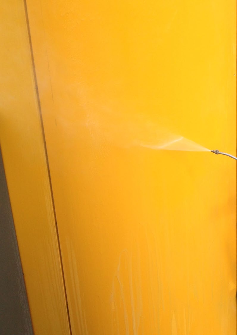
72 70

73 HELMETS AND HEAD-LAMPS CASCHI E LAMPADE FRONTALI Climbing Technology archive - photo by Soluzioni Verticali S.n.c.

74 WORK AND TREE CLIMBING HELMETS CASCHI DA LAVORO E TREE CLIMBING WORK SHELL Strong and comfortable helmet, ideal for long-lasting and demanding sessions. It presents the following features: structured shell, high impact absorbing capacity; accurate head strap adjustment turn-knob; designed to provide a good upper-eyesight when climbing; ultra-comfortable interior cosmetics; professional head lamp clips; chin strap designed to release if snagged (strength less than 25 dan); compatible with earmuffs attach kit (EARMUFFS KIT), with bayonet joint, conceived for use with earmuffs 3M-Peltor or Sperian; compatible with Visor WS in polycarbonate scratch and fog resistant, transparent (ref. 6X9410C) or smoke (6X9411C). Casco robusto e confortevole, ideale per sessioni lunghe e impegnative. Esso presenta le seguenti caratteristiche: calotta strutturata per garantire il massimo assorbimento di impatto; regolazione di precisione della fascia giro-testa e interni studiati per garantire grande comfort; progettato per garantire un ottima visuale guardando verso l alto; dotato di clip porta-lampada professionali; sottogola progettato per aprirsi in caso di urto (resistenza inferiore a 25 dan); compatibile con il supporto porta cuffie Earmuffs Kit (Ref. No. 6X939), con innesto a baionetta, ideato per l uso con cuffie, 3M-Peltor o Sperian; compatibile con la visiera Visor WS in PC con trattamento antigraffio e antiappannamento, trasparente (Ref. No. 6X9410C) o fumé (Ref. No. 6X9411C). WORK SHELL 6X X X X g Size / Taglie Material / Materiale C Standards/Normative cm / in ABS shell, PA Accessories C - EN 397:2011 EARMUFFS KIT VISOR WS VISOR WS-F VISOR WS VISOR WS Example of configuration: earmuffs not included Esempio di configurazione: cuffie non incluse 6X9410C - VISOR WS 6X9411C - VISOR WS-F 65 g X 2 EARMUFFS KIT Material / Materiale Colors / Colori PC WS (transparent) / WS-F (fumè) 6X939 C Standards/Normative C - EN 166:
; lightweight shell made of ABS and liner in")
75 HELMETS AND HEAD-LAMPS CASCHI E LAMPADE FRONTALI 3 X-ARBOR Lightweight and all-round helmets with enveloping shell that reduces the space during use. It presents the following features: provided with professional head lamp clips and slots for hearing protections with quick hooking (3M-Peltor, Sperian); lightweight shell made of ABS and liner in expanded polystyrene; comfortable foam with absorbent and washable fabric; chin strap designed to limit risk of losing helmet during a fall (strength greater than 50 dan); compatible with Visor G in PC with scratch and fog resistant treatment, transparent (Ref. No. 6X9410A) or smoke (Ref. No. 6X9411A). Casco leggero e polivalente caratterizzato da una calotta avvolgente che ne riduce l ingombro durante l uso. Esso presenta le seguenti caratteristiche: dotato di clips porta-lampada e sedi per cuffie ad aggancio rapido (es. 3M-Peltor, Sperian); calotta leggera in ABS e guscio interno in polistirene espanso; confortevole imbottitura assorbente e lavabile; sottogola progettato per ridurre il rischio di perdita del casco durante la caduta (resistenza superiore a 50 dan); compatibile con la visiera Visor G in PC con trattamento antigraffio e antiappannamento, trasparente (Ref. No. 6X9410A) o fumé (Ref. No. 6X9411A). Size / Taglie Material/Materiale C Standards/Normative X-ARBOR 6X X X X X g cm / in ABS shell, PES webbing straps C - EN 12492:2012 VISOR G VISOR G-F VISOR G Example of configuration: earmuffs not included Esempio di configurazione: cuffie non incluse 6X9410A VISOR G 6X9411A VISOR G-F 65 g X-ARBOR PADDING REPLACEMENT Material Materiale PC Colors / Colori WS (transparent) / WS-F (fumè) 6X948KIT01 C Standards/Normative C - EN 166:2001 climbingtechnology.com 73

76 WORK HELMETS, ACCESSORIES AND HEADLAMPS CASCHI DA LAVORO, ACCESSORI E LAMPADE FRONTALI X-WORK Lightweight and comfortable helmet, ideal for use on construction sites. Main characteristics: sturdy shell made of PC in order to guarantee the highest impact absorbing capacity. equipped with head lamp clips and slots for quick fitting hearing protection (e.g. 3M-Peltor, Sperian); chin strap that is designed to open in the event of an impact (resistance lower than 25 dan); removable chin strap that allows it to be used for work activities on the ground; compatible with the retractable Visor XW (Ref. No.6X943). Made in Europe. Casco leggero e confortevole, ideale per l utilizzo in cantiere. Caratteristiche principali: robusta calotta in PC per garantire il massimo assorbimento di impatto; dotato di clips porta-lampada e sedi per cuffie ad aggancio rapido (es. 3M-Peltor, Sperian); sottogola progettato per aprirsi in caso di urto (resistenza inferiore a 25 dan); sottogola removibile che ne permette l utilizzo durante l attività di lavoro a terra; compatibile con la visiera retrattile Visor XW (Ref. No.6X943). Made in Europe. Size / Taglie X-WORK 6X X X g cm / in Material / Materiale C Standards/Normative PC shell, PA Accessories C EN 397:2001 VISOR XW 6X g VISOR XW VISOR XW Material / Materiale Colors / Colori C Standards/Normative PC transparent / trasparente C - EN 166:2001 BLACK LINE CAP Windproof cap wearable under any helmet or hood. It presents the following features: made of wind proof soft-shell with excellent breathability and thermal performances; it protects efficiently against wind and cold. Made in P.R.C. Berretto antivento indossabile sotto qualsiasi casco o cappuccio: realizzato in soft-shell antivento con ottima traspirabilità ed efficienza termica; protegge efficacemente da vento e freddo. Made in P.R.C. Sizes / Taglie 7X990 UNIVERSAL 25 g 74

77 HELMETS AND HEAD-LAMPS CASCHI E LAMPADE FRONTALI 3 LUMEX LUMEX PRO Ultra-light multipurpose headlamp, ideal for rapid movements. It presents the following features: excellent value for maximum power / autonomy: 80 lm / 2 h; high performances with just 59 g weight; excellent water resistance; 4 function modes; by placing the round lens in front of the light source you get a wide beam, by removing it you get an intensive beam distance lighting; it works with one alkaline battery AA / 1,5 V (included). Made in P.R.C. Lampada frontale polivalente ultraleggera ideale per spostamenti rapidi. Presenta le seguenti caratteristiche: ottimo rapporto potenza massima / autonomia: 80 lm / 2 ore; grandi prestazioni in soli 59 g di peso; eccellente resistenza all acqua; quattro modalità di funzionamento; posizionando la lente rotonda davanti alla sorgente luminosa si ottiene un fascio di luce ampio e vicino, spostandola si ottiene un fascio ristretto e lontano; funziona con una pila alcalina AA / 1,5 V (inclusa). Made in P.R.C. High performance headlamp, conceived for long and demanding sessions. It presents the following features: excellent value for maximum power / autonomy: 185 lm /16 hrs; excellent water resistance; 6 function modes; acting on a single switch, it s possible to choose the most appropriate light intensity; acting on the zoom lens you get a wide beam for proximity lighting or an intensive beam for long distance lighting; equipped with rear red light, fixed or blinking, for increased safety on the road or at work; it works with three alkaline batteries AA / 1,5 V (included). Made in P.R.C. Lampada frontale di grandi prestazioni, concepita per sessioni lunghe e impegnative. Presenta le seguenti caratteristiche: ottimo rapporto potenza massima / autonomia: 185 lm / 16 hrs; eccellente resistenza all acqua; sei modalità di funzionamento; agendo su un unico pulsante è possibile scegliere il grado di potenza più indicato; agendo sulla lente zoom è possibile impostare una luce diffusa e vicina o una luce ristretta e lontana; dotata di luce rossa fissa o lampeggiante per maggiore sicurezza in strada o al lavoro; funziona con tre pile alcaline AA / 1,5 V (incluse). Made in P.R.C. LUMEX LUMEX PRO HD972 HD g 195 g 1 x 1,5 V 3 x 1,5 V Flux (Lm) Fascio (Lm) 80 lm / 2 hrs Flux (Lm) Fascio (Lm) 185 lm / 16 hrs Modes / Modalità 4 Modes / Modalità 6 climbingtechnology.com 75
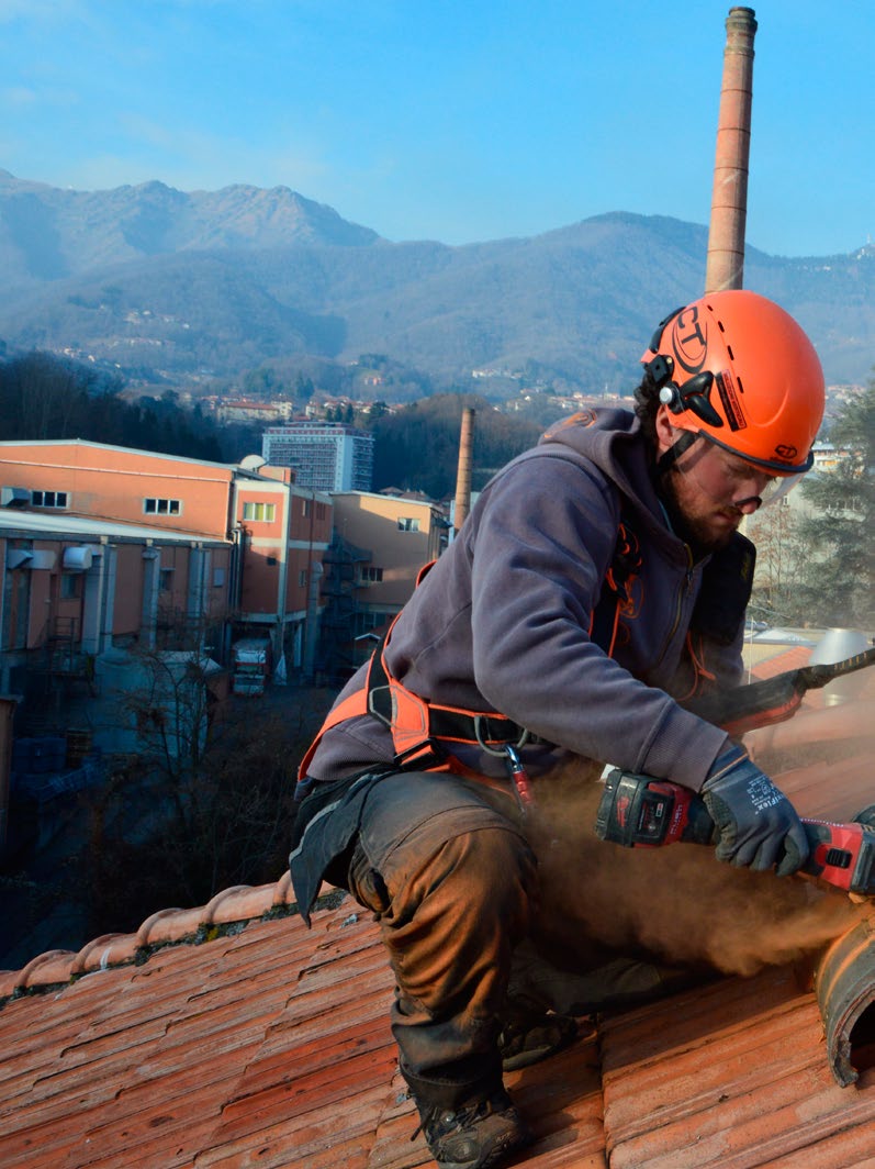
78 76

79 LANYARDS - CORDINI 2 climbingtechnology.com 77 Climbing Technology archive - photo by Soluzioni Verticali S.n.c.
80 FALL ARREST LANYARDS CORDINI ANTICADUTA FLEX-ABS Compact and lightweight fall arrest lanyards equipped with energy absorbers, high-elastic arms and possible terminator connectors. Main characteristics: elastic arms made with a reinforced band that enables a significant reduction of the encumbrance while using them and they elongate following the operator s movement; energy absorber protected in a zip-pocket; the Shelter version is equipped with light alloy double gate connectors and with a maximum gate opening of 21 mm; the Combi version is equipped with light alloy double gate connectors and with a maximum gate opening of 60 mm. All the versions, with exception to the AB900N mode, are: compliant with the requirements of the VG11, CNB/P/ for use with a fall factor 2 and use on sharp edges (r 0.5 mm); available with single or double elastic arms in two different lengths (115 / 175 cm). Made in Europe. Cordini anticaduta compatti e leggeri provvisti di assorbitore di energia a lacerazione, bracci elastici ed eventuale connettore terminale. Caratteristiche principali: bracci elastici realizzati con nastro rinforzato che permettono una consistente riduzione degli ingombri durante l utilizzo e si allungano seguendo il movimento dell operatore; assorbitore di energia protetto da custodia a zip; versione Shelter provvista di connettore in lega leggera con chiusura a doppia leva e apertura 21 mm; versione Combi provvista di connettore in lega leggera con chiusura a doppia leva e apertura 60 mm. Tutte le versioni, ad eccezione del mod. AB900N, sono: conformi alle richieste del VG11, CNB/P/ per uso con fattore di caduta 2 e uso su spigolo vivo (r 0,5 mm); disponibili con braccio singolo o doppio in due lunghezze differenti (115 / 175 cm). Made in Europe. FALL FACTOR 2 FLEX-ABS SHELTER I FLEX-ABS COMBI I 78
81 LANYARDS CORDINI 4 Name / Nome Picture / immagine Ref. no. / N Art. Full extended Length including connectors Lunghezza massima in estensione, connettori inclusi Clearance height Tirante d aria Terminal connector Connettore terminale Standards Normative C FLEX-ABS AB900N 160 g 40 cm 4,5 m - FLEX-ABS I-S 7W g 110 cm 5,2 m - FLEX-ABS I-L 7W g 170 cm 5,8 m - FLEX-ABS Y-S 7W g 110 cm 5,2 m - FLEX-ABS Y-L 7W g 170 cm 5,8 m - FLEX-ABS SHELTER I-S 7W g 105 cm 5,25 m 2C37000 XXA 22 mm FLEX-ABS SHELTER I-L 7W g 165 cm 5,85 m 2C37000 XXA 22 mm EN 355:2002 C 0333 FLEX-ABS SHELTER Y-S 7W g 105 cm 5,25 m 2C37000 XXA 22 mm FLEX-ABS SHELTER Y-L 7W g 165 cm 5,85 m 2C37000 XXA 22 mm FLEX-ABS COMBI I-S 7W g 125 cm 5,35 m 2C35300 V1A 60 mm FLEX-ABS COMBI I-L 7W g 185 cm 5,95 m 2C35300 V1A 60 mm FLEX-ABS COMBI Y-S 7W g 125 cm 5,35 m 2C35300 V1A 60 mm FLEX-ABS COMBI Y-L 7W g 185 cm 5,95 m 2C35300 V1A 60 mm climbingtechnology.com 79
82 POSITIONING AND RESTRAINT LANYARDS CORDINI DI POSIZIONAMENTO E TRATTENUTA FINCH Positioning lanyard that is adjustable, compact, easy to use and available in three different lengths (2, 3 and 5 m) with or without the terminal connector. It can be connected to the lateral attachment points (EN 358) of a full body harness, for climbing up poles or for positioning on pylons and it can also be connected to the ventral attachment point (EN 813) for positioning on inclined surfaces where there is no risk of a pendulum. Several innovative characteristics: provided with an adjuster that allows the rope to slide smoothly without snatching and, when the rope is released, it promptly locks in position. It allows for easy recovery or release of the rope even under tension; the cam has a large diameter and smooth surface that protects the rope from wear and tear and guarantees a long duration of the device; safe and easy to use: the absence of protruding parts prevents any danger of release caused by accidental touching; the Shelter version is equipped with light alloy double gate connectors and with a maximum gate opening of 21 mm; the Hook version is equipped with hot forged ergonomic light alloy double gate connectors and with a maximum gate opening of 25 mm; the Combi version is equipped with light alloy double gate connectors and with a maximum gate opening of 60 mm. Cordino di posizionamento regolabile, compatto, maneggevole e disponibile in tre lunghezze diverse (2, 3 e 5 m) con o senza connettore terminale. Può essere collegato sia agli attacchi laterali (EN 358) di un imbracatura completa, per la risalita di pali o il posizionamento su tralicci che all attacco ventrale (EN 813) per il posizionamento su piani inclinati ove non sussista il rischio di effettuare un pendolo. Diverse caratteristiche innovative: provvisto di regolatore che permette lo scorrimento fluido e senza strappi della corda e, non appena rilasciato, blocca la posizione. Consente un facile recupero o rilascio della corda anche sotto tensione; ampio diametro della camma e superficie levigata che preserva la corda dall usura e garantisce lunga durata operativa del dispositivo; sicuro e facile da utilizzare: l assenza di parti sporgenti scongiura il pericolo di rilascio accidentale per schiacciamento; versione Shelter provvista di connettore in lega leggera con chiusura a doppia leva e apertura 21 mm; versione Hook provvista di connettore ergonomico in lega leggera forgiata a caldo, con chiusura a doppia leva e apertura 25 mm; versione Combi provvista di connettore in lega leggera con chiusura a doppia leva e apertura 60 mm. FINCH device 2C46300 WBC FINCH FINCH SHELTER FINCH COMBI FINCH HOOK Length / Lunghezza 2 m Length / Lunghezza 3 m Length / Lunghezza 5 m Terminal connector Connettore terminale Finch connector Connettore Finch Standards Normative 7L L91502B0 7L L91503B0 7L L91505B0 7L91502BH 7L91502AE 7L91502BI 7L91503BH 7L91503AE 7L91503BI 7L91505BH 7L91505AE 7L91505BI - 2C37000 XXA 2C35300 V1A 2C363W0 ZP2 2C46300 WBC 2C46300 WBC 2C46300 WBC 2C46300 WBC EN 358:1999 C C
83 LANYARDS CORDINI 4 LANYARD YPSILON High strength safety rope, Ø 11 mm dynamic rope. Main features: eyelets with thimbles and double-layer stitching; dynamic rope acts as energy absorber for falls of Fall Factor less than 0,5, maximum load 100 kg and length up to 2 m. Made in Europe. Cordino di trattenuta ad alta resistenza realizzato in corda dinamica Ø 11 mm. Caratteristiche principali: asole provviste di redancia e chiuse da una cucitura a doppio strato; costruzione in corda dinamica che funge da assorbitore di energia per fattori di caduta inferiori a 0,5, massa massima di 100 kg e lunghezza del dispositivo fino a 2 m. Made in Europe. Asymmetric polyamide sling designed as dual length positioning system (30 cm and 60 cm). Main features: ideal for ascending/descending on ropes and passing intermediate anchor points; made of robust PA; joins to harness with special facilitated-tying knot. Made in Europe. Fettuccia in poliammide asimmetrica concepita come sistema di posizionamento a due misure (30 cm e 60 cm). Caratteristiche principali: ideale per la risalita e la discesa su fune e per il passaggio di frazionamenti; realizzata in robusto PA; si installa all imbracatura mediante il nodo speciale a costruzione facilitata. Made in Europe. Special knot for attach to the harness. Nodo speciale di legatura all imbraco. LANYARD Length / Lunghezza 60 cm Length / Lunghezza 80 cm 7W W g 84 g YPSILON Length / Lunghezza 100 cm Length / Lunghezza 150 cm 7W g 7W g Length / Lunghezza 1 m 7W Length / Lunghezza 200 cm 7W g < kn > 22 kn < kn > 22 kn Ø Rope / Ø Corda 16 mm Ø Rope / Ø Corda 11 mm 90 g Material / Materiale PA Material / Materiale PA Standards Normative EN 354: EN 795:2012-B Standards Normative EN 354: EN 566:2006 C C 0333 C C 0333 climbingtechnology.com 81

84 Climbing Technology archive - photo by Soluzioni Verticali S.n.c. 82

85 2 FALL ARRESTERS AND VERTICAL LIFELINES DISPOSITIVI ANTICADUTA E LINEE VITA climbingtechnology.com 83
, a working line ascender (EN 12841:2006-B) or a lanyard regulator (EN 358:1999).")
86 ROPE FALL ARRESTERS DISPOSITIVI ANTICADUTA PER CORDE EASY MOVE / EASY MOVE KIT Lightweight and easy to handle multifunctional device that can be used as a fall arrester (EN 353-2:2002 / EN 12841:2006-A), a working line ascender (EN 12841:2006-B) or a lanyard regulator (EN 358:1999). It presents several innovative characteristics: used as a fall arrester device, it allows the ascent and descent of a vertical line in complete safety and without the intervention of the user, instantly blocking itself in case of a fall. The sliding of the rope is made easier by the shape of the adjustment lever which is operated from the connector when pushed upwards during use; equipped with a two-position adjustment wheel (REST / GO) for setting the mode of use. In the GO position, the device operates in the fall arrester mode, in the REST position it can be used as an ascender or as a lanyard regulator for work in positioning; used as a fall arrester device, the device can be blocked above the user in the REST position. This allows, during the work phase, to minimizing the potential fall factor; 100 kg workload. Dispositivo multifunzionale, leggero e maneggevole, utilizzabile come anticaduta (EN 353-2:2002 / EN 12841:2006-A), risalitore (EN 12841:2006-B) o regolatore di longe (EN 358:1999). Presenta diverse caratteristiche innovative: utilizzato come anticaduta permette la salita e la discesa su una linea verticale in tutta sicurezza e senza l intervento dell utilizzatore, bloccandosi istantaneamente in caso di caduta. Lo scorrimento sulla corda è facilitato dalla forma della leva di regolazione che viene azionata dal connettore quando spinto verso l alto durante l utilizzo; dotato di una rotella di regolazione a due posizioni (REST/GO) per l impostazione della modalità di utilizzo. In posizione GO il dispositivo funziona in modalità anticaduta, in posizione REST può essere utilizzato come risalitore o come regolatore di longe per il posizionamento sul lavoro; utilizzato come anticaduta il dispositivo può essere bloccato al di sopra dell utilizzatore in posizione REST. Ciò permette, durante la fase di lavoro, di ridurre al minimo il fattore di caduta potenziale; carico di lavoro 100 kg. EASY MOVE EASY MOVE KIT 2F713 2F713K Material / Materiale Sizes / Taglie (mm) ANODIZED LIGHT ALLOY ANODIZED LIGHT ALLOY 68 x 84 mm 400 mm 190 g 380 g EN 12841:2006-A/B Ø 10,5 11 mm EN 1891-A Standards / Ø rope Norme / Ø corda EN 353-2:2002 EN 358:1999 Ø 11 mm Patron Plus 11 (174) EN 353-2:2002 Ø 11 mm Tec Static Pro (172) C C

87 FALL ARRESTERS AND VERTICAL LIFELINES DISPOSITIVI ANTICADUTA E LINEE VITA 5 INSTALLATION / INSTALLAZIONE TESTING 1 3 OK! STOP! 2 4 REST GO COUNTER WEIGHT Counter weight for keeping in tension a lifeline. Main characteristics: ideal for use with the Patron Plus 11, Worksman Evo 11, Hook, Big and Giant lifelines; robust and easy to connect to the lower part of the vertical lifeline. Made in Europe. Peso di tensionamento per linee vita verticali in corda. Caratteristiche principali: ideale per impiego con le linee vita Patron Plus 11, Worksman Evo 11, Hook, Big e Giant; robusto e facilmente collegabile alla parte inferiore della linea vita verticale. Made in Europe. COUNTER WEIGHT 7V ,5 Kg climbingtechnology.com Climbing Technology archive - photo by Ugo Pegurri 85

88 ROPE FALL ARRESTERS AND TEMPORARY LIFELINES DISPOSITIVI ANTICADUTA PER CORDE E LINEE VITA TEMPORANEE SKR-2 / SKR-2 KIT SKT LIFELINE An extremely robust, durable and functional removable fall arrester device for ropes. Main characteristics: the device slides easily along the rope in both directions without manual intervention and can be manually stopped on the rope; easy to install and uninstall anywhere on the rope; designed to guarantee grip even on dirty or icy ropes; the SKR-2 KIT version is equipped with an integrated lanyard for working at a distance from the rope; compatible with the Worksman Evo 11.0 lifeline that is available in different lengths and two colours (page 174). Dispositivo anticaduta removibile per corde, estremamente robusto, durevole e funzionale. Caratteristiche principali: il dispositivo scorre facilmente lungo la corda nelle due direzioni senza intervento manuale e può essere manualmente bloccato sulla corda; facile da installare e disinstallare in qualsiasi punto della corda; progettato per garantire la presa anche su corde sporche o ghiacciate; la versione SKR-2 KIT è provvista di longe integrata per lavorare distanti dalla corda; compatibile con la linea vita Worksman Evo 11.0 disponibile in diverse lunghezze e due colori (pag. 174). Robust and durable vertical lifeline that is equipped with a nonremovable fall arrester. Main characteristics: the device slides easily along the rope in both directions without manual intervention and can be manually stopped on the rope; made of robust black braided Ø 14mm rope; available in a wide range of lengths. Linea vita verticale robusta e durevole, provvista di anticaduta non removibile. Caratteristiche principali: il dispositivo scorre facilmente lungo la corda nelle due direzioni senza intervento manuale e può essere manualmente bloccato sulla corda; realizzata in robusta corda nera trecciata Ø 14 mm; disponibile in un ampia gamma di lunghezze. SKR-2 SKR-2 KIT Material / Materiale Sizes / Taglie (mm) Standards / Ø rope Norme / Ø corda 4F709 STAINLESS STEEL 4F709K STAINLESS STEEL 78 x 81 mm 600 mm 315 g 513 g EN 12841:2006-A Ø 10,5 11 mm EN 1891-A EN 353-2:2002 Ø 11 mm Worksman Evo 11 (176) Length / Lunghezza 10 m Length / Lunghezza 20 m Length / Lunghezza 30 m Ø Rope / Corda Standards Normative SKT LIFELINE 7L L L mm EN 353-2:2002 C C 0333 C C
89 FALL ARRESTERS AND VERTICAL LIFELINES DISPOSITIVI ANTICADUTA E LINEE VITA 5 HOOK ROD INSTALLATION / INSTALLAZIONE Telescopic pole to allow positioning and removal della HOOK LIFELINE temporary life line, provided with Ø 11 mm rope (Patron Plus 11 model) and connector with 60 mm opening. The pole has a specially-shaped tip for holding the metal ring of the life line connector, to hold the connector open and allow it to be positioned on a raised attachment point, which would otherwise be inaccessible. The life line can be easily removed with a similar operation. Length adjustable 2,4-10 m. Made in Europe. EN795 ANCHOR 2 3 Pertica telescopica che consente la collocazione e la rimozione della linea vita temporanea HOOK LIFELINE, provvista di corda Ø 11 mm (mod. Patron Plus 11) e connettore con apertura 60 mm. La pertica è provvista di un puntale sagomato che, agganciandosi all anello metallico del connettore della linea vita, lo mantiene aperto e ne consente la collocazione in un punto di attacco elevato, altrimenti inaccessibile. La linea vita può essere facilmente rimossa compiendo la medesima operazione effettuata per l installazione. Lunghezza regolabile da 2,4 a 10 m. Made in Europe. 1 REMOVING / RIMOZIONE 2 1 HOOK LIFELINE HOOK ROD 7L926 ROD14 Material / Materiale - FIBREGLASS Length / Lunghezza 10 m 2,4 10 m 60 - Standards / Ø rope Norme / Ø corda EN 795:2012-B / Ø 11 mm EN 1891-A - climbingtechnology.com 87

90 TELESCOPIC POLES AND TEMPORARY TEXTILE LIFELINES PERTICHE TELESCOPICHE E LINEE VITA TEMPORANEE TESSILI FIX ROD KIT ROD Telescopic pole to allow positioning and removal of the built-in temporary life line or reach an operator who has been injured during a rescue manoeuvre. The pole has a built-in connector which can be held open by pulling the thin service cord to connect to the desired attachment ring. When used from below, the rod remains in position during use to then be easily removed at the end of the activity. Equipped with rope Patron Plus 11 and a connector with large opening (60 mm). Length adjustable 1 to 2,8 m. Made in Europe. Pertica telescopica che consente di collocare e rimuovere la linea vita temporanea integrata o avvicinare un operatore infortunato durante la manovra di recupero. La pertica è provvista di un connettore integrato che può essere mantenuto aperto mediante il cordino di servizio e conseguentemente agganciato al punto di attacco da raggiungere. In caso di utilizzo per accesso ad una postazione di lavoro dal basso la pertica rimane in posizione durante l uso per poi essere velocemente rimossa a fine attività. Provvista di corda Patron Plus 11 e di un connettore a larga apertura (60 mm). Lunghezza regolabile da 1 a 2,8 m. Made in Europe. Telescopic poles with a maximum length of 10 m that are equipped with hooking supports for vertical lifelines. Main characteristics: allows you to connect a temporary lifeline to an otherwise inaccessible elevated attachment point; the connector of the lifeline is inserted into the mounting and the mechanism keeps the lever open, releasing it when the connector is in position; the Kit Rod L model is equipped with a compatible support for the Big Lifeline and the Giant Lifeline; the Kit Rod F model is equipped with a compatible support for the Large and D-Shape connectors. Made in Europe. Pertiche telescopiche, di lunghezza massima 10 m, dotate di supporti di aggancio per linee vita verticali. Caratteristiche principali: consentono di collegare una linea vita temporanea ad un punto di attacco elevato, altrimenti inaccessibile; il connettore della linea vita viene inserito nel supporto di aggancio che ne mantiene aperta la leva, rilasciandola al momento dell installazione; il modello Kit Rod L è provvisto di un supporto compatibile con le linee vita Big Lifeline e Giant Lifeline; il modello Kit Rod F è provvisto di un supporto compatibile con i connettori Large e D-Shape. Made in Europe. KIT ROD F FIX ROD KIT ROD L Material / Materiale 7L927 FIBREGLASS KIT ROD F KIT ROD L Length / Lunghezza 1 2,8 m ROD11 ROD12 60 Material / Materiale Length / Lunghezza * Hooking devices Dispositivi di Aggancio FIBREGLASS FIBREGLASS 2,4 10 m 2,4 10 m Standards / Ø rope Norme / Ø corda EN 795:2012-B / Ø 11 mm EN 1891-A 3C716 3C717 88
91 FALL ARRESTERS AND VERTICAL LIFELINES DISPOSITIVI ANTICADUTA E LINEE VITA 5 FIX ROD INSTALLATION / INSTALLAZIONE KIT ROD INSTALLATION / INSTALLAZIONE ATTACHMENT POINT 2 OK! 2 EN795 ANCHOR 1 OK! BIG LIFELINE Vertical lifeline equipped with the Patron Plus 11 Ø 11 mm rope and the Big connector. Main characteristics: suitable for use with the Easy Move, the SKR-2 and the SKR-2 KIT fall arrester devices; easy to install using the KIT ROD L pole; maximum connector aperture of 60 mm. Linea vita verticale equipaggiata con corda Patron Plus 11 Ø 11 mm e connettore terminale Big. Caratteristiche principali: adatta all uso con i dispositivi anticaduta Easy Move, SKR-2 e SKR-2 KIT; facilmente installabile mediante la pertica KIT ROD L; apertura connettore 60 mm. GIANT LIFELINE Vertical lifeline that is equipped with the Patron Plus 11 Ø 11 mm rope and the Giant terminal connector. Main characteristics: suitable for use with the Easy Move, SKR-2 and SKR-2 KIT fall arrester devices; easy to install using the KIT ROD L telescopic pole; 110 mm connector opening. Length / Lunghezza 10 m BIG LIFELINE 7L GIANT LIFELINE 7L Linea vita verticale equipaggiata con corda Patron Plus 11 Ø 11 mm e connettore terminale Giant. Caratteristiche principali: adatta all uso con i dispositivi anticaduta Easy Move, SKR-2 e SKR-2 KIT; facilmente installabile mediante la pertica KIT ROD L; apertura connettore 110 mm. Ø Rope / Corda Standards Normative Connector Connettore 11 mm 11 mm EN 1891-A EN 362:2004-A/T EN 362:2004-A/T climbingtechnology.com 89

92 PERMANENT STAINLESS STEEL LIFELINES LINEE VITA PERMANENTI IN ACCIAIO INOX WALL LIFELINE Installation Kit for the vertical wall lifeline. Made completely of stainless steel, to be mounted onto the wall using the supports that are provided. It is equipped with an Ø 8 mm stainless steel cable. It is recommended to use the SKC KIT fall arrester device. Kit di installazione per linea vita verticale a muro. Completamente realizzata in acciaio inox, si fissa alla parete per mezzo dei supporti in dotazione. Provvista di cavo Ø 8 mm in acciaio inox. Si consiglia l uso dei dispositivi anticaduta SKC KIT. C-LADDER LIFELINE Installation Kit for the central ladder lifeline. Made completely of stainless steel, to be mounted in a central position on the ladder using the supports that are provided. It is equipped with an Ø 8 mm stainless steel cable. It is recommended to use the SKC EVO, SKC or the SKC-G fall arrester device. Kit di installazione per linea vita centrale su scala. Completamente realizzata in acciaio inox, si fissa al centro della scala per mezzo dei supporti in dotazione. Provvista di cavo Ø 8 mm in acciaio inox. Si consiglia l uso dei dispositivi anticaduta SKC EVO, SKC o SKC-G. 4L903 4L904 Length / Lunghezza On request Length / Lunghezza On request Standards Normative EN Standards Normative EN Components parts Componenti A D E F x 2 x 1 x 1 x 8 G H I x 1 x 1 x 4 Components parts Componenti B D E G x 2 x 1 x 1 x 1 H I x 1 x 4 90


93 Use only with an SKC device; Utilizzare solo con dispositivo SKC; À utiliser seulement avec le dispositif SKC; Nur mit dem Gerät SKC verwenden; Utilizar solamente con dispositivo SKC Read the manufacturer s instructions; Leggere le istruzioni del fabbricante; Lire les recommandations du fabricant; Die Herstelleranweisungen lesen; Leer las instrucciones del constructor Use a harness with a EN 361 sternal attachment point; Indossare imbracatura con attacco sternale EN 361; Porter un harnais avec point d attache sternal EN 361; Gurte mit EN 361 sternalem Anschlagpunkt verwenden; Utilizar arnés anticaída con anclaje esternal EN 361 Direction of use and fall clearance; Direzione di utilizzo e tirante d aria; Direction d utilisation et tirant d air; Anwendungsrichtung und Sturzraum; Dirección de uso y tirante de aire Maximum No. of users; N massimo di utilizzatori; N maximal d utilisateurs; Max. Anwenderzahl; Número máximo de usuarios Date and No. of the installation; Data e numero dell installazione; Date et n d installation; Datum u. Installationsnr; Fecha y n de instalación Periodic check Controllo periodico Contrôle périodique Regelmäßige Kontrolle Control periódico FALL ARRESTERS AND VERTICAL LIFELINES DISPOSITIVI ANTICADUTA E LINEE VITA 5 S-LADDER LIFELINE Installation Kit for the side ladder lifeline. Made completely of stainless steel, to be mounted onto one side of the ladder using the supports that are provided. It is equipped with an Ø 8 mm stainless steel cable. It is recommended to use the SKC KIT fall arrester device. Kit di installazione per linea vita laterale su scala. Completamente realizzata in acciaio inox, si fissa su un lato della scala per mezzo dei supporti in dotazione. Provvista di cavo Ø 8 mm in acciaio inox. Si consiglia l uso dei dispositivi anticaduta SKC KIT. A B C D E EN 353-1/2 VERTICAL FALL ARRESTER LINE / LINEA VITA ANTICADUTA VERTICALE / LIGNE DE VIE VERTICALE ANTICHUTE / AUFFANG- EINRICHTUNG VERTIKALE LINIE / LINEA VERTICAL ANTICAIDA ID H F G I 4L905 SKC 4F706 SKC KIT 4F706K SKC EVO 4F716K Length / Lunghezza On request Standards Normative Components parts Componenti x C2 x D1 x E1 x 2 x H1 x 1 x 1 x I4 x 4 x 1 EN SKC KAR 4F70601 x G1 x 1 climbingtechnology.com 91

94 EN 353-1:2014 EN 353-2:2002 AISI 304 MADE IN ITALY Patented EN 353-1:2014 EN 353-2:2002 AISI 304 MADE IN ITALY Patented CABLE FALL ARRESTERS DISPOSITIVI ANTICADUTA PER CAVI IN ACCIAIO SKC EVO Patented removable fall arrester device for use with Ø 8 mm galvanized/ stainless steel cables. Main characteristics: equipped with an integrated lanyard with an energy absorber; quick and easy to attach and detach from the cable; innovative double action opening system: to open the device, first of all you must press the safety lever (1) and then push the locking lever (2) upwards. The device can only be opened if the action is carried out in the sequential way to therefore eliminate the risk of accidental opening; even if an error occurs it is safe: the locking lever does not open if the device is turned upside down thus preventing the improper installation onto the cable; lightweight, compact and ergonomic; workload ranging from 50 to 140 kg. Dispositivo anticaduta removibile brevettato per cavi in acciaio zincato/ inox Ø 8 mm. Caratteristiche principali: provvisto di longe integrata con assorbitore di energia; facile e veloce da agganciare e sganciare dal cavo; innovativo sistema di apertura double action: per aprire il dispositivo è necessario dapprima premere la levetta di sicurezza (1) e successivamente spingere verso l alto la leva di bloccaggio (2). Il dispositivo si apre solo se l azione è svolta in modo sequenziale eliminando così il pericolo di un apertura accidentale; sicuro anche in caso di errore: la leva di bloccaggio non si apre se il dispositivo è capovolto impedendone così un errata installazione sul cavo; leggero, compatto ed ergonomico; carico di lavoro compreso fra 50 e 140 kg. WORK LOAD CARICO DI LAVORO kg EN 353-1:2014 EN 353-2:2002 INSTALLATION / INSTALLAZIONE 1 UP ALTO HAUT AUF 2 UP ALTO HAUT AUF SKC EVO OK! SKC EVO PATENT SKC EVO Material / Materiale Sizes / Dimensioni 4F716K STAINLESS STEEL 85 x 190 mm 465 g Ø Cable / Cavo Standards Normative STAINLESS / GALVANIZED STEEL Ø 8 mm EN 353-1: EN 353-2:2002 C C

95 FALL ARRESTERS AND VERTICAL LIFELINES DISPOSITIVI ANTICADUTA E LINEE VITA 5 SKC Patented removable fall arrester device for use with Ø 8 mm stainless steel cables. Main characteristics: robust, durable and easy to use; to remove the device from the cable it is necessary to disengage the connector, thus avoiding the danger of accidental release. Dispositivo anticaduta removibile brevettato per cavi in acciaio inox Ø 8 mm. Caratteristiche principali: robusto, durevole e facile da utilizzare; per rimuovere il dispositivo dal cavo è necessario sganciare il connettore evitando così il pericolo di sgancio accidentale. SKC SKC-G Patented removable fall arrester device for use with Ø 8 mm galvanized steel cables. Main characteristics: robust, durable and easy to use; to remove the device from the cable it is necessary to disengage the connector, thus avoiding the danger of accidental release. Dispositivo anticaduta removibile brevettato per cavi in acciaio galvanizzato Ø 8 mm. Caratteristiche principali: robusto, durevole e facile da utilizzare; per rimuovere il dispositivo dal cavo è necessario sganciare il connettore evitando così il pericolo di sgancio accidentale. PATENT SKC-G *NEW CERTIFICATION Following several accidents caused by bad functioning of the fall stop device in situations not provided for in the EN 353-1:2002, in March 2010, on the recommendation of the British authorities, the European Commission decided to consider incomplete and unsafe to EN 353-1:2002. For this reason, additional tests have been added to the EN 353-1:2002. Our fall stop devices SKC, SKC KIT, SKC KAR e SKC-G KAR have successfully passed these rigorous tests at the APAVE laboratory in Fontaine (France), obtaining the certification according to the requirements of EN 353-1:2002, the relevant articles of pr EN 353-1:2008 and CEN/TC160 VG1 RfU document. *NUOVA CERTIFICAZIONE A seguito di svariati incidenti dovuti al malfunzionamento dei dispositivi in situazioni non contemplate nella EN 353-1:2002, a marzo 2010, su segnalazione delle autorità inglesi, la Commissione Europea ha ritenuto incompleta e poco sicura la normativa EN 353-1:2002. Per questa motivazione sono stati aggiunti test complementari alla EN 353-1:2002. I nostri dispositivi anticaduta SKC, SKC KIT, SKC- G e SKC-G KIT hanno superato con successo, presso il laboratorio APAVE di Fontaine (Francia), questi severi test, ottenendo così la certificazione secondo i requisiti della EN 353-1:2002, gli articoli pertinenti della pren 353-1:2008 e del documento CEN/TC160 VG1 RfU F F706Z0 Material / Materiale Sizes / Dimensioni STAINLESS STEEL STAINLESS STEEL 88 x 80 mm 88 x 80 mm 380 g 380 g Ø Cable / Cavo Standards Normative STAINLESS STEEL Ø 8 mm GALVANIZED STEEL Ø 8 mm EN 353-1:2002* - EN 353-2:2002 EN 353-1:2002* C C 0333 C 0333 climbingtechnology.com 93

96 CABLE FALL ARRESTERS DISPOSITIVI ANTICADUTA PER CAVI IN ACCIAIO *NEW CERTIFICATION Following several accidents caused by bad functioning of the fall stop device in situations not provided for in the EN 353-1:2002, in March 2010, on the recommendation of the British authorities, the European Commission decided to consider incomplete and unsafe to EN 353-1:2002. For this reason, additional tests have been added to the EN 353-1:2002. Our fall stop devices SKC, SKC KIT, SKC KAR e SKC-G KAR have successfully passed these rigorous tests at the APAVE laboratory in Fontaine (France), obtaining the certification according to the requirements of EN 353-1:2002, the relevant articles of pr EN 353-1:2008 and CEN/TC160 VG1 RfU document. *NUOVA CERTIFICAZIONE A seguito di svariati incidenti dovuti al malfunzionamento dei dispositivi in situazioni non contemplate nella EN 353-1:2002, a marzo 2010, su segnalazione delle autorità inglesi, la Commissione Europea ha ritenuto incompleta e poco sicura la normativa EN 353-1:2002. Per questa motivazione sono stati aggiunti test complementari alla EN 353-1:2002. I nostri dispositivi anticaduta SKC, SKC KIT, SKC- G e SKC-G KIT hanno superato con successo, presso il laboratorio APAVE di Fontaine (Francia), questi severi test, ottenendo così la certificazione secondo i requisiti della EN 353-1:2002, gli articoli pertinenti della pren 353-1:2008 e del documento CEN/TC160 VG1 RfU SKC KAR Patented removable fall arrester device for use with Ø 8 mm stainless steel cables. Main characteristics: robust, durable and easy to use; equipped with an oval shaped tied-on connector with twist-lock closure; to remove the device from the cable it is necessary to disengage the connector, thus avoiding the danger of accidental release. Dispositivo anticaduta removibile brevettato per cavi in acciaio inox Ø 8 mm. Caratteristiche principali: robusto, durevole e facile da utilizzare; provvisto di connettore imperdibile di forma ovale e chiusura twist-lock; per rimuovere il dispositivo dal cavo è necessario sganciare il connettore evitando così il pericolo di sgancio accidentale. PATENT SKC KAR SKC-G KAR Patented removable fall arrester device for use with Ø 8 mm galvanized/stainless steel cables. Main characteristics: robust, durable and easy to use; equipped with an oval shaped tied-on connector with twist-lock closure; to remove the device from the cable it is necessary to disengage the connector, thus avoiding the danger of accidental release. Dispositivo anticaduta removibile brevettato per cavi in acciaio inox e galvanizzato Ø 8 mm. Caratteristiche principali: robusto, durevole e facile da utilizzare; provvisto di connettore imperdibile di forma ovale e chiusura twist-lock; per rimuovere il dispositivo dal cavo è necessario sganciare il connettore evitando così il pericolo di sgancio accidentale. PATENT SKC-G KAR 4F F706Z1 Material / Materiale Sizes / Dimensioni STAINLESS STEEL 88 x180 mm Material / Materiale Sizes / Dimensioni STAINLESS STEEL 88 x180 mm 565 g 565 g Ø Cable / Cavo STAINLESS STEEL Ø 8 mm Ø Cable / Cavo STAINLESS / GALVANIZED STEEL Ø 8 mm Connectors Connettori 3C525 Connectors Connettori 3C525 Standards Normative EN 353-1:2002* EN 353-2:2002 Standards Normative EN 353-1:2002* C C 0333 C C

97 FALL ARRESTERS AND VERTICAL LIFELINES DISPOSITIVI ANTICADUTA E LINEE VITA 5 SKC KIT / SKC KIT PLUS Patented removable fall arrester devices for use with Ø 8 mm stainless steel cables. Main characteristics: tied-on device thanks to the connection cable equipped with a lanyard with an energy absorber that reduces the impact force consequent to a fall; to remove the device from the cable it is necessary to disengage the connector, thus avoiding the danger of accidental release of the line; the SKC KIT model has a working load of 100 kg and the SKC KIT PLUS version has a working load of 136 kg. Dispositivi anticaduta removibili brevettati per cavi in acciaio inox Ø 8 mm. Caratteristiche principali: dispositivo imperdibile grazie al cavetto di collegamento al connettore; dotati di longe con assorbitore di energia che riduce la forza di arresto conseguente ad una caduta; per rimuovere il dispositivo dal cavo è necessario scollegare il connettore evitando così il pericolo di sgancio accidentale dalla linea; il modello SKC KIT presenta un carico di lavoro di 100 kg, la versione SKC KIT PLUS di 136 kg. PATENT SKC KIT SKC KIT PLUS 4F706K0 4F706K2 Material / Materiale Length / Lunghezza STAINLESS STEEL STAINLESS STEEL 400 mm 310 mm 575 g 555 g Ø Cable / Cavo Standards Normative STAINLESS STEEL Ø 8 mm EN 353-1:2002* (Use for Kg) EN 353-2:2002 STAINLESS STEEL Ø 8 mm EN 353-1:2002* Use for Kg C C 0333 C 0333 climbingtechnology.com 95

98 Climbing Technology archive - photo by Soluzioni Verticali S.n.c. 96

99 2 RETRACTABLE FALL ARRESTERS AND SELF RETRACTING LANYARDS DISPOSITIVI ANTICADUTA RETRATTILI climbingtechnology.com 97
100 RETRACTABLE FALL ARRESTER DEVICES FROM 1,5 TO 4 m DISPOSITIVI ANTICADUTA RETRATTILI DA 1,5 A 4 m SERIES 600 / SERIES 700 SERIES 600 SERIES 700 Extremely lightweight and compact retractable fall arrest device for work at height. Main characteristics: compared to traditional energy absorbing textile lanyards, they allow for greater freedom of movement and have a short fall clearance; the terminal connector can be either attached to an anchor point EN 795 or to the sternal or dorsal ring of a fall arrest harness EN 361 (Fig. 1); a combined braking system (mechanical brake + textile energy absorber) which enables a soft fall arrest regardless of the length of the extracted line; the casing and drum are made from composite material; equipped with an integrated Dyneema 15 mm fibre line with a length of 1.5 m (600 Series model) or 2 m (700 Series model); equipped with a superior swivel and a light alloy terminal connector. Made in Europe. Dispositivi anticaduta retrattili estremamente leggeri e compatti per lavoro in altezza. Caratteristiche principali: rispetto ai classici cordini con assorbitore di energia tessile consentono una maggiore libertà di movimento ed un tirante d aria contenuto; il connettore terminale può essere indifferentemente collegato ad un punto di ancoraggio EN 795 o all anello sternale o dorsale di un imbracatura anticaduta EN 361 (Fig. 1); sistema di frenata combinato (freno meccanico + assorbitore di energia tessile) che consente un arresto morbido della caduta a prescindere dalla lunghezza di linea estratta; involucro e tamburo in materiale composito; dotati di linea vita integrata in dyneema da 15 mm e lunghezza 1,5 m (mod. Series 600) o 2 m (mod. Series 700); provvisti di girello superiore e connettore terminale in lega leggera. Made in Europe. A B SERIES 600 SERIES 700 REVERSIBILITY: two modes of use REVERSIBILITÀ: due modalità di utilizzo 8G6000PQ*V 8G7000PQ*V 0,76 kg 0,81 kg Length Lunghezza 1,5 m 2 m 21 mm 21 mm *= For the choice of the top link connections see table on page 104. *= Per la scelta della configurazione della connessione superiore vedere tabella a pag Standards Normative EN 360:2002 C C

101 RETRACTABLE FALL ARRESTERS AND SELF RETRACTING LANYARDS DISPOSITIVI ANTICADUTA RETRATTILI 6 SERIES 102 / SERIES 104 SERIES 102 SERIES 104 Compact and lightweight retractable fall arrest device for work at height. Main characteristics: the operator is able to go up and come down safely both to and from the place of work detaining a possible fall; a combined braking system (mechanical brake + textile energy absorber) which enables a soft fall arrest regardless of the length of the extracted line; the casing and drum are made from composite material; equipped with an integrated Dyneema 15 mm fibre line with a length of 2.5 m (102 Series model) or 4 m (104 Series model); equipped with a superior swivel and a light alloy terminal connector. Made in Europe. Dispositivi anticaduta retrattili compatti e leggeri per lavoro in altezza. Caratteristiche principali: permettono all operatore di salire e scendere in sicurezza da e verso il luogo di lavoro arrestandone un eventuale caduta; sistema di frenata combinato (freno meccanico + assorbitore di energia tessile) che consente un arresto morbido della caduta a prescindere dalla lunghezza di linea estratta; involucro e tamburo in materiale composito; dotati di linea vita integrata in dyneema da 15 mm e lunghezza 2,5 m (mod. Series 102) o 4 m (mod. Series 104); provvisti di girello superiore e connettore terminale in lega leggera. Made in Europe. SERIES 102 SERIES 104 8G1020PQ*V 8G1040PQ*V 0,88 kg 1,14 kg Length Lunghezza 2,5 m 4 m 21 mm 21 mm *= For the choice of the top link connections see table on page 104. *= Per la scelta della configurazione della connessione superiore vedere tabella a pag Standards Normative EN 360:2002 C C 0333 climbingtechnology.com 99

102 RETRACTABLE FALL ARRESTER DEVICES FROM 7 TO 15 m DISPOSITIVI ANTICADUTA RETRATTILI DA 7 A 15 m SERIES 105 / SERIES 107 SERIES 105 SERIES 107 Robust retractable fall arrest device designed for temporary work at height. Main characteristics: the operator is able to go up and come down safely both to and from the place of work detaining a possible fall; advanced braking system that does not obstruct the operator s movement; the casing and drum are made from composite material; the 105 model is equipped with an integrated Dyneema 15 mm fibre line with a length of 7 m and the 107 model is instead equipped with an integrated galvanized steel cable Ø 5 mm with a length of 7 m; equipped with terminal connectors equipped with an integrated swivel and a fall indicator. Made in Europe. Dispositivi anticaduta retrattili robusti concepiti per il lavoro temporaneo in quota. Caratteristiche principali: permettono all operatore di salire e scendere in sicurezza da e verso il luogo di lavoro arrestandone un eventuale caduta; sistema di frenata evoluto che non ostacola il movimento dell operatore; involucro e tamburo in materiale composito; il modello 105 è dotato di linea vita integrata in dyneema da 15 mm di lunghezza 7 m; il modelli 107 è provvisto invece di cavo in acciaio zincato Ø 5 mm di lunghezza 7 m; provvisti di connettore terminale dotato di girello integrato e indicatore di caduta. Made in Europe. SERIES 105 Linea in Dyneema. Dyneema fiber line. SERIES 107 Steel cable line. Linea in acciaio. SERIES 105 SERIES 107 8G105 0G ** V 8G105 0H ** V 8G107 0G ** V 8G107 0H ** V 0G Twist-lock connector made of light alloy. Connettore twist-lock in lega leggera. Ref. no. / N Art. 2C337. 0H Double gate connector made of steel. Connettore a doppia leva in acciaio. Ref. no. / N Art. 3C358. Length Lunghezza 3,10 kg 3,30 kg 3,50 kg 3,70 kg 7 m 7 m 7 m 7 m 20 mm 17 mm 20 mm 17 mm **= For the choice of the top link connections see table on page 104. **= Per la scelta della configurazione della connessione superiore vedere tabella a pag Standards Normative EN 360:2002 C C
103 RETRACTABLE FALL ARRESTERS AND SELF RETRACTING LANYARDS DISPOSITIVI ANTICADUTA RETRATTILI 6 SERIES 110 / SERIES 115 SERIES 110 SERIES 115 Robust retractable fall arrest device designed for temporary work at height or for installation on ladders. Main characteristics: the operator is able to go up and come down safely both to and from the place of work detaining a possible fall; equipped with a built in handle for easy transportation; advanced braking system that does not obstruct the operator s movement; the casing and drum are made from composite material; equipped with an integrated galvanized steel cable Ø 5 mm fibre line with a length of 10 m (Series 110 model) or 15 m (Series 115 model); equipped with terminal connectors equipped with an integrated swivel and a fall indicator. Made in Europe. Dispositivi anticaduta retrattili robusti concepiti per il lavoro temporaneo in quota o per l installazione su scale. Caratteristiche principali: permettono all operatore di salire e scendere in sicurezza da e verso il luogo di lavoro arrestandone un eventuale caduta; provvisti di maniglia per facilitarne il trasporto; sistema di frenata evoluto che non ostacola il movimento dell operatore; involucro e tamburo in materiale composito; dotati di linea vita integrata in cavo in acciaio zincato Ø 5 mm e lunghezza 10 m (mod. Series 110) o 15 m (mod. Series 115); provvisti di connettore terminale dotato di girello integrato e indicatore di caduta. Made in Europe. SERIES 110 SERIES 115 0G Twist-lock connector made of light alloy. Connettore twist-lock in lega leggera. Ref. no. / N Art. 2C337. 0H Double gate connector made of steel. Connettore a doppia leva in acciaio. Ref. no. / N Art. 3C358. Length Lunghezza 8G110 0G ** V 8G110 0H ** V 8G115 0G ** V 8G115 0H ** V 6,90 kg 7,10 kg 7,30 kg 7,50 kg 10 m 10 m 15 m 15 m 20 mm 17 mm 20 mm 17 mm **= For the choice of the top link connections see table on page 104. **= Per la scelta della configurazione della connessione superiore vedere tabella a pag Standards Normative EN 360:2002 C C 0333 climbingtechnology.com 101

104 RETRACTABLE AND HOISTING FALL ARRESTER DEVICES DISPOSITIVI ANTICADUTA RETRATTILI E DI SOLLEVAMENTO SERIES 205 / 210 / 215 SERIES 205 SERIES 210 SERIES 215 Compact and lightweight retractable fall arrest device for work at height. Main characteristics: the workload has been increased to 136 kg; the operator is able to go up and come down safely both to and from the place of work detaining a possible fall; advanced braking system that does not obstruct the operator s movement; the casing and drum are made from composite material; the 205 model is equipped with an integrated Dyneema 15 mm fibre line with a length of 7 m and the 210 and 215 models are instead equipped with an integrated galvanized steel cable Ø 5 mm with a length of 10 and 15 m; equipped with terminal connectors equipped with an integrated swivel and a fall indicator. Made in Europe. Dispositivi anticaduta retrattili robusti concepiti per il lavoro in quota. Caratteristiche principali: carico di lavoro incrementato a 136 kg; permettono all operatore di salire e scendere in sicurezza da e verso il luogo di lavoro arrestandone un eventuale caduta; sistema di frenata evoluto che non ostacola il movimento dell operatore; involucro e tamburo in materiale composito; il modello 205 è dotato di linea vita integrata in dyneema da 15 mm di lunghezza 7 m; i modelli 210 e 215 sono provvisti invece di cavo in acciaio zincato Ø 5 mm di lunghezza 10 e 15 m; provvisti di connettore terminale dotato di girello integrato e indicatore di caduta. Made in Europe. WORK LOAD CARICO DI LAVORO 136 kg 0G Twist-lock connector made of light alloy. Connettore twist-lock in lega leggera. Ref. no. / N Art. 2C337. 0H Double gate connector made of steel. Connettore a doppia leva in acciaio. Ref. no. / N Art. 3C358. SERIES 205 SERIES 210 SERIES 215 8G205 0G ** V 8G205 0H ** V 8G210 0G ** V 8G210 0H ** V 8G215 0G ** V 8G215 0H ** V 3,25 kg 3,45 kg 6,90 kg 7,10 kg 7,30 kg 7,50 kg **= For the choice of the top link connections see table on page 104. **= Per la scelta della configurazione della connessione superiore vedere tabella a pag Length Lunghezza Standards Normative 7 m 7 m 10 m 10 m 15 m 15 m 20 mm 17 mm 20 mm 17 mm 20 mm 17 mm EN 360:2002 C C
 or as a lifting device (EN 1496-B).")
105 RETRACTABLE FALL ARRESTERS AND SELF RETRACTING LANYARDS DISPOSITIVI ANTICADUTA RETRATTILI 6 SERIES 119 Bifunctional device that has been specifically developed for work in confined spaces. Extremely robust and versatile, it can be used as a retractable fall arrester (EN 360) or as a lifting device (EN 1496-B). Main characteristics: when used in the EN 360 mode it allows the operator to safely descend and ascend both to and from the place of work arresting a possible fall; when used in the mode EN 1496-B it allows the operator to lift another operator using the specific lever for a maximum of 15 m and to lower them for a maximum of 2 m; equipped with an integrated galvanized Ø 5 mm steel cable with a length of 15 m; equipped with terminal connectors equipped with an integrated swivel and a fall indicator; compatible with the KITSUP0119 and KITSUPA119 supports for the installation on the Tris (page 152) and Arachnipod (page 151) anchor devices. Made in Europe. Dispositivo bifunzionale sviluppato appositamente per il lavoro in spazi confinati. Estremamente robusto e versatile, può esse re utilizzato come anticaduta retrattile (EN 360) o come dispositivo di sollevamento (EN 1496-B). Caratteristiche principali: utilizzato in modalità EN 360, permette all operatore di scendere e risalire in sicurezza da e verso il luogo di lavoro arrestandone un eventuale caduta; utilizzato in modalità EN 1496-B, consente ad un operatore di sollevare un altro operatore mediante l apposita leva per un massimo di 15 m e di calarlo per un massimo di 2 m; dotato di linea vita integrata in cavo in acciaio zincato Ø 5 mm e lunghezza 15 m; provvisto di connettore terminale dotato di girello integrato e indicatore di caduta; compatibile con i supporti KITSUP0119 e KITSUPA119 per l installazione sui dispositivi di ancoraggio Tris (pag. 152) e Arachnipod (pag. 151). Made in Europe. KIT SUPA119 (pag. 151) KIT SUP0119 (pag. 152) SERIES 119 8G119 0G ** V 8G119 0H ** V 10,80 kg 11,00 kg 0G Twist-lock connector made of light alloy. Connettore twist-lock in lega leggera. Ref. no. / N Art. 2C337. 0H Double gate connector made of steel. Connettore a doppia leva in acciaio. Ref. no. / N Art. 3C358. Length Lunghezza Standards Normative 15 m 15 m 20 mm 17 mm EN 360:2002 EN 1496:2006-B **= For the choice of the top link connections see table on page 104. **= Per la scelta della configurazione della connessione superiore vedere tabella a pag C C 0333 climbingtechnology.com 103

106 DESCENDER FOR RESCUE / FALL ARRESTER DEVICES DISPOSITIVI DI DISCESA PER SALVATAGGIO / ANTICADUTA UPPER CONNECTIONS FOR RETRACTABLE FALL ARRESTERS, HOISTING DEVICES CONNESSIONI SUPERIORI PER ANTICADUTA RETRATTILI, DISPOSITIVI DI SOLLEVAMENTO NAME / NOME PICTURE EXTENSION REF. DESCRIPTION/ DESCRIZIONE REF. N / ART. N Big wide opening connector already equipped with an upper swivel. Compatible with the models: SERIES 600; TOP LINK BIG (*) E 700; 102; 104. Connettore a larga apertura Big per modelli già 2C35300 V1A provvisti di girello superiore. Compatibile con i modelli: SERIES 600; 700; 102; 104. TOP LINK BIG ASYMMETRIC + (**) SE Big wide opening connector and swivel Compatible with the models: SERIES 105; 107; 110; 115; 205; 210; 215; 119; 129. Connettore a larga apertura Big e girello. Compatibile con i modelli: SERIES 105; 107; 110; 115; 205; 210; 215; 119; D792T5 + 2C35300 V1A TOP LINK STEEL SG UNIVERSAL + (**) YD Stainless steel screwgate connector with 150 cm lanyard. Compatible with all models. Connettore in acciaio con ghiera a vite e fettuccia da 150 cm: Compatibile con tutti i modelli. 7W C4630A Climbing Technology archive - photo by Soluzioni Verticali S.n.c. 104
107 Nessuna parte di questa pubblicazione può essere riprodotta o trasmessa in qualsiasi modo. Aludesign S.A. Tutti i diritti riservati. PR022-8G600CTIT rev Nessuna parte di questa pubblicazione può essere riprodotta o trasmessa in qualsiasi modo. Aludesign S.A. Tutti i diritti riservati. PR022-8G600CTIT rev Nessuna parte di questa pubblicazione può essere riprodotta o trasmessa in qualsiasi modo. Aludesign S.A. Tutti i diritti riservati. PR022-8G600CTIT rev NOME E COGNOME Compilare la presente scheda seguendo la procedura di ispezione, il materiale fotografico e le istruzioni fornite dal fabbricante, scaricabili dal sito Il giudizio dell esaminatore in merito all entità dell anomalia deve essere basato su criteri oggettivi ed in base all addestramento specifico ricevuto. Il produttore declina ogni responsabilità conseguente a informazioni inesatte riportate dall utilizzatore o dal revisore. Nessuna parte di questa pubblicazione può essere riprodotta o trasmessa in qualsiasi modo. Aludesign S.A. Tutti i diritti riservati. FIRMA PR022-8G600CTIT rev RETRACTABLE FALL ARRESTERS AND SELF RETRACTING LANYARDS DISPOSITIVI ANTICADUTA RETRATTILI 6 PERIODIC CHECKS It is obligatory that the retractable fall arrester devices are subjected to a thorough periodic check carried out by a competent person, periodically or at any time if: there is even the slightest doubt about the good working order of the device; if the device shows malfunctions during the visual and function inspection carried out before, after and during each use; in case the fall indicator is activated; if the identification sheet and /or markings are lost or illegible; if there is no certainty about the past usage of the device. The thorough check must be carried out only from a person expressly authorized by the manufacturer, at least every 12 months, with normal/ standard use or every 6 months if the device has been used in harsh conditions that could cause corrosion of the metal parts, the deterioration of the textile parts or cause material buildup that could make the operation of the mechanisms uncertain of which the device is made up of. If the PPE has been used to arrest a fall, the fall indicator is activated or the cover of the hexagonal tread of the head of a fixing screw of the shell is not intact, the use of the PPE must be immediately suspended. The outcome of the thorough check, including potential repairs, must be reported on the device s identification card that is found in the instructions for use and on the checklist included in the inspection manual. The User Instructions and a copy of the check list must be returned to the User that will keep them together with the device for when the next inspection is due. On completion of the verification procedure, the device may be declared: FIT FOR USE, UNFIT FOR USE or TO BE CHECKED/ TO KEEP CONTROLLED. Note. A device that is TO BE CHECKED/ TO KEEP CONTROLLED is a device that presents minor defects to pay attention to during inspections before and after use and because of this the periodic inspection can be anticipated as opposed to the 12 or 6 month period foreseen. CONTROLLO PERIODICO I dispositivi anticaduta retrattili devono obbligatoriamente essere sottoposti ad un controllo periodico approfondito eseguito da persona competente, periodicamente o in qualsiasi momento qualora: esista il minimo dubbio sul buon funzionamento dell attrezzo; il controllo visivo e funzionale da eseguire prima, durante e dopo ogni utilizzo riveli la benché minima anomalia; l indicatore di caduta sia attivato; la scheda identificativa e/o le marcature manchino o siano illeggibili; non si abbia certezza circa l uso pregresso del dispositivo. Il controllo deve essere eseguito esclusivamente da tecnici espressamente abilitati dal costruttore almeno una volta ogni 12 mesi che si riducono a 6 se il dispositivo è stato utilizzato in condizioni difficili che potrebbero favorire la corrosione delle parti metalliche, il deterioramento delle parti tessili o il deposito di materiale che potrebbero rendere incerto il funzionamento dei meccanismi che compongono l attrezzo. Se il DPI è stato utilizzato per l arresto di una caduta, l indicatore di caduta è attivato o il riempimento dell impronta esagonale della testa di una vite di fissaggio dei gusci non è intatto l impiego del DPI deve essere immediatamente sospeso. L esito del controllo approfondito, incluse le eventuali riparazioni, devono essere riportate sulla scheda di identificazione del dispositivo che si trova all interno delle istruzioni d uso e sulla check-list inclusa nel manuale di ispezione. Istruzioni d uso e copia della check-list devono essere consegnate all utilizzatore finale che avrà cura di conservarle e consegnarle assieme al dispositivo per il controllo successivo. Al termine della procedura di controllo il dispositivo potrà essere dichiarato: IDONEO ALL USO, NON IDONEO ALL USO o DA VERIFICARE/TENERE CONTROLLATO Nota. Un dispositivo DA VERIFICARE/TENERE CONTROLLATO è un dispositivo che presenta difetti lievi a cui prestare attenzione durante i controlli prima e dopo l uso e per cui il controllo periodico successivo può essere anticipato rispetto ai 12 o 6 mesi previsti. MANUALE DI MANUTENZIONE SERIES 600 ISPEZIONE DEL DISPOSITIVO DI PROTEZIONE DPI MANUALE DI MANUTENZIONE SCHEDA DI ISPEZIONE PER CONTROLLO PERIODICO 1 - Verifica generale e storica. MANUALE DI MANUTENZIONE SERIES 600 ISPEZIONE DEL DISPOSITIVO DI PROTEZIONE DPI IDENTIFICAZIONE DEL DISPOSITIVO MANUALE DI MANUTENZIONE SCHEDA DI ISPEZIONE PER CONTROLLO PERIODICO Verificare la presenza e la leggibilità dei dati di marcatura, in particolare il marchio CE e la normativa EN di riferimento Verificare che il dispositivo non abbia superato la vita di immagazzinamento e/o di utilizzo prevista Verificare che il dispositivo sia integro e completo in ogni sua parte (si consiglia il confronto con un prodotto nuovo). Verificare che l attrezzo sia stato revisionato regolarmente, i controlli vengono riportati nell ID card del dispositivo che si trova all interno delle istruzioni d uso (che devono sempre accompagnare l anticaduta) Verificare che il dispositivo non appaia modificato fuori dall unità produttiva o revisionato in luogo non autorizzato Verificare che il dispositivo non abbia subito un evento eccezionale (es. caduta dall alto, urto violento, etc.). Anche se nessun difetto o degradazione fosse constatabile all esame visivo, la sua resistenza iniziale potrebbe essere diminuita seriamente. Marchio commerciale Produttore Securit Prodotto O SERIES 600 O SERIES 700 O SERIES 102 O SERIES 104 Numero di serie Anno di fabbricazione Data di acquisto / / Data del primo utilizzo / / Data di scadenza / / Normative di Utente (società, nome EN 360 riferimento e indirizzo) CONTROLLO DEL DISPOSITIVO 11) ASSEMBLAGGIO 11.1 Montaggio boccola perno e rinforzo ancoraggio. 2 - Controllo visivo e funzionale Se il riempimento dell impronta esagonale di una delle viti di fissaggio dei gusci non dovesse essere intatto l attrezzo potrebbe essere stato modificato o revisionato da personale non autorizzato, in tal caso deve essere sostituito (fare Controllo delle molle dei denti. riferimento alla sezione Descrizione dispositivo e distinta base per verificare quale deve essere l aspetto del sigillo In evidenza gli anelli di arresto intatto). del perno dei denti Applicare una leggera pressione sul tamburo per mantenerlo in posizione nel guscio, estrarre per qualche cm la fettuccia, bloccare il tamburo in modo che non possa ruotare e sfilare il guida fettuccia dalla sua sede nel guscio Pulire l attrezzo con aria compressa, eventualmente rimuovere polvere e sporco residui con un panno morbido. Se necessario utilizzare una spugna leggermente imbevuta in acqua tiepida senza immergere direttamente il dispositivo nell acqua, successivamente asciugare il dispositivo con un panno morbido. Rimozione del guida fettuccia. Prestare attenzione 3 - Controllo dell assorbitore di energia. per evitare la fuoriuscita accidentale della molla Verificare che i fili delle cuciture non siano rotti, tagliati o sfilacciati. La fettuccia che copre l occhiello non deve essere Valutare se rimuovere il tamburo dal guscio lato molla in base alle condizioni generali del dispositivo, il tamburo danneggiata. La guaina termoretraibile che copre la parte terminale della linea deve essere intatta. deve essere rimosso sicuramente se: Se l assorbitore di energia è danneggiato significa che il dispositivo è stato utilizzato per l arresto di una caduta, quindi è - il tamburo è danneggiato e deve essere sostituito; necessario sostituirlo con uno nuovo. - il guscio lato molla è danneggiato e deve essere sostituito; - la fettuccia non si riavvolge correttamente (controllo funzionale). Se si ritiene che lo smontaggio o la sostituzione del tamburo dal guscio lato molla non è necessario passare direttamente al montaggio del nuovo guida fettuccia (fase 9.4). Come fatto in precedenza applicare una leggera pressione sul tamburo per mantenerlo in posizione nel guscio, impugnare la parte finale della fettuccia e lasciare ruotare il tamburo in senso orario per scaricare la molla di recupero del tamburo. Eliminare il guida fettuccia (sostituirlo con quello del ricambio 8G600-KIT 1). CONTROLLO DEL DISPOSITIVO 1) VERIFICA GENERALE E STORICA 1.1 Controllo leggibilità etichette. 1.2 Controllo vita utile. 1.3 Controllo integrità. 1.4 Controllo assenza di manomissioni. 1.5 Controllo indicatore di caduta. 2) CONTROLLO VISIVO E FUNZIONALE 2.1 Controllo integrità riempimento impronta esagonale. 2.2 Pulizia esterna attrezzo. 3) CONTROLLO DELL ASSORBITORE DI ENERGIA 3.1 Controllo indicatore di caduta. 4) CONTROLLO VISIVO E FUNZIONALE DI CONNETTORI E GIRELLI 4.1 Controllo assenza manomissioni connettore. 4.2 Controllo integrità connettore. 4.3 Controllo funzionale connettore. 4.4 Controllo assenza manomissioni girello. 4.5 Controllo integrità girello. 4.6 Controllo funzionale girello. 5) ispezione della fettuccia e controlli funzionali 5.1 Controllo assenza di usura della fettuccia. 5.2 Controllo scorrimento e recupero fettuccia. 5.3 Controllo bloccaggio attrezzo Montaggio gruppo freno Controlli funzionali Montaggio e controllo girello. 12) RIPRISTINO DELL IMPRONTA ESAGONALE 12.1 Ripristino dell impronta esagonale. DISPOSITIVO DISPOSITIVO DISPOSITIVO DA VERIFICARE / ESITO DEL CONTROLLO IDONEO ALL USO NON IDONEO ALL USO TENERE CONTROLLATO Data del controllo / / Motivo del controllo Controllo periodico Controllo eccezionale Note (difetti rilevati, riparazioni effettuate o altre informazioni pertinenti) Nome e firma del responsabile del controllo Data del controllo successivo / / 9 I 15 III Sample pages taken from an inspection procedure. Pagine di esempio estratte da una procedura di ispezione. Sample pages taken from an inspection sheet. Pagine di esempio estratte da una scheda di ispezione. climbingtechnology.com 105
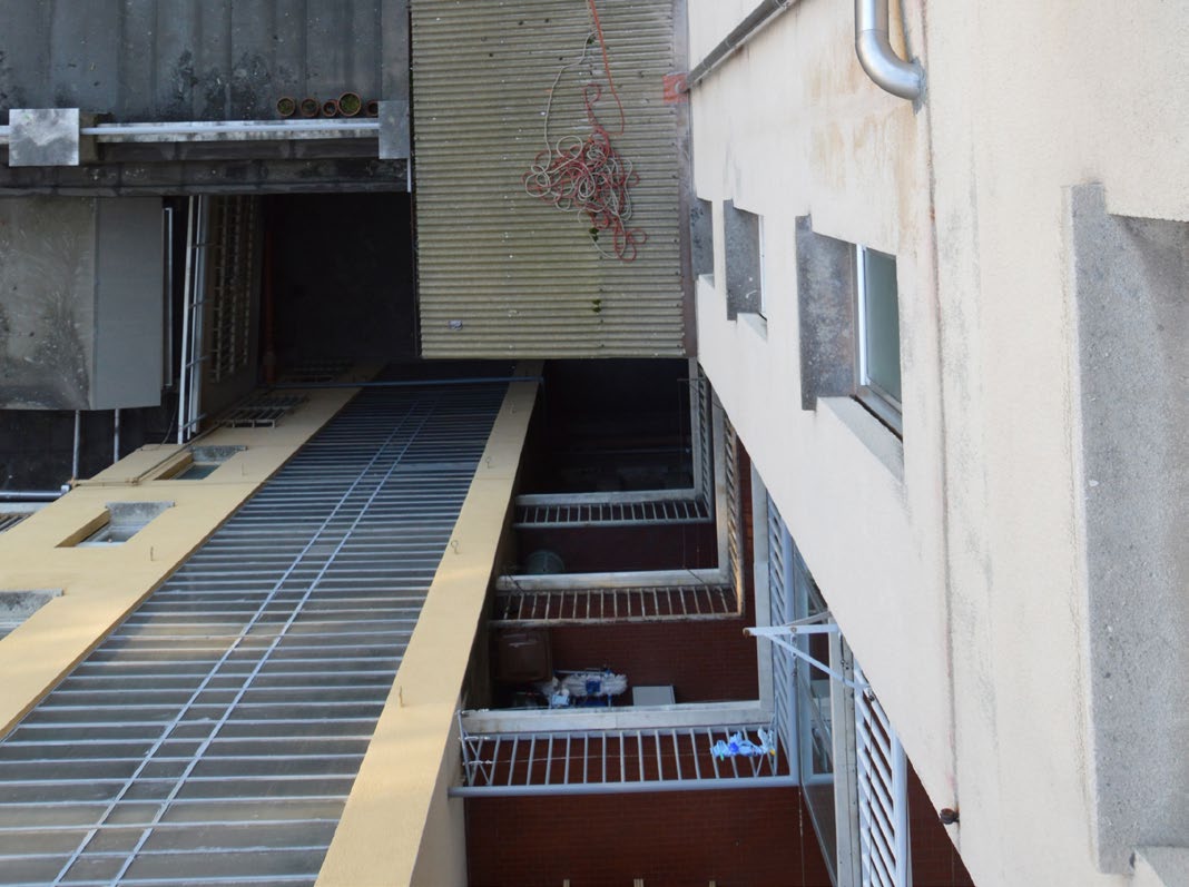
108 106

109 CONNECTORS AND QUICK-LINKS CONNETTORI E MAGLIE RAPIDE 2 climbingtechnology.com Climbing Technology archive - photo by Soluzioni Verticali S.n.c. 107
110 LIGHT ALLOY HOT FORGED OVAL AND HMS CONNECTORS CONNETTORI IN LEGA LEGGERA OVALI E HMS FORGIATI A CALDO PILLAR PRO Hot-forged light alloy carabiners with an oval shape. Particularly suitable for recovery and rescue operations. They present the following features: elevated workloads: major axis strength 25 kn and minor axis strength 12kN; oval shaped for optimal positioning of pulleys and clamps, shaped for better grip during use; new improved section in the most used points, for an increased resistance during the contact with the equipment and rope; catch-free closure that prevents accidental snagging during use; available with or without the ACL system, which allows you to attach it to the belay loop on the harness, stabilizing it and preventing the possibility of cross loading; the HC model with the special anodized hard anti-wear, is ideal for intense and prolonged use; available with a straight gate, with a screw gate, twist-lock gate and a triplex gate. Moschettoni di forma ovale in lega leggera forgiati a caldo, particolarmente indicati per manovre di recupero e soccorso. Presentano le seguenti caratteristiche: elevati carichi di tenuta: 25 kn sull asse maggiore e 12 sull asse minore; forma ovale per il posizionamento ottimale di carrucole e bloccanti, sagomata per una migliore impugnatura durante l uso; nuova sezione maggiorata nei punti di maggior lavoro, per una maggiore resistenza al contatto con attrezzi e corde; chiusura catch-free che evita l impiglio accidentale durante l uso; disponibili con o senza sistema ACL, che permette di fissarli all anello di servizio dell imbracatura, stabilizzandoli e prevenendo la possibilità di carico sull asse minore; il modello HC presenta una speciale anodizzazione anti-usura, ideale per usi intensivi e prolungati; disponibili con ghiera a vite, ghiera twist-lock e ghiera triplex. PILLAR PRO SGL HC Ref. no. / N Art. 2C3960L SYB Special anodized hard anti-wear. Speciale anodizzazione anti-usura. PILLAR PRO SG PILLAR PRO SGL / HC PILLAR PRO TG PILLAR PRO TGL PILLAR PRO WG Material / Materiale Sizes / Dimensioni Gates / Ghiera 2C39600 YDB 2C39600 XZD 2C3960L ZSF 2C3960L SYB 2C39800 YLB 2C39800 XZD ANODIZED LIGHT ALLOY 2C3980L XRA 2C3980L XZD 2C39700 ZPE 2C39700 XZD 111 x 64 mm 111 x 64 mm 111 x 64 mm 111 x 64 mm 111 x 64 mm SCREW GATE SCREW GATE - Spring bar TRIPLEX TRIPLEX - Spring bar TWIST-LOCK 22 mm 68 g 22 mm 71 g 21 mm 73 g 21 mm 76 g 21 mm 72 g kn kn kn kn kn Standards Normative EN 362:2004-B EN 12275:2013-B C C 0333 C 0333 C 0333 C 0333 C 0333 EN 362:2004-A/T EN 12275:2013-B EN 362:2004-B EN 12275:2013-B EN 362:2004-A/T EN 12275:2013-B EN 362:2004-B EN 12275:2013-B Other features Altre caratteristiche 108
111 CONNECTORS AND QUICK-LINKS CONNETTORI E MAGLIE RAPIDE 7 CONCEPT Light alloy hot forged connectors, particularly suitable for use with the Munter hitch and for the insertion of multiple ropes and slings. Main characteristics: emphasized double T beam construction for an excellent weight / strength ratio; especially shaped and lightened for a better grip; wide opening in a compact design; catch free closure that avoids accidental snagging during use; available with or without the ACL lever, which allows you to stabilize the connector and avoids the risk of cross loading; the Concept SGL HC model has a special anodized wear-proof hard coat, ideal for intensive and prolonged use available with a screwgate, the automatic twist-lock gate or the triplex gate. Connettori in lega leggera forgiati a caldo, particolarmente indicati per l impiego con il nodo mezzo barcaiolo e per l inserimento multiplo di corde e fettucce. Caratteristiche principali: accentuato profilo a doppia T, per un eccellente rapporto peso / resistenza; forma lavorata e alleggerita, per una migliore impugnatura; ampia apertura in un design compatto; chiusura catch free che evita l impiglio accidentale durante l uso; disponibili con o senza levetta ACL, che permette di stabilizzarli ed evita il rischio di carico sull asse minore; il modello Concept SGL HC presenta una speciale anodizzazione antiusura, ideale per usi intensivi e prolungati; disponibili con ghiera a vite, ghiera automatica twist-lock e ghiera triplex. CONCEPT SGL HC Ref. no. / N Art. 2C3380L SYB Special anodized hard anti-wear. Speciale anodizzazione anti-usura. CONCEPT SG CONCEPT SGL / HC CONCEPT TG CONCEPT TGL CONCEPT WG Material / Materiale Sizes / Dimensioni Gates / Ghiera 2C33800 WNE 2C3380L XTZ 2C3380L SYB 2C33900 XPH 2C3390L XPH 2C39900 ZPE ANODIZED LIGHT ALLOY 105 x 73 mm 105 x 73 mm 105 x 73 mm 105 x 73 mm 105 x 73 mm SCREW GATE SCREW GATE - Spring bar TRIPLEX TRIPLEX - Spring bar TWIST-LOCK 21 mm 74 g 21 mm 77 g 21 mm 81 g 21 mm 84 g 21 mm 80 g kn kn kn kn kn Standards Normative EN 362:2004-B EN 12275:2013-H C C 0333 Other features Altre caratteristiche EN 362:2004-A/T EN 12275:2013-H EN 362:2004-B EN 12275:2013-H EN 362:2004-A/T EN 12275:2013-H EN 362:2004-B EN 12275:2013-H climbingtechnology.com 109

112 LIGHT ALLOY OVAL AND D SHAPED CONNECTORS CONNETTORI IN LEGA LEGGERA DI FORMA OVALE E A D PILLAR Profile adapt to link equipment like large pulleys; high strength can be used safely also as a karabiner for progression; symmetrical body and optimal rope radius; catch-free system to allow clean, snag free connections; individually tested at 12 kn; the PILLAR WG HC model with the special anodized hard anti-wear, is ideal for intense and prolonged use. For expert climbers that need reliable sound equipment. Ideally designed for use as a harness connector, placement of equipment and hauling, attachment for retractable fall arresters. Profilo adatto al collegamento di dispositivi tipo le grandi carrucole; alta resistenza può essere usato come moschettone da progressione; forma simmetrica, raggio di incidenza per la corda ottimale; sistema catch-free che permette maggiore fluidità durante il moschettonaggio; testati individualmente a 12 kn; modello PILLAR WG HC con speciale anodizzazione dura anti-usura, ideale per usi intensivi e prolungati. Per esperti della verticalità che richiedono un equipaggiamento solido ed affidabile. Ideato per impiego come connettore da imbraco, piazzamento di attrezzi, calata, collegamento del dispositivo retrattile. PILLAR WG HC Ref. no. / N Art. 2C46400 SYB Special anodized hard anti-wear. Speciale anodizzazione anti-usura. PILLAR SG PILLAR WG / HC PILLAR TG 2C46300 WBC 2C46300 XTB 2C46300 XZD 2C46400 ZPE 2C46400 XTB 2C46400 SYB 2C44600 YRC 2C44600 XZD 2C44600 XTB Material / Materiale Sizes / Dimensioni Gates / Ghiera ANODIZED LIGHT ALLOY 111 x 62 mm 111 x 62 mm 111 x 62 mm SCREW GATE TWIST-LOCK TRIPLEX 21 mm 75 g 21 mm 80 g 21 mm 82 g kn kn kn Standards Normative EN 362:2004-B EN 12275:2013-B C C 0333 Other features Altre caratteristiche EN 362:2004-B EN 12275:2013-B EN 362:2004-B EN 12275:2013-B 110

113 CONNECTORS AND QUICK-LINKS CONNETTORI E MAGLIE RAPIDE 7 D-SHAPE NIMBLE Compact but high strength; catch-free system to allow clean, snag free connections; individually tested at 12 kn. For expert climbers that need reliable solid equipment. Ideal to be used as a terminal connection for lanyards or to set up a belay. Compatto ma offre grande resistenza; sistema catch-free che permette maggiore fluidità durante il moschettonaggio; testati individualmente a 12 kn. Per esperti della verticalità che richiedono un equipaggiamento solido ed affidabile. Ideale come terminale di longe o per attrezzare una sosta. Extremely compact, with a good gate clearance; catch-free system to allow clean, snag free connections; individually tested at 12 kn. For expert climbers that want a tiny weight-less multipurpose karabiner. Molto compatto, con un buon passaggio; sistema catch-free che permette maggiore fluidità durante il moschettonaggio; testati individualmente a 12 kn. Per esperti della verticalità che vogliono un moschettone compatto leggero e multiuso. D-SHAPE SG D-SHAPE WG D-SHAPE TG NIMBLE SG 2C47600 XTN 2C47600 XTB 2C47600 XZD 2C44900 ZPE 2C47700 YRC 2C47700 XTB 2C47700 XZD 2C44200 WFB Material / Materiale Sizes / Dimensioni Gates / Ghiera ANODIZED LIGHT ALLOY 110 x 62 mm 110 x 62 mm 110 x 62 mm SCREW GATE TWIST-LOCK TRIPLEX Material / Materiale Sizes / Dimensioni Gates / Ghiera ANODIZED LIGHT ALLOY 105 x 61 mm SCREW GATE 19 mm 75 g 19 mm 80 g 19 mm 80 g 20 mm 57 g kn kn kn kn Standards Normative EN 362:2004-B EN 12275:2013-B C C 0333 EN 362:2004-B EN 362:2004-B EN 12275:2013-B Standards Normative EN 362:2004-B EN 12275:2013-B Other features Altre caratteristiche C C 0333 Other features Altre caratteristiche climbingtechnology.com 111
114 LIGHT ALLOY HMS AND WIDE BASED CONNECTORS CONNETTORI IN LEGA LEGGERA HMS E BASE LARGA LARGE SNAPPY Large opening, and wide space for multiple connections and use of pulleys; tough profile high strength; catch-free system to allow clean, snag free connections; individually tested at 12 kn. For expert climbers that need reliable sound equipment. Ideally designed to connect a retractable fall arrester to an anchor point, when you need to insert several slings and ropes or for rigging. Grande apertura e ampio spazio per collegamenti multipli e uso di carrucole; profilo robusto che offre grande resistenza; sistema catch-free che permette maggiore fluidità durante il moschettonaggio; testati individualmente a 12 kn. Per esperti della verticalità che richiedono un equipaggiamento solido ed affidabile. Ideale per collegare all ancoraggio un anticaduta retrattile, quando occorre l inserimento multiplo di corde e fettucce o per manovre. Ergonomic for handling with one hand; tough profile high strength; compact size and with optiomal wide radius for the rope; catch-free system to allow clean, snag free connections; individually tested at 12 kn. For expert climbers that need reliable sound equipment. Ideally designed for use with a munter hitch knot, multiple insertion of slings and ropes. Ergonomico da impugnare e aprire con una mano; profilo robusto che offre grande resistenza; compatto nelle dimensioni e con ottimo raggio di incidenza per la corda sistema catch-free che permette maggiore fluidità durante il moschettonaggio; testati individualmente a 12 kn. Per esperti della verticalità che richiedono un equipaggiamento solido ed affidabile. Ideale per impiego con nodo mezzo barcaiolo, per l inserimento multiplo di corde e fettucce. LARGE SG LARGE TG SNAPPY SG SNAPPY TG Material / Materiale Sizes / Dimensioni Gates / Ghiera 2C45500 WBG 2C45500 XTB 2C45500 XZD ANODIZED LIGHT ALLOY 2C46500 YRC 2C46500 XTB ANODIZED LIGHT ALLOY 116 x 79 mm 116 x 79 mm SCREW GATE TRIPLEX 26 mm 92 g 26 mm 98 g 2C45900 WBG 2C45900 XTB 2C45900 XZD ANODIZED LIGHT ALLOY 2C46100 YRC 2C46100 XTB 2C46100 XZD 112 x 73 mm 112 x 73 mm SCREW GATE 22 mm 86 g TWIST-LOCK 22 mm 90 g kn kn kn kn Standards Normative EN 362:2004-B EN 12275:2013-B EN 362:2004-B EN 12275:2013-B EN 362:2004-B EN 12275:2013-H EN 362:2004-B EN 12275:2013-H C C 0333 C 0333 C 0333 Other features Altre caratteristiche 112

115 CONNECTORS AND QUICK-LINKS CONNETTORI E MAGLIE RAPIDE 7 AXIS HMS Shape guarantees correct axial loading relative to rope and other devices; large size and ample width to allow the securing of more than one rope, slings or devices and rope manoeuvres in general; accentuated double-t profile, for an excellent weight/load ratio; lightened and shaped form for improved ease of holding; catch-free closure to avoid accidental tangling during use; available with or without ACL system, which allows attachment to the harness s belay loop, preventing cross loading; available with screw or triplex gate; individually tested at 12 kn. For professional climbers that need reliable sound equipment. Ideally designed when you need to insert several slings, ropes, devices or for rope manoeuvres. Forma progettata per garantire un corretto lavoro in asse della corda o dei dispositivi; grande dimensione e ampio spazio per facilitare l ancoraggio di più corde, fettucce, dispositivi e le manovre di corda in generale; accentuato profilo a doppia T, per un eccellente rapporto peso / resistenza; forma alleggerita e sagomata, per una migliore impugnatura; chiusura catch-free che evita l impiglio accidentale durante l uso; disponibili con o senza sistema ACL, che permette di fissarli all anello di servizio dell imbracatura, stabilizzandoli e prevenendo la possibilità di carico sull asse minore; disponibili con ghiera a vite o ghiera triplex; testati individualmente a 12 kn. Per esperti della verticalità che richiedono un equipaggiamento solido ed affidabile. Ideale quando occorre l inserimento multiplo di corde, fettucce, dispositivi o per manovre di corda. AXIS HMS SG AXIS HMS SGL AXIS HMS TG AXIS HMS TGL Material / Materiale Sizes / Dimensioni Gates / Ghiera 2C38500 ZZB 2C3850L ZZB 2C38600 XPE 2C3860L XPE ANODIZED LIGHT ALLOY 121 x 82 mm SCREW GATE SCREW GATE - Spring bar TRIPLEX TRIPLEX - Spring bar 24 mm 80 g 24 mm 83 g 23 mm 86 g 23 mm 89 g kn kn kn kn Standards Normative EN 362:2004-B EN 12275:2013-H C C 0333 Other features Altre caratteristiche EN 362:2004-A/T EN 12275:2013-H EN 362:2004-B EN 12275:2013-H EN 362:2004-A/T EN 12275:2013-H climbingtechnology.com 113

116 LIGHT ALLOY GALVANIZED STEEL CONNECTORS CONNETTORI IN LEGA LEGGERA E IN ACCIAIO ZINCATO KEY Shaped body ideal as rope lanyards terminal connector; ideal to connect the sit harness to the chest harness; catch-free system to allow clean, snag free connections; individually tested at 12 kn. For making a directional connection having a dedicated slot for the rope. The shaped body helps to orientate the load on the back spine. Corpo sagomato ideale come terminale di cordini; ideale come collegamento tra imbraco basso e pettorale; sistema catch-free che permette maggiore fluidità durante il moschettonaggio; testati individualmente a 12 kn. Per realizzare collegamenti direzionali corpo sagomato con sede per la corda. La forma sagomata facilita l orientamento del carico sull asse maggiore. Climbing Technology archive - photo by Soluzioni Verticali S.n.c. Material / Materiale Sizes / Dimensioni Gates / Ghiera Standards Normative KEY SG 2C44400 XTB ANODIZED LIGHT ALLOY 2C44500 YRC 2C44500 XTB 115 x 81 mm 115 x 81 mm SCREW GATE TRIPLEX 20 mm 82 g 20 mm 89 g 22 kn 22 kn EN 362:2004-A/T KEY TG EN 362:2004-A/T C C

117 CONNECTORS AND QUICK-LINKS CONNETTORI E MAGLIE RAPIDE 7 PILLAR STEEL Profile adapt to link equipment like large pulleys; high strength construction, made of hardened carbon steel; symmetrical body and optimal rope radius; catch-free system to allow clean, snag free connections; individually tested at 12 kn. For use where durability and strength are important. Ideally designed for use as a harness connector, placement of equipment and hauling, attachment of retractable fall arresters. Profilo adatto al collegamento di dispositivi tipo le grandi carrucole; alta resistenza, realizzato in acciaio al carbonio temprato; forma simmetrica, raggio di appoggio per la corda ottimale; sistema catch-free che permette maggiore fluidità durante il moschettonaggio; testati individualmente a 12 kn. Per impieghi dove contano resistenza e durabilità. Ideato per impiego come connettore da imbraco, piazzamento di attrezzi, calata, collegamento del dispositivo retrattile. SNAPPY STEEL Ergonomic to handle and open with one hand; tough profile high strength; compact size then very functional; catch-free system to allow clean, snag free connections; individually tested at 12 kn. For expert climbers that need reliable sound equipment. Ergonomico da impugnare e aprire con una mano sola; profilo robusto che offre grande resistenza; compatto nelle dimensioni ma di grande funzionalità; sistema catch-free che permette maggiore fluidità durante il moschettonaggio; testati individualmente a 12 kn. Per esperti della verticalità che richiedono un equipaggiamento solido e affidabile. PILLAR STEEL SG PILLAR STEEL TG SNAPPY STEEL SG SNAPPY STEEL TG 3C4630A 3C4460A 3C4590A 3C4610A Material / Materiale Sizes / Dimensioni Gates / Ghiera ZINC PLATED STEEL 110 x 61 mm 110 x 61 mm SCREW GATE TRIPLEX 22 mm 180 g 22 mm 193 g ZINC PLATED STEEL 119 x 78 mm 119 x 78 mm SCREW GATE TRIPLEX 22 mm 237 g 22 mm 250 g kn kn kn kn Standards Normative EN 362:2004-M EN 12275:2013-B C C 0333 EN 362:2004-M EN 362:2004-M EN 12275:2013-H EN 362:2004-M EN 12275:2013-H Other features Altre caratteristiche - C 0333 climbingtechnology.com 115

118 GALVANIZED STEEL AND STAINLESS STEEL CONNECTORS CONNETTORI IN ACCIAIO ZINCATO E INOX LARGE STEEL Wide opening, massive space for multiple connections including pulleys; tough profile high strength; catch-free system to allow clean, snag free connections; individually tested at 12 kn. For use where durability and strength are important. Ideally designed for tough rigging, placement of heavy equipment and hauling, attachment of retractable fall arresters or rescue systems. Grande apertura e ampio spazio per collegamenti multipli e carrucole; profilo robusto che offre grande resistenza; sistema catch-free che permette maggiore fluidità durante il moschettonaggio; testati individualmente a 12 kn. Per impieghi dove contano resistenza e durabilità. Ideale per calate molto impegnative, posizionamento di attrezzi, collegamento del dispositivo retrattile e sistemi di soccorso. D-SHAPE STEEL Asymmetric shape for correct load orientation; tough profile high strength; compact size then very functional; catch-free system to allow clean, snag free connections; individually tested at 12 kn. For expert climbers that need reliable sound equipment. Forma asimmetrica per un efficace orientamento del carico; profilo robusto che offre grande resistenza; compatto nelle dimensioni ma di grande funzionalità ; sistema catch-free che permette maggiore fluidità durante il moschettonaggio; testati individualmente a 12 kn. Per esperti della verticalità che richiedono un equipaggiamento solido e affidabile. LARGE STEEL SG LARGE STEEL TG D-SHAPE STEEL SG D-SHAPE STEEL TG 3C4550A 3C4650A 3C4760A 3C4770A Material / Materiale Sizes / Dimensioni Gates / Ghiera ZINC PLATED STEEL 116 x 79 mm 116 x 79 mm SCREW GATE TRIPLEX 25 mm 253 g 25 mm 260 g ZINC PLATED STEEL 110 x 63 mm 110 x 63 mm SCREW GATE TRIPLEX 19 mm 178 g 19 mm 189 g kn kn kn kn Standards Normative EN 362:2004-M EN 362:2004-M EN 362:2004-M EN 12275:2013-B EN 362:2004-M C C 0333 C

119 CONNECTORS AND QUICK-LINKS CONNETTORI E MAGLIE RAPIDE 7 OVAL S-STEEL Symmetrical shape ideal for use as a harness karabiner; traditional gate closure ideal for use in dirty envirments and mud; individually tested at 12 kn. Ideal for use in chemically aggressive environments, off-shore operations, diving. Forma simmetrica ideale come connettore da imbraco; sistema di chiusura tradizionale, ideale in ambienti; sporchi e fangosi; testati individualmente a 12 kn. Per impieghi in atmosfere chimicamente aggressive, operazioni marittime, immersioni. D-SHAPE S-STEEL Asymmetrical shape for a correct orientation of the load; traditional gate closure ideal for use in dirty enviroments and mud; individually tested at 12 kn. Ideal for use in chemically aggressive environments, off-shore operations, diving. Forma asimmetrica ideale per il corretto orientamento del carico; sistema di chiusura tradizionale, ideale in ambienti sporchi e fangosi; testati individualmente a 12 kn. Per impieghi in atmosfere chimicamente aggressive, operazioni marittime, immersioni. LARGE S-STEEL Large opening wide surface ideal for multiconnections of ropes webbing and pulleys; catch-free system to allow clean, snag free connections; available also with captive bar (4C465IC); individually tested at 12 kn. Ideal for use in chemically aggressive environments, off-shore operations, diving. Forma asimmetrica ideale per il corretto orientamento del carico; sistema catch-free che permette maggiore fluidità durante il moschettonaggio; disponibile inoltre con barretta capacitiva (4C465IC); testati individualmente a 12 kn. Per impieghi in atmosfere chimicamente aggressive, lavoro in mare, immersioni. OVAL S-STEEL D-SHAPE S-STEEL SG D-SHAPE S-STEEL TG LARGE S-STEEL TGI 4C524 4C528 4C530 4C465I0 Material / Materiale Sizes / Dimensioni Gates / Ghiera POLISHED STAINLESS STEEL 108 x 58 mm SCREW GATE POLISHED STAINLESS STEEL 110 x 63 mm 110 x 63 mm SCREW GATE TRIPLEX POLISHED STAINLESS STEEL 119 x 78 mm TRIPLEX 20 mm 181 g 19 mm 182 g 19 mm 195 g 25 mm 275 g 25 kn 35 kn 35 kn 35 kn Standards Normative EN 362:1993 EN 362:1993 EN 362:2004-B EN 362:2004-B C C 0333 C 0333 C 0333 climbingtechnology.com 117

120 LIGHT ALLOY CONNECTORS WITH DOUBLE GATE CLOSURE CONNETTORI IN LEGA LEGGERA CON CHIUSURA A DOPPIA LEVA SHELTER EVO Double GATE hook, easy handling wearing gloves; shaped to protect the levers in case of impacts on flat surfaces; handy to carry thanks to the extremely compact size; individually tested at 12 kn. Ideal for use as terminal, directional connectors for lanyards.the SHELTER EVO model is indicated for use with slings. Connettore doppia leva, semplice da usare indossando guanti; la forma è stata disegnata per proteggere le leve dagli impatti su superfici piane; poco ingombrante grazie alla forma compatta; testati individualmente a 12 kn. Ideali come connettore terminali, direzionali per cordini. Il modello SHELTER EVO è particolarmente indicato per l uso con fettucce. Climbing Technology archive - photo by Soluzioni Verticali S.n.c. Material / Materiale Sizes / Dimensioni Gates / Ghiera Standards Normative SHELTER EVO 2C37000 WVA 2C37000 XXA ANODIZED LIGHT ALLOY 2C36800 YJA ANODIZED LIGHT ALLOY 135 x 68 mm 130 x 68 mm DOUBLE GATE DOUBLE GATE 22 mm 144 g 22 mm 148 g 25 kn 25 kn EN 362:2004-A/T SHELTER C C

121 CONNECTORS AND QUICK-LINKS CONNETTORI E MAGLIE RAPIDE 7 K-ADVANCE HOOK IT Double gate hook, easy handling wearing gloves; wear proof protection for long lasting use on wire cables; ultra-light but very durable in demanding conditions of use; individually tested at 12kN. Ideal for use as a terminal, directional connector for lanyards. Connettore doppia leva, semplice da usare indossando guanti; dotato di protezione anti usura, molto resistente allo scorrimento su funi metalliche; leggerissimo ma resistente nelle condizioni di impiego più impegnative; testati individualmente a 12 kn. Ideale per impiego come connettore terminale, direzionale di cordini. Hot forged light alloy double lever connector, ideal for use as a terminal connector and positioning lanyard. Main characteristics: ergonomic grip and large opening (38 mm) which enables the user to open it in a way that the hand does not interfere with the anchor; double lever opening system that facilitates connecting and disconnecting with one hand; catch-free closure that avoids accidental release during use. Connettore a doppia leva in lega leggera forgiata a caldo, ideale come connettore terminale e direzionale di cordini. Caratteristiche principali: impugnatura ergonomica e ampio passaggio (38 mm) che ne consentono l apertura in modo che la mano dell utilizzatore non interferisca con l ancoraggio; sistema di apertura a doppia leva che ne permette l aggancio e lo sgancio con una sola mano; chiusura catch-free che evita l impiglio accidentale durante l uso. Ø max 25 mm 38 mm K-ADVANCE SHELL HOOK IT 2C37300 ZP1 2C37300 XT1 2C37300 XWD 2C363W0 ZP2 Material / Materiale Sizes / Dimensioni Gates / Ghiera ANODIZED LIGHT ALLOY 135 x 70 mm DOUBLE GATE Material / Materiale Sizes / Dimensioni Gates / Ghiera ANODIZED LIGHT ALLOY 160 x 82 mm DOUBLE GATE 25 mm 127 g 38 mm 132 g kn kn Standards Normative EN 362:2004-A/T EN 12275:2013-K C C 0333 Standards Normative EN 362:2004-A/T EN 12275:2013-K Other features Altre caratteristiche C C 0333 Other features Altre caratteristiche climbingtechnology.com 119
122 LIGHT ALLOY LARGE SIZED CONNECTORS CONNETTORI IN LEGA LEGGERA DI GRANDE DIMENSIONE FIRE BRIGADE JUMBO Light alloy connector with a twist-lock gate, ideal for use by firefighters and civil protection. Main characteristics: easy to use even when wearing thick gloves; large opening (42 mm) for the connection to large anchor points; traditional locking system that is ideal for use in dirty and muddy environments. Connettore in lega leggera con chiusura twist-lock, ideale per l impiego da parte di protezione civile e pompieri. Caratteristiche principali: facile da utilizzare anche indossando guanti spessi; passaggio ampio (42 mm) per il collegamento a punti di ancoraggio di grandi dimensioni; chiusura tradizionale, ideale per l uso in ambienti sporchi e fangosi. Light alloy connector with an automatic locking system, ideal for use as a terminal connector for lanyards. Main characteristics: practical and easy to use; very large opening (60 mm) for connection to large anchor points (metal structures, cables, bars, etc.); equipped with an openable spring bar so it can be used with any kind of lanyard or lifeline; replaces a traditional sized connector when a larger aperture is required. Connettore in lega leggera con ghiera automatica a baionetta. Ideale come terminale di longe. Caratteristiche principali: pratico e semplice da usare; passaggio molto ampio (60 mm) per il collegamento a punti di ancoraggio di grandi dimensioni (strutture metalliche, cavi, barre etc.); munito di ferma-corda apribile che lo rende utilizzabile con qualsiasi cordino o linea vita; sostituisce un connettore di dimensioni tradizionali laddove si necessiti di un apertura maggiore. FIRE BRIGADE JUMBO 2C40900 V1A 2C36002 XTB Material / Materiale Sizes / Dimensioni Gates / Ghiera ANODIZED LIGHT ALLOY 197 x 108 mm TWIST-LOCK Material / Materiale Sizes / Dimensioni Gates / Ghiera ANODIZED LIGHT ALLOY 249 x 124 mm AUTOMATIC GATE 42 mm 281 g 60 mm 280 g 20 kn 25 kn Standards Normative EN 362:2004-B Standards Normative EN 362:2004-A/T C C 0333 C C
")
123 CONNECTORS AND QUICK-LINKS CONNETTORI E MAGLIE RAPIDE 7 BIG GIANT Large sized light alloy directional connector, ideal for use as a terminal connector for lanyards. Main characteristics: practical and easy to use thanks to the double lever aperture; very large opening (60 mm) for connection to large anchor points (metal structures, cables, bars, etc.). Connettore direzionale di grande dimensione in lega leggera, ideale come terminale di longe. Caratteristiche principali: pratico e semplice da usare grazie all apertura a doppia leva; passaggio molto ampio (60 mm) per il collegamento a punti di ancoraggio di grandi dimensioni (strutture metalliche, cavi, barre etc.). Very large sized light alloy directional connector, ideal for use as a terminal connector for lanyards. Main characteristics: practical and easy to use thanks to the double gate aperture; extremely large opening (110 mm) for connection to large anchor points (metal structures, cables, bars, etc.); workload increased by 40%. Connettore direzionale di dimensione molto grande in lega leggera, ideale come terminale di longe. Caratteristiche principali: pratico e semplice da usare grazie all apertura a doppia leva; passaggio estremamente ampio (110 mm) per il collegamento a punti di ancoraggio di grandi dimensioni (strutture metalliche, cavi, barre etc.); carico di lavoro incrementato del 40%. BIG GIANT 2C35300 YJA 2C35300 V1A 2C35300 XXA 2C35502 V1A Material / Materiale Sizes / Dimensioni Gates / Ghiera ANODIZED LIGHT ALLOY 235 x 110 mm DOUBLE GATE Material / Materiale Sizes / Dimensioni Gates / Ghiera POLISHED LIGHT ALLOY 350 x 165 mm DOUBLE GATE 60 mm 455 g 110 mm 965 g 25 kn Standards EN 362:2004-A/T Normative C C 0333 Other features Altre caratteristiche 28 kn Standards EN 362:2004-A/T Normative C C 0333 Other features Altre caratteristiche climbingtechnology.com 121
124 CLAMP CONNECTORS AND QUICK LINKS CONNETTORI A PINZA E MAGLIE RAPIDE WIRE Made of stainless steel, are ideal for use in corrosive atmosphere; ideal for anchoring to large pipes up to 140 mm diameter. Ideal for use as a terminal directional connector for lanyards. Realizzati in acciaio inox, possono essere impiegati in ambienti corrosivi; ideali per ancorarsi a tubi di diametro fino a 140 mm. Ideale per impiego come connettore direzionale terminale di cordini. WIRE SMALL WIRE MEDIUM WIRE LARGE Material / Materiale Sizes / Dimensioni Gates / Ghiera 4C C C70914 POLISHED STAINLESS STEEL POLISHED STAINLESS STEEL POLISHED STAINLESS STEEL 139 x 343 mm 175 x 395 mm 205 x 425 mm CLAMP GATE CLAMP GATE CLAMP GATE 80 mm 295 g 105 mm 340 g 140 mm 376 g 22 kn 22 kn 22 kn Standards Normative EN 362:2004-A EN 362:2004-A EN 362:1993 C C
125 CONNECTORS AND QUICK-LINKS CONNETTORI E MAGLIE RAPIDE 7 Q-LINK High breaking strength for the different axes. Fastening the screw with a wrench, can be used as semi-permanent anchors. Made in Europe. Alti carichi su tutti gli assi. Utilizzando una chiave inglese per stringere la vite, diventano ancoraggi semi-permanenti. Made in Europe. Q-LINK D 08 Q-LINK D 10 Q-LINK 08 Q-LINK 10 Q-LINK 07 Q-LINK TWIST Q-LINK HM 10 Material / Materiale Sizes / Dimensioni 3Q Q Q Q Q Q Q82310 ZINC PLATED STEEL 56 x 73 mm 66 x 87 mm 74 x 34 mm 89 x 44 mm 79 x 32 mm 104 x 29 mm 86 x 67 mm 10 mm 88 g 12 mm 152 g 11 mm 77 g 12 mm 137 g 16 mm 60 g 17,5 mm 87 g 10 mm 152 g 27,5-10 kn kn kn kn kn kn kn Standards Normative EN 362:2004-Q - EN 12275:2013-Q C C 0082 Other features Altre caratteristiche Q-LINK S-STEEL Corrosion proof, ideal for use off-shore, diving. High breaking strength for the different axes. Fastening the screw with a wrench, can be used as semipermanent anchors. Made in Europe. Resistenti alla corrosione, sono ideali per impiego in ambienti marini, immersioni. Alti carichi su tutti gli assi. Utilizzando una chiave inglese per stringere la vite, diventano ancoraggi semi-permanenti. Made in Europe. Material / Materiale Sizes / Dimensioni Q-LINK D S-STEEL 07 Q-LINK S-STEEL 08 Q-LINK S-STEEL 07 4Q Q Q82107 POLISHED STAINLESS STEEL 51 x 63 mm 74 x 34 mm 79 x 32 mm 8,5 mm 59 g 11 mm 79 g 16 mm 61 g kn kn kn Standards Normative EN 362:2004-Q - EN 12275:2013-Q C C 0082 Other features Altre caratteristiche climbingtechnology.com 123

126 124

127 DESCENDERS, ASCENDERS AND ACCESSORIES DISCENSORI, RISALITORI E ACCESSORI 2 climbingtechnology.com 125 Climbing Technology archive - photo by Soluzioni Verticali S.n.c.

128 SELF BRAKING DESCENDERS FOR WORK ON ROPES AND RESCUE DISCENSORI AUTOFRENANTI PER LAVORO SU FUNE E SOCCORSO SPARROW 200R Self-braking descender for rope work, the evolution of the Sparrow 200 descender has been developed for high workloads. It allows the operator to lower themselves on the working line, to position themselves on the working line and to ascend the same rope. It is ideal in the event of assisted lowering of two people with the device installed at the anchor (the operator lowers the rescuer and the person being rescued) or for simultaneous lowering of two people (rescuer lowers themselves with the injured person). Field of application: rescue descender certified to EN 341:2011-2A, work load limit 200 kg with a maximum descent height of 180 m, only to be used with the Ø 11 mm TEC STATIC PRO rope; rope adjustment/ descender device certified to EN 12841:2006-C, work load limit 210 kg. To only be used with EN 1891 type A Ø 11 mm ropes. Main characteristics: equipped with a breaking spur that creates additional friction on the rope, when used during the descent, without the use of an additional connector. The shape of the braking spur has been improved in order to have an even more effective control of the rope; a multifunctional command lever with an automatic recall system that allows the operator to descend at a controlled speed and stop the descent at the desired point without the need to tie off the device; an EBS safety system (Extraordinary Braking System) that is activated if the lever is accidentally fully opened, reducing the speed of descent instead of increasing it; equipped with a safety lever on the movable flange that facilitates the insertion of the rope in the transition of the fractionations. Discensore autofrenante per lavori su fune, evoluzione del discensore Sparrow 200, sviluppato per alti carichi di lavoro. Esso consente all operatore di calarsi sulla fine di lavoro, di posizionarsi e di risalire sulla stessa. Ideale in caso di calata assistita di due persone con dispositivo installato al punto di ancoraggio (l operatore cala il soccorritore con l infortunato) o in caso di calata simultanea di due persone (il soccorritore si cala con l infortunato). Campi di applicazione: dispositivo di discesa per salvataggio EN 341:2011-2A, carico massimo di lavoro 200 kg, massima altezza di discesa 180 m, da utilizzare con corda TEC STATIC PRO Ø 11 mm; dispositivo di regolazione della fune / discensore EN 12841:2006-C, carico massimo di lavoro 210 kg, da utilizzare con corde EN 1891 tipo A Ø 11 mm. Caratteristiche principali: dotato di punto di frizione corda a scomparsa che consente di creare un attrito supplementare sulla corda, durante la discesa, senza l utilizzo di un connettore aggiuntivo. La forma del punto di frizione è stata migliorata in modo da avere un controllo della corda ancora più efficace; leva di comando multifunzionale con sistema di richiamo automatico che consente all operatore di calarsi a velocità controllata e di fermarsi sul punto di lavoro senza chiavi di arresto; sistema di sicurezza EBS (Extraordinary Braking System) che si attiva quando la leva viene tirata a fondo accidentalmente, diminuendo la velocità di discesa anziché aumentarla; munito di leva di sicurezza sulla flangia mobile che facilita l installazione della corda nel passaggio dei frazionamenti. NEW BUILT-IN BRAKING SPUR NUOVO PUNTO DI FRIZIONE EN 341:2011-2A WORK LOAD CARICO DI LAVORO 200 kg MAX DESCENT HEIGHT MASSIMA ALTEZZA DI DISCESA 180 m EN 12841:2006-C WORK LOAD CARICO DI LAVORO 210 kg Sizes / Dimensioni 2D66400 WB5 2D66400 XZ0 87 x 179 mm 529 g Standards / Ø rope Norme / Ø corda EN 12841:2006-C Ø 11 mm EN 1891-A EN 341:2011-2A Ø 11 mm - TEC STATIC PRO C C
129 DESCENDERS, ASCENDERS AND ACCESSORIES DISCENSORI, RISALITORI E ACCESSORI 8 SAFETY SYSTEM - EBS If you pull the control lever too far, the device starts to brake the rope until it blocks it. To resume the descent, just reduce the force on the lever. LOWERING FROM AN ANCHOR / CALATA DA UN ANCORAGGIO SISTEMA DI SICUREZZA - EBS Se si eccede nel tirare la leva di comando il dispositivo comincia a frenare la corda fino a bloccarla. Per riprendere la discesa è sufficiente diminuire la forza impressa sulla leva. Max. 2 m/s Max. 200 kg DESCENT OF A PERSON CALATA DI UNA PERSONA DESCENT OF TWO PEOPLE WITH ADDITIONAL FRICTION CALATA DI DUE PERSONE CON FRIZIONE AGGIUNTIVA Max. 2 m/s Max. 200 kg climbingtechnology.com 127

130 DESCENDERS AND ASCENDERS FOR WORK ON ROPES AND RESCUE DISCENSORI E RISALITORI PER LAVORO SU FUNE E SOCCORSO SPARROW Self-braking descender for work on ropes, which allows the operator to lower themselves on the working line, to position himself on the working line and to ascend the same rope. Field of application: rescue descender certified to EN 341:2011-2A, work load limit 150 kg with a maximum descent height of 100 m, only to be used with the Ø 11 mm Patron Plus 11 rope; rope adjustment/ descender device certified to EN 12841:2006-C, work load limit 150 kg. To only be used with EN 1891 type A Ø mm ropes. Main characteristics: equipped with a breaking spur that creates additional friction on the rope, when used during the descent, without the use of an additional connector; equipped with a multifunctional command lever with an automatic recall system that allows the operator to descend at a controlled speed and stop the descent at the desired point without the need to tie off the device; an EBS safety system (Extraordinary Braking System) that is activated if the lever is accidentally fully opened, reducing the speed of descent instead of increasing it; equipped with a safety lever on the movable flange that facilitates the insertion of the rope in the transition of the fractionations. Discensore autofrenante per lavori su fune che consente all operatore di calarsi sulla fine di lavoro, di posizionarsi e di risalire sulla stessa. Campi di applicazione: dispositivo di discesa per salvataggio EN 341:2011-2A, carico massimo di lavoro 150 kg, massima altezza di discesa 100 m, da utilizzare con corda Patron Plus 11 Ø 11 mm; dispositivo di regolazione della fune / discensore EN 12841:2006-C, carico massimo di lavoro 150 kg, da utilizzare con corde EN 1891 tipo A Ø 10,5 11 mm. Caratteristiche principali: presenta un punto di frizione a scomparsa che consente di creare un attrito supplementare sulla corda, durante una calata, senza l utilizzo di un connettore aggiuntivo; dotato di leva di comando multifunzionale con sistema di richiamo automatico che consente all operatore di calarsi a velocità controllata e di fermarsi sul punto di lavoro senza chiavi di arresto; sistema di sicurezza EBS (Extraordinary Braking System) che si attiva quando la leva viene tirata a fondo accidentalmente, diminuendo la velocità di discesa anziché aumentarla; munito di leva di sicurezza sulla flangia mobile che facilita l installazione della corda nel passaggio dei frazionamenti. Sizes / Dimensioni 2D64600 ZP0 2D64600 XZ0 87 x 179 mm 520 g Ø Rope standards Ø Norme corda EN 12841:2006-C Ø 10,5 11 mm EN 1891-A EN 341:2011-2A Ø 11 mm - PATRON PLUS 11 C C

131 DESCENDERS, ASCENDERS AND ACCESSORIES DISCENSORI, RISALITORI E ACCESSORI 8 QUICK ROLL Innovative ascender handle with integrated pulley to be used together with auto-blocking descender (e.g. Sparrow). Much more effective and less clumsy than the traditional ascending handles with their additional connector: the working rope runs from the descender over the integrated pulley, thus reducing friction and facilitating the ascent. Other important characteristics: cam opening lever usable with one hand, with a single downwards movement (patented); wear-resistant steel blocking cam, with depressions to avoid the accumulation of dirt and mud and reduce force needed to slide device up the rope in difficult conditions (muddy, iced-up ropes); has two additional attachment points, system to prevent cam inverting and secondary hole for connecting an etrier with a quick link. The integrated pulley is not a PPE. Innovativa maniglia di risalita con puleggia integrata da utilizzare in abbinamento con un discensore autofrenante (es. Sparrow). Decisamente più efficace e meno ingombrante rispetto alla maniglia tradizionale utilizzata con connettore supplementare: la corda di lavoro in uscita dal discensore scorre sulla puleggia integrata che riduce gli attriti in gioco e agevola la risalita. Altre caratteristiche importanti: leva di apertura della camma utilizzabile con una sola mano e sistema di sblocco della camma che si attiva con un solo movimento verso il basso (brevettato); nuova camma bloccante in acciaio, prodotta con tecnologia che ne implementa la resistenza all usura; la camma presenta inoltre tre cave per impedire l accumulo di fango e ridurre lo sforzo necessario per far scorrere il dispositivo verso l alto anche in condizioni difficili (corda infangata, gelata etc); dotata di due fori di aggancio per vari utilizzi, di sistema antiribaltamento della camma e di foro secondario per il collegamento di una maglia rapida per la staffa. La puleggia integrata non è un DPI. ASCENDING A ROPE RISALITA SU CORDA PATENT QUICK ROLL QUICK ROLL 2D663DF Sizes / Dimensioni 189 x 93 mm 255 g Ø Rope standards Ø Norme corda EN 567:2013 Ø ROPE: 8 13 mm EN 12841:2006-B Ø ROPE: mm SPARROW / SPARROW 200R C C 0333 Other features Altre caratteristiche climbingtechnology.com 129

132 ASCENDER HANDLES AND ROPE CLAMPS MANIGLIE DI RISALITA E BLOCCANTI QUICK UP Left or right-hand light alloy ascender handle with ergonomic rubber grip for climbing ropes. Numerous advantages: ergonomic grip, with support for index finger, for improved effective when polling during climbing; cam opening lever usable with one hand; patented system for unlocking the cam, with just one downwards movement necessary; new steel cam, manufactured with technology that implements the resistance to wear and tear. Equipped with a set of teeth that protects the wear of the rope, but it is equally effective in blocking and ascending the rope. It also has three slots to prevent the accumulation of mud and reduce the effort needed to slide the device up the rope under any condition (muddy rope, frozen etc.); two attachment holes for various possible uses, anti-inversion cam system, secondary hole for connecting a maglia rapide for an etrier. Maniglia bloccante destra o sinistra in lega leggera per risalita su corda con impugnatura ergonomica in gomma. Presenta numerosi vantaggi: impugnatura ergonomica, con sostegno per l indice, che migliora l efficacia in trazione durante la risalita; leva di apertura della camma utilizzabile con una sola mano e sistema di sblocco della camma che si attiva con un solo movimento verso il basso (brevettato); nuova camma bloccante in acciaio, prodotta con tecnologia che ne implementa la resistenza all usura. Dotata di dentatura che preserva l usura della corda, ma è ugualmente efficace nel bloccaggio e nella risalita sulla stessa. Presenta inoltre tre cave per impedire l accumulo di fango e ridurre lo sforzo necessario per far scorrere il dispositivo in alto sulla corda in qualsiasi condizione (corda infangata, gelata etc); dotata di due fori di aggancio per vari utilizzi, di sistema antiribaltamento della camma e di foro secondario per il collegamento di una maglia rapida per la staffa. PATENT QUICK UP 2D639SF 2D639DF Hand / Mano Left / Sinistra Right / Destra Sizes / Dimensioni 189 x 93 mm 215 g Ø Rope standards Ø Norme corda EN 567:2013 Ø ROPE: 8 13 mm EN 12841:2006-B Ø ROPE: mm C C 0333 Other features Altre caratteristiche 2D639SF 2D639DF 130

133 DESCENDERS, ASCENDERS AND ACCESSORIES DISCENSORI, RISALITORI E ACCESSORI 8 CHEST ASCENDER EVO Light alloy right-hand chest ascender for climbing up ropes, to use together with the ascender handle Quick U Numerous advantages: external profile for the opening lever, which makes climbing up the rope smoother and more effective; shape for the hole in the opening lever, to facilitate use even when wearing gloves; lower hole design, so that the device always stays parallel to the user; patented system for unlocking the cam, with just one downwards movement necessary; new steel cam, manufactured with technology that implements the resistance to wear and tear. Equipped with a set of teeth that protects the wear of the rope, but it is equally effective in blocking and ascending the rope. It also has three slots to prevent the accumulation of mud and reduce the effort needed to slide the device up the rope under any condition (muddy rope, frozen etc.) anti-inversion cam system. Bloccante ventrale destro in lega leggera per le risalite su corda, da utilizzare in combinazione con la maniglia Quick U Presenta numerosi vantaggi: profilo esterno della leva di apertura, che rende più fluida ed efficiente la risalita; profilo del foro della leva di apertura, che ne facilita l utilizzo anche con i guanti; disegno del foro inferiore per mantenere sempre il dispositivo parallelo all utilizzatore; sistema di sblocco della camma che si attiva con un solo movimento verso il basso (brevettato); nuova camma bloccante in acciaio, prodotta con tecnologia che ne implementa la resistenza all usura. Dotata di dentatura che preserva l usura della corda, ma è ugualmente efficace nel bloccaggio e nella risalita sulla stessa. Presenta inoltre tre cave per impedire l accumulo di fango e ridurre lo sforzo necessario per far scorrere il dispositivo in alto sulla corda in qualsiasi condizione ( corda infangata, gelata etc); sistema anti-ribaltamento della camma. ASCENDER SIMPLE Multi-use light-alloy right-hand rope ascender for climbing ropes or as a clamp for hauling/rescue. Numerous advantages: cam opening lever usable with one hand; patented system for unlocking the cam, with just one downwards movement necessary; new steel cam, manufactured with technology that implements the resistance to wear and tear. Equipped with a set of teeth that protects the wear of the rope, but it is equally effective in blocking and ascending the rope. It also has three slots to prevent the accumulation of mud and reduce the effort needed to slide the device up the rope under any condition (muddy rope, frozen etc.) two attachment holes for various possible uses, anti-inversion cam system. Bloccante destro polivalente in lega leggera per risalita su corda o come antiritorno nel recupero. Presenta numerosi vantaggi: leva di apertura della camma utilizzabile con una sola mano e sistema di sblocco della camma che si attiva con un solo movimento verso il basso (brevettato); nuova camma bloccante in acciaio, prodotta con tecnologia che ne implementa la resistenza all usura. Dotata di dentatura che preserva l usura della corda, ma è ugualmente efficace nel bloccaggio e nella risalita sulla stessa. Presenta inoltre tre cave per impedire l accumulo di fango e ridurre lo sforzo necessario per far scorrere il dispositivo in alto sulla corda in qualsiasi condizione ( corda infangata, gelata etc); dotata di due fori di aggancio per vari utilizzi e di sistema antiribaltamento della camma. PATENT CHEST ASCENDER EVO ASCENDER SIMPLE 2D640NF 2D642DF Sizes / Dimensioni 106 x 76 mm 110 x 74 mm 140 g 150 g Ø Rope standards Ø Norme corda EN 567:2013 Ø ROPE: 8 13 mm EN 12841:2006-B Ø ROPE: mm C C 0333 Other features Altre caratteristiche CHEST ASCENDER EVO ASCENDER SIMPLE climbingtechnology.com 131
134 FOOT LOOPS AND FIGURE OF 8 DESCENDERS STAFFE E DISCENSORI A OTTO FOOT LOOP FOOT STEPS Adjustable monoetrier, suitable for ascending the rope in combination with an ascender handle (e.g. Quick Up). Main characteristics: made of robust polyamide; steel buckle for rapid and easy length adjustment; abrasion-resistant foot loop with rigid inserts and contoured for an easy insertion of the boot; equipped with a sling to keep the foot in position during the ascent. It is not a P.P.E. Made in Europe. Staffa regolabile ideata per la risalita su corda in combinazione con una maniglia di risalita (es. Quick Up). Caratteristiche principali: realizzata in robusto poliammide; regolazione della lunghezza facile e veloce mediante fibbia in acciaio; gradino con interno rigido resistente all abrasione e sagomato per un facile inserimento della scarpa; dotata di fettuccia che permette di mantenere il piede in posizione durante la risalita. Non è un D.P.I. Made in Europe. Lightweight etrier with 4 steps, suitable for ascending the rope in combination with an ascender handle (e.g. Quick Up or Quick Arbor). Main characteristics: equipped with four contoured steps for easy insertion of the boot and fitted with abrasion-resistant inserts; equipped with two upper steps integrated into the two top steps, a loop for top attachment and a lower point for connecting a second foot loop; it can be easily folded into a small space and transported on the harness, using the elastic webbing with Velcro incorporated into the last ste It is not a P.P.E. Made in Europe. Staffa a quattro gradini ideata per la risalita su corda in combinazione con una maniglia di risalita (es. Quick Up o Quick Arbor). Caratteristiche principali: dotata di quattro gradini sagomati per un facile inserimento della scarpa e provvisti di rinforzi resistenti all abrasione; dotata di due gradini integrati nei primi due, anello di aggancio superiore e punto di attacco inferiore per il collegamento di una seconda staffa; può essere richiusa facilmente in poco spazio e trasportata all imbracatura, utilizzando la fettuccia elastica con Velcro incorporata nell ultimo gradino. Non è un D.P.I. Made in Europe. Folded etrier Staffa richiusa FOOT LOOP FOOT STEPS 7W124 7W139 Length / Lunghezza max 125 cm Length / Lunghezza max 150 cm 85 g 175 g Work load limit Carico max di lavoro 150 kg Work load limit Carico max di lavoro 150 kg 132

135 DESCENDERS, ASCENDERS AND ACCESSORIES DISCENSORI, RISALITORI E ACCESSORI 8 OTTO BIG OTTO RESCUE Classic figure of eight descender, ideal for belaying the leader in a dynamic way and for abseiling. Main characteristics: made of hot forged light allow; it enables a quick and easy installation for descents. Classico discensore a otto, ideale per assicurare il primo di cordata in modo dinamico e per la discesa in corda doppia. Caratteristiche principali: realizzato in lega leggera forgiata a caldo; consente discese di facile e veloce installazione. Large-sized figure of eight descenders, hot forged and ideal for belaying the leader in a dynamic way and for abseiling. Main characteristics: equipped with two braking spurs that allow friction to be created during descent; the large central opening allows you to overcome any knots in the ropes; available in light alloy (Ref. No. 2D617), galvanized steel (Ref. No. 3D617) and stainless steel (Ref. No. 4D617). Discensori a otto di grande dimensione, forgiati a caldo e ideali per assicurare il primo di cordata in modo dinamico e per la discesa in corda doppia. Caratteristiche principali: dotati di due sporgenze che permettono la creazione di una chiave di arresto singola o doppia; la grande apertura centrale consente di superare eventuali nodi sulle corde; disponibili in lega leggera (Ref. No. 2D617), in acciaio zincato (Ref. No. 3D617) e in acciaio inox (Ref. No. 4D617). OTTO BIG 2D603 OTTO RESCUE OTTO RESCUE S-STEEL OTTO RESCUE STEEL Material / Materiale Sizes / Taglie Standards / Norme Ø Rope / Corda LIGHT ALLOY 146 x 76 mm 35 kn 125 g EN :2012 type 2 EN Ø 8,6 10,5 mm EN 892 Ø 7,3 9 mm Material / Materiale Sizes / Taglie Standards / Norme 2D617 4D617 3D617 LIGHT ALLOY STAINLESS STEEL ZINC PLATED STEEL 172 x 172 mm 171 x 161 mm 165 x 153 mm 40 kn 243 g 40 kn 543 g 40kN 724 g EN :2012 type 2 - Colors / Colori Ø Rope / Corda EN 892 Ø 7,8 9,1 mm EN 892 / EN Ø 8,7 13 mm Ø 9 16 mm Other features Altre caratteristiche Other features Altre caratteristiche climbingtechnology.com 133

136 134

137 TREE CLIMBING 2 climbingtechnology.com 135 Climbing Technology archive - photo by Sem Pagnoni

138 ASCENDER HANDLES AND FOOT ASCENDERS MANIGLIE DI RISALITA E BLOCCANTI DA PIEDE QUICK ARBOR H Innovative double-handle ascender developed for tree climbing. Compared to the previous model: new reinforced V shape structure for increate robustness; working load increased to 140 kg. Other characteristics: top protection cover to stop branches accidentally entering during climbing; large ergonomic anti-slip handle, usable when wearing gloves; designed for tree climbing on double ropes using footlock technique or in combination with the two foot ascen ders (e.g. Quick Tree); 100 angle between the two handles chosen to reduce arm fatigue: more ergonomic, better performance. Innovativa maniglia di risalita doppia sviluppata per il tree climbing. Caratteristiche principali: nuova struttura a V rinforzata che garantisce una maggiore robustezza del dispositivo; carico di lavoro incrementato a 140 kg. Altre caratteristiche: cover di protezione superiori per impedire l accidentale inserimento di rami durante la risalita; impugnatura ergonomica antiscivolo larga e utilizzabile anche con i guanti; studiata per la risalita degli alberi su corda doppia con tecnica footlock o in abbinamento a due bloccanti per piedi (es. Quick Tree); angolo di 100 compreso fra le due maniglie studiato appositamente per ridurre l affaticamento delle braccia: maggiore ergonomia, maggiori prestazioni. WORK LOAD INCREASED TO: CARICO DI LAVORO INCREMENTATO A: 140 kg ANGLE 100 More ergonomic, more performing. Maggiore ergonomia, maggiore prestazioni. SAFETY COVERS More safe. Maggior sicurezza. PATENT QUICK ARBOR H 2D653H1 Sizes / Dimensioni 161 x 220 mm 500 g Ø Rope / Corda Standards Normative mm EN 12841:2006-B C C
, makes it easier and speeds up the ascent of a rope.")
139 TREE CLIMBING 9 QUICK STEP-A/S QUICK STEP-A QUICK STEP-S Ascender for the right or left foot, when used in conjunction with an ascender handle (e.g. Quick Up or Quick Arbor H) or a chest ascender (e.g. Chest Ascender Evo), makes it easier and speeds up the ascent of a rope. Main characteristics: cam / lever mechanism fully integrated into the body; self-cleaning cam that enables the functioning even on dirty or icy ropes; fully adjustable webbing for the correct positioning on the boot; reinforcement on the lower side with a tubular webbing; the Quick Step-A model is ideal for working at height and tree climbing, it is equipped with an opening lever which allows you to keep the device open to facilitate insertion of the rope and prevent it from accidental slipping out; the Quick Step-S Model however does not have the opening lever in order to allow for rope hooking with a single hand and the unhooking of the rope with a simple backwards movement of the leg. It is not a P.P.E. Bloccante per piede destro o sinistro che, utilizzato in abbinamento con una maniglia di risalita (es. Quick Up o Quick Arbor H) o un bloccante ventrale (es. Chest Ascender Evo), agevola e velocizza la risalita su corda. Caratteristiche principali: meccanismo camma / leva totalmente integrato nel corpo; camma autopulente che consente il funzionamento anche su corde ghiacciate o infangate; fettuccia totalmente regolabile per un corretto posizionamento sullo scarpone; rinforzo inferiore con fettuccia tubolare; il modello Quick Step-A, ideale per lavori in altezza e tree climbing, è dotato di levetta di apertura che consente di mantenere il dispositivo aperto per facilitare l inserimento della corda e impedirne la fuoriuscita accidentale; il modello Quick Step-S è invece sprovvisto di levetta di apertura in modo da permettere l aggancio della corda con una sola mano e lo svincolo della stessa con un semplice movimento della gamba. Non è un D.P.I. Spare lower stra It fits both left and right models. Fettuccia inferiore di ricambio. Si adatta ad entrambi i modelli a destro e sinistro. QUICK STEP STRAP 7K Example of use Esempio di utilizzo QUICK STEP-A QUICK STEP-S 2D654D 2D654S 2D655D 2D655S Foot / Piede Right / Destro Left / Sinistro Foot / Piede Right / Destro Left / Sinistro Sizes / Dimensioni 83 x 65 mm Sizes / Dimensioni 83 x 65 mm 165 g 155 g climbingtechnology.com 137
140 FOOT ASCENDERS AND ANCHOR BLOCCANTI DA PIEDE E ANCORAGGI QUICK TREE New removable ascender for right or left foot for easier and faster rope ascent. Ideal for tree climbing and working at height. It is characterized by: the two-movement quick attachment/release system: the device can be easily unclipped and attached to the harness by the attachment lever if it s not being used; a closure system with an additional fixing lever to guarantee secure attachment to the support; the cam/lever mechanism is completely integrated into the body; equipped with an opening lever that enables the user to keep the device open to facilitate the insertion of the rope and avoid the rope from accidentally coming out; a self-cleaning cam, with three slots to avoid the accumulation of mud or dirt. The device can be used on two different supports: QT Universal this support can be installed onto any boot by using the webbing system with the adjustment buckle; QT Spurs this support has been designed to be installed onto any tree climbing crampons. This support enables the user to ascend a rope while wearing the tree climbing crampons. This speeds up the manoeuvres because the user avoids having to continually take off and put back on the crampons to switch from the tree climbing mode to the rope climbing mode. The position of the locking cam can be easily adjusted in both directions according to the needs of the user. It is not a PPE. Nuovo bloccante per piede destro o sinistro removibile che agevola e velocizza la risalita su corda. Ideale per tree climbing e lavori in altezza. Si caratterizza per: sistema di aggancio e sgancio rapido a due movimenti: il dispositivo può essere facilmente sganciato in caso di non utilizzo e appeso all imbracatura per mezzo della forcella di sicurezza; sistema di chiusura con forcella di sicurezza supplementare per garantire una sicura installazione al supporto; meccanismo camma / leva totalmente integrato nel corpo; dotato di levetta di apertura che consente di mantenere il dispositivo aperto per facilitare l inserimento della corda e impedirne la fuoriuscita accidentale; camma di bloccaggio autopulente, dotata di tre cave per impedire l accumulo di fango o sporcizia. Il dispositivo può essere applicato su due differenti supporti: QT Universal - supporto di fissaggio installabile su qualsiasi scarpone mediante un sistema di fettucce con fibbia di regolazione; QT Spurs supporto di fissaggio progettato per essere installato su qualsiasi rampone da tree climbing. Questo supporto consente di effettuare la risalita su corda con i ramponi da tree climbing indossati. Ciò velocizza le manovre perché evita di dovere continuamente togliere e mettere i ramponi per passare dalla modalità di risalita su tronco a quella su corda. La posizione del bloccante può essere facilmente regolata nelle due direzioni in base alle proprie esigenze. Non è un DPI. INSTALLATION / INSTALLAZIONE 1 2 R R R R ROPE Ø 8 13 mm Max 150 kg Made in Italy PAT.PEND. ROPE Ø 8 13 mm Max 150 kg Made in Italy PAT.PEND. ROPE Ø 8 13 mm Max 150 kg Made in Italy PAT.PEND. ROPE Ø 8 13 mm Max 150 kg Made in Italy PAT.PEND. OK! 2 1 PATENT PENDING QUICK TREE R QUICK TREE L QT UNIVERSAL QT SPURS 2D658D 2D658S 4D661 4D660 Foot / Piede Right / Destro Left / Sinistro Right-Left / Destro-Sinistro Right-Left / Destro-Sinistro Rope compatibility Ø 8 13 mm g 100 g 290 g 138

141 TREE CLIMBING 9 FOREST Made of durable polyamide and high tenacity polyester; equipped with two light alloy rings of different diameter; individually inspected. High-resistance EN 795-B anchor sling with aluminum alloy rings, particularly suited to tree work and for sites with entry from below where the sling can be removed from the ground after having finished the work at height. Made in Europe. QUICK TREE L QUICK TREE R Costruita in durevole poliammide e poliestere ad alto carico; dotata di due anelli in alluminio di differente diametro; ispezionati individualmente. Fettuccia d ancoraggio EN 795-B ad alta resistenza, con anelli in alluminio, particolarmente adatta nei lavori di tree climbing e nei cantieri con entrata dal basso uscita dal basso per poter recuperare l ancoraggio una volta scesi a terra e terminato il lavoro. Made in Europe. QUICK TREE R + QT UNIVERSAL FOREST QUICK TREE L + QT SPURS QUICK TREE R + QT SPURS Length / Lunghezza 90 cm Length / Lunghezza 150 cm Length / Lunghezza 250 cm Width / Larghezza 7W W W kn 28 mm 280 g 400 g 550 g Material / Materiale PA/PES Standards / Normative EN 795:2012-B C C 0333 climbingtechnology.com 139
142 PULLEYS AND THROW BAGS CARRUCOLE E PESINI DA LANCIO EXAMPLE OF USE / ESEMPIO DI UTILIZZO DUAL Innovative light alloy double pulley Key features: developed for the re-direction of two ropes during work manoeuvers; to be used for the building of a positioning system for tree climbing, realized through friction knots; pulley mounted on self-lubricating bushing; for use with Ø 13 mm ropes. Innovativa carrucola doppia in lega leggera. Caratteristiche principali: sviluppata per il ri-direzionamento di due corde durante le manovre di lavoro; utilizzabile per la costruzione un sistema di posizionamento per tree climbing, realizzato mediante nodi di frizione; puleggia assemblata su bussole autolubrificanti; da utilizzare con corde Ø 13 mm. CONCEPT TGL FRICTION LOOP DUAL AXIS HMS TG DUAL Material / Materiale Sizes / Dimensioni 2P668 ANODIZED LIGHT ALLOY 49 x 73 x 52 mm 30 kn 7,5+7,5 7,5+7,5 123 g Ø Rope / Corda Efficiency / Efficienza Standards Normative 13 mm 80% EN 12278:2007 FALCON Throw bags with a compact form, ideal for the manual throwing. Equipped with an upper small metal ring and a lower sling loo The upper ring is small sized in order to avoid the snagging in the branches. Made by resistant fabric. Available in 250 g and 350 g versions. Made in Europe. Pesini da lancio, di forma compatta, perfetta per il lancio manuale. Dotato di anellino superiore in metallo e inferiore in fettuccia. L anello superiore è di piccole dimensioni per evitare l incastrarsi nei rami. Realizzati in tessuto resistente. Disponibili da 250 g e 350 g. Made in Europe. FALCON 7V V g 350 g 140

143 TREE CLIMBING 9 ORBITER A EXAMPLE OF USE / ESEMPIO DI UTILIZZO Innovative pulley with mobile light alloy side plates. Characteristics: designed to increase the efficiency of the friction knot in tree climbing applications: the two connecting holes keep the connectors correctly aligned, avoiding torsion and side loads. To use together with a rope with an eye loop (e.g.. Valdotain Tresse); pulley with self-lubricating bushings. Innovativa carrucola a flange mobili in lega leggera. Presenta le seguenti caratteristiche: ideata per migliorare l efficienza del sistema nodo di frizione in ambito tree climbing: i due fori di collegamento mantengono i connettori molto ordinati evitando torsioni e spinte laterali. Da utilizzare in abbinamento ad un cordino asolato (es. nodo valdostano trecciato); puleggia assemblata su bussole autolubrificanti. Da utilizzare con corde Ø 8-13 mm. FRICTION LOOP (VALDOTAIN TRESSE) PILLAR PRO TGL (Ref. pag.108) ORBITER A PILLAR PRO TGL (Ref. pag.108) EXAMPLE OF USE / ESEMPIO DI UTILIZZO ORBITER A Material / Materiale Sizes / Dimensioni 2P665 ANODIZED LIGHT ALLOY 58 x 71 x 32 mm 30 kn 104 g Ø Rope / Corda Efficiency / Efficienza Standards Normative Ø 8 13 mm 80% EN 12278:2007 climbingtechnology.com 141

144 PULLEY FOR TREE FELLING CARRUCOLA DA ABBATTIMENTO GRIZZLY Pulley for tree felling for high loads 80 kn, with aluminium pulleys and flanges and steel axles and self-lubricating bushings. Very simple and safe opening system: pressure on the upper axle allows a 90 rotation of the front flange. The closure mechanism avoids accidental opening during use. Suitable for ropes of up to 15 mm diameter. Not available for USA market. Not a PPE. Carrucola da abbattimento ad alto carico 80 kn, con pulegge in alluminio montate su bussole autolubrificanti con perni in acciaio e flange in alluminio. Dotata di un sistema di apertura estremamente semplice e sicuro: avviene tramite una pressione sul perno superiore ed una successiva rotazione di 90 della flangia anteriore. Il sistema di chiusura evita aperture accidentali durante l utilizzo. Adatta a corde fino a 15 mm. Non disponibile per il mercato USA. Non è un DPI. INSTALLATION / INSTALLAZIONE EXAMPLE OF PLACEMENT ESEMPIO DI INSTALLAZIONE GRIZZLY Material / Materiale Sizes / Dimensioni 2P658 ANODIZED LIGHT ALLOY 185 x 95 mm 80 kn 16 kn 90 Ø Rope / Corda Other features Altre caratteristiche Breaking load Carico di rottura 8-8 Working Load Limit Carico massimo di lavoro 15 mm 880 g 142

145 9 climbingtechnology.com 143 Climbing Technology archive - photo by Sem Pagnoni

146 archive Ferno Australia 144

147 2 RESCUE TRIPODS AND KIT KIT DI SOCCORSO, PARANCHI E TRIPODI climbingtechnology.com 145
, an oval connector with triplex locking (Pillar TG model), a self-braking descender (Sparrow 200R model), and a rope with end loops (Tec Static")
148 RESCUE KIT KIT DI SOCCORSO RESCUE KIT 200R RESCUE KIT ROD 200R Rescue kit for work at height, developed for working loads up to 200 kg. It is made up of a fabric anchorage (Loop Ankor model), an oval connector with triplex locking (Pillar TG model), a self-braking descender (Sparrow 200R model), and a rope with end loops (Tec Static Pro model). Main characteristics: suitable for direct (work on rope) and indirect rescue mode (work on a roof, on ladders, on a pylon, assembly and dismantling of scaffolding). Particularly suited to the rescue operations on a rope with the simultaneous descent of two people; available in the lengths of 20, 30, 40, 50 and 100 m; it can be used in combination with the Lifty and Lifty X6 hoists; it comes in a durable PVC bag. Kit di emergenza per il lavoro in quota, sviluppato per carichi di lavoro fino a 200 kg. Composto da un ancoraggio tessile (mod. Loop Ankor), due connettori ovali con chiusura triplex (Mod. Pillar TG), un discensore autofrenante (mod. Sparrow 200R) ed una corda asolata (mod. Tec Static Pro). Caratteristiche principali: adatto alle modalità di soccorso diretto (lavoro su fune) e indiretto (lavoro su tetto, su scala, su traliccio, montaggio e smontaggio ponteggi). Particolarmente adatto alle operazioni di soccorso su fune con discesa simultanea di due persone; disponibile nelle lunghezze 20, 30, 40, 50 e 100 m; può essere utilizzato in combinazione con i paranchi Lifty e Lifty X6; fornito in una resistente sacca in PVC. Rescue kit for work at height, developed for working loads up to 200 kg. It is made up of a fabric anchorage (Loop Ankor model), an oval connector with triplex locking (Pillar TG model), a self-braking descender (Sparrow 200R model), and a rope with end loops with a sewn-in terminal connector (Tec Static Pro + Big models) and a telescopic pole. Main characteristics: suitable for direct (work on rope) and indirect rescue mode (work on a roof, on ladders, on a pylon, assembly and dismantling of scaffolding); equipped with a pole with an adjustable length from 1 to 2.8 m which makes it easy to reach the operator that needs to be rescued. The pole is equipped with a support for the Big connector sewn to the top end of the rope that is provided. To reach the operator that needs to be rescued, the Big connector must be inserted into the mounting and the mechanism keeps the lever open, releasing it when it is in position with the attachment point EN 361 of the operator; available in the lengths of 20, 30, 40, 50 and 100 m; it can be used in combination with the Lifty and Lifty X6 hoists; it comes in a durable PVC bag. Kit di emergenza per il lavoro in quota, sviluppato per carichi di lavoro fino a 200 kg. Composto da un ancoraggio tessile (mod. Loop Ankor), un connettore ovale con chiusura triplex (Mod. Pillar TG), un discensore autofrenante (mod. Sparrow 200R), una corda asolata con connettore terminale cucito (mod. Tec Static Pro + Big) e una pertica telescopica. Caratteristiche principali: adatto alle modalità di soccorso diretto (lavoro su fune) e indiretto (lavoro su tetto, su scala, su traliccio, montaggio e smontaggio ponteggi); provvisto di pertica con lunghezza regolabile da 1 a 2,8 m che consente di raggiungere facilmente l operatore da soccorrere. La pertica è dotata di supporto per il connettore Big cucito all estremità superiore della corda in dotazione. Per raggiungere l operatore da soccorrere, il connettore Big deve essere inserito nel supporto di aggancio della pertica che ne mantiene aperta la leva, rilasciandola al momento dell inserimento nel punto di attacco EN 361 dell operatore. disponibile nelle lunghezze 20, 30, 40, 50 e 100 m; può essere utilizzato in combinazione con i paranchi Lifty e Lifty X6; fornito in una resistente sacca in PVC. RESCUE KIT 200R RESCUE KIT ROD 200R Length / Lunghezza 20 m Length / Lunghezza 30 m Length / Lunghezza 40 m Length / Lunghezza 50 m Length / Lunghezza 100 m Standards Normative 2K K K K RESCUE KIT 200R 2K K K EN 341:2011-2A 2K K K EN 341:2011-2A RESCUE KIT ROD 200R 146

149 RESCUE TRIPODS AND KIT KIT DI SOCCORSO, PARANCHI E TRIPODI 10 ROPE CUTTER Scissors with sharp circular blades, for cutting ropes under tension. Equipped with a locking system. Not included in the kit, sold separately. Forbici con lame a forma circolare, per il taglio di corde in tensione, dotate di chiusura di sicurezza. Non incluse nel kit, vendute separatamente. Climbing Technology archive - photo by Soluzioni Verticali S.n.c. N Ref. / N Art. 3V791 climbingtechnology.com 147
150 SELF-BRAKING RECOVERY HOISTS PARANCHI DI RECUPERO AUTOBLOCCANTI LIFTY LIFTY X6 Designed for the lifting of people or equipment. Thanks to two double pulleys, reduces by 75% the weight to be lifted. The system is also equipped with a Ascender Simple Evo, making it autoblocking. Equipped with 9,5 mm static rope, 10 m in length. Reduction factor: 4. Maximum lifting height: 2 m. The rope used in this winch is FIDES III, available as a spare part on page 174. Sistema progettato per il sollevamento di attrezzatura o persone. Grazie alle due doppie carrucole riduce ad un quarto il peso del carico da sollevare. Il sistema è inoltre provvisto di bloccante Ascender Simple Evo, grazie al quale durante il recupero il sistema è autobloccante. Equipaggiato con corda statica di 9,5 mm lunghezza 10 m. Fattore di riduzione: 4. Altezza massima di recupero: 2 m. La corda utilizzata in questo Kit è la FIDES III, è disponibile come ricambio a pag Auto-blocking rescue winch with 6x reduction factor, reduces by 79% the weight to be lifted and maximum lifting height 2 m, ideal for rescue manoeuvres. The systems consists of two triple pulleys Orbiter H and Orbiter L, a rope Ø 9,5 mm and the Ascender Simple Evo autoblocking ascender, which stops the load slipping back down. The rope used in this winch is FIDES III, available as a spare part on page 174. Paranco di recupero autobloccante, con fattore di riduzione 6, rendimento effettivo 0,21 e altezza massima di recupero pari a 2 m, ideale per manovre di soccorso. Il sistema è costituito dalle carrucole triple Orbiter H e Orbiter L, una corda Ø 9,5 mm e dal bloccante Ascender Simple Evo, che impedisce il ritorno del carico una volta recuperato. La corda utilizzata in questo Kit è la FIDES III, è disponibile come ricambio a pag Ref. No. / N Art. 2K100A0P 2K
151 RESCUE TRIPODS AND KIT KIT DI SOCCORSO, PARANCHI E TRIPODI 10 EXAMPLE OF USE LIFTY X6 / ESEMPIO DI UTILIZZO LIFTY X6 EN P 1 /6 P Fix the system to an EN 795-compliant anchor and open the ascender s cam (1). Extend the winch (2) and connect the lower connector to the EN 361 attachment point of the operator who needs rescuing (3). Close the ascender s cam (4). Pull on the free end of the lifting rope (5) to lift the operator to the level desired. Fissare il sistema ad un punto di ancoraggio conforme alla norma EN 795 e aprire la camma del bloccante (1). Allungare il paranco (2) e agganciare il connettore terminale al punto di attacco EN 361 dell operatore da recuperare (3). Chiudere la camma del bloccante (4). Tirare il lato libero della fune di sollevamento (5) in modo da sollevare l operatore fino all altezza desiderata. COMBINATIONS / COMBINAZIONI RESCUE KIT 200R RESCUE KIT 200R RESCUE KIT ROD 200R RESCUE KIT ROD 200R LIFTY LIFTY X6 LIFTY LIFTY X6 climbingtechnology.com 149

152 ARACHNIPOD MODULAR SYSTEM SISTEMA MODULARE ARACHNIPOD ARACHNIPOD The ARACHNIPOD is the most versatile modular system for edge positioning (Total Edge Management System). For a more comprehensive and detailed information about this product, of its accessories and configurations, refer to the specific brochure. Climbing Technology has agreed a distribution partnership with FERNO Australia for the exclusive sales of the ARACH- NIPOD in Italy, France and other countries in Europe and around the world. Made in Australia. Il mod. Arachnipod è il sistema modulare più versatile nella gestione dei posizionamenti sui bordi (TEMS). Per una comprensione dettagliata del prodotto, degli accessori e delle sue configurazioni consultare la brochure dedicata. Climbing Technology ha stipulato un accordo con FERNO Australia per la distribuzione e la vendita dell Arachnipod in Italia, Francia ed altri paesi della Comunità Europea e del mondo. Made in Australia mm 2694 mm MAX 2506 mm MAX 3348 mm MAX ARACHNIPOD (Accessories not included / Accessori non inclusi) Example of a configuration / Approximate dimensions Esempio di configurazione / Dimensioni approssimative Work load limit Carico max di lavoro Standards Normative ARACHNIPOD Tripod and quadpod / Tripode e quadripode Bridge 2 m / Ponte da 2 m Bridge 3 m / Ponte da 3 m Bridge 4 m / Ponte da 4 m 400 kg 280 kg 230 kg 175 kg 3 and 4 leg configurations (tridpod, quadpod and bridge) Certified CE/TS 16415:2013 for maximum 2 persons. Certified EN 795:2012 for single person use. Configurazioni a 3 o 4 gambe (tripode, quadripode e ponte) Cerificato CE/TS 16415:2013 per massimo due persone. Certificato EN 795:2012 per utilizzatore singolo. Download the proper brochure in the catalogs section of our website : www. climbingtechnology.com Scaricate l apposita brochure nella sezione cataloghi del nostro sito internet : www. climbingtechnology.com 150

153 RESCUE TRIPODS AND KIT KIT DI SOCCORSO, PARANCHI E TRIPODI 10 archive Ferno Australia KIT SUPA119 Anchorage support for the installation of a retractable fall arrest device / Series 119 lifting device on the Arachnipod anchor device. Supporto di ancoraggio per l installazione dell anticaduta retrattile / dispositivo di sollevamento Series 119 sul dispositivo di ancoraggio Arachnipod. climbingtechnology.com 151

154 TRIPODS AND SYSTEMS FOR ASCENDING-DESCENDING TRIPODI E SISTEMI DI SALITA-DISCESA TRIS The TRIS is a high quality light alloy tripode with stainless steel fittings. The encumbrance when it s closed is of only 185 cm; the maximum extension reaches 255 cm. Made in Europe. Il mod. TRIS è un tripode in lega leggera di alta qualità con fissaggi in acciaio inox. Chiuso occupa una dimensione di 185 cm; in massima estensione 255 cm. Made in Europe mm MAX Ø 760 mm 1620 mm MAX Example of a configuration / Approximate dimensions Esempio di configurazione / Dimensioni approssimative 0 Work load limit Carico max di lavoro Standards Normative TRIPODE0 350 kg 24 kg (Only the tripode / Solo il tripode) EN 795:2000-B KIT SUP0119 Anchorage support for the installation of a retractable fall arrest device / Series 119 lifting device on the Tris anchor device. Supporto di ancoraggio per l installazione dell anticaduta retrattile / dispositivo di sollevamento Series 119 sul dispositivo di ancoraggio Tris. 152
155 RESCUE TRIPODS AND KIT KIT DI SOCCORSO, PARANCHI E TRIPODI 10 UP&DOWN Self-locking recovery hoist and manual descender theoretical reduction factor of 12. Main characteristics: it is extremely versatile and also compatible with the EN 795 anchor devices with three or four feet (e.g. Tris, Arachnipod); made up of a self-braking descender (Sparrow model), two twin pulleys (Orbiter T model), two rope ascenders (Ascender Simple model), two single pulleys (Orbiter M / S models), an ascender handle (Quick Up model) and a ø 11 mm rope (Patron Plus 11 model); maximum recovery height 30 m; on request it is available in other sizes. Paranco di recupero autobloccante e discensore manuale con fattore di riduzione teorico 12. Caratteristiche principali: estremamente polivalente, è compatibile anche con i dispositivi di ancoraggio EN 795 a tre o quattro piedi (es. Tris, Arachnipod); composto da un discensore auto-frenante (mod. Sparrow), due carrucole doppie (Mod. Orbiter T), due bloccanti (Mod. Ascender Simple), due carrucole singole (Mod. Orbiter M/S), una maniglia di risalita (Mod. Quick Up) e una corda ø 11 mm (mod. Patron Plus 11); altezza massima di recupero 30 m; disponibile a richiesta in altre misure. Example of a configuration / Esempio di configurazione. Components Componenti 2K110 Sparrow, Orbiter M, Ascender Simple, Orbiter T, Orbiter S, Twister, Quick Up, Patron Plus 11 climbingtechnology.com 153

156 Climbing Technology archive - photo by Soluzioni Verticali S.n.c. 154

157 PULLEYS - CARRUCOLE 2 climbingtechnology.com 155
; sliding lock for use as a pulley (fig.")
158 PULLEYS/ ROPE CLAMPS AND SINGLE PULLEYS CARRUCOLE/BLOCCANTI E CARRUCOLE SINGOLE ROLLNLOCK Ultra-light pulley / rope clamp (only 80 g!) designed for rescue and self-rescue situations. Main technical features: for use with ropes EN 892 / EN 1891 Ø 8 13 mm; spring operated cam for use as a rope ascender (fig. 1); sliding lock for use as a pulley (fig. 2); it allows the hauling of light loads (fig. 3); exceptional use with webbing mm, for positioning adjastement (fig. 4); developed to work also on wet or dirty ropes. Carrucola / bloccante ultraleggera (solo 80 g!) progettata per l impiego in situazioni di soccorso e autosoccorso. Essa presenta numerosi vantaggi: per l uso con corde EN 892 / EN 1891 Ø 8 13 mm; camma a molla per l impiego come bloccante per la risalita su corda (fig. 1); camma basculante con fermo per l impiego come carrucola (fig. 2); permette il sollevamento ed il recupero di carichi leggeri (fig. 3); utilizzo eccezionale con fettucce mm, come regolazione di posizionamento (fig. 4); progettata per garantire la presa anche su corde bagnate o sporche. 1 Ascending a rope Risalita di una corda 2 Use as a pulley g g Uso come carrucola g 3 Hauling a load ROLLNLOCK Recupero di un carico Material / Materiale Sizes / Dimensioni 2D652 ANODIZED LIGHT ALLOY 68 x 35 mm 20 kn Standards Normative Ø Rope / Corda Webbing / Fettuccia (exceptional use / uso eccezionale) Efficiency / Efficienza Other features Altre caratteristiche 80 g EN 12278: EN 567: mm mm 85% 4 Positioning adjustment on webbing Regolazione di posizionamento su fettuccia 156

159 PULLEYS CARRUCOLE 11 ORBITER F ORBITER M ORBITER S ORBITER D Light alloy pulleys designed for hauling and deviations of loads. Key features: any connector can be inserted into the device; for use with Ø 13 mm ropes; pulley mounted on self-lubricating bushing; the ORBITER F model is equipped with fixed side plates that enables quick installation and the combination with a mechanical rope clamp; the ORBITER M model is equipped with mobile side plates. Carrucole in lega leggera concepite per i recuperi e le deviazioni di carico. Caratteristiche principali: permettono l inserimento di qualsiasi connettore; da utilizzare con corde Ø 13 mm; puleggia assemblata su bussola autolubrificante; il modello ORBITER F è dotato di flange fisse che ne consentono una veloce installazione e l abbinamento con un bloccante meccanico; il modello ORBITER M è dotato di flange mobili. Light alloy pulleys designed for hauling and deviations of loads. Key features: any connector can be inserted into the device; for use with Ø 13 mm ropes; pulley mounted on ball bearings; the ORBITER D model is equipped with an additional attachment point that is ideal for hauling systems and is suitable for the passage of a connector. Carrucole in lega leggera concepite per i recuperi e le deviazioni di carico. Caratteristiche principali: permettono l inserimento di qualsiasi connettore; da utilizzare con corde Ø 13 mm; puleggia assemblata su cuscinetti a sfera; la versione D è provvista di un punto di attacco supplementare ideale per sistemi di recupero e adatto al passaggio di un solo connettore. ORBITER F ORBITER M ORBITER S ORBITER D 2P663 2P664 2P660 2P661 Material / Materiale Sizes / Dimensioni ANODIZED LIGHT ALLOY ANODIZED LIGHT ALLOY 48 x 85 x 29 mm 48 x 73 x 29 mm Material / Materiale Sizes / Dimensioni ANODIZED LIGHT ALLOY ANODIZED LIGHT ALLOY 70 x 110 x 32 mm 70 x 140 x 32 mm 30 kn g 30 kn g 32 kn g 32 kn g Ø Rope / Corda 13 mm 13 mm Ø Rope / Corda 13 mm 13 mm Efficiency / Efficienza 80% 80% Efficiency / Efficienza 96% 96% Standards Normative EN 12278:2007 EN 12278:2007 Standards Normative EN 12278:2007 EN 12278:2007 C C 0333 C 0333 Other features Altre caratteristiche C C 0333 C 0333 Other features Altre caratteristiche climbingtechnology.com 157

160 TWIN, TRIPLE AND TANDEM PULLEYS CARRUCOLE DOPPIE, TRIPLE E TANDEM ORBITER T DUETTO Light alloy double pulley, very versatile and robust. Key features: enables the insertion of three connectors in the upper eyelet and one in the lower eyelet; made up of pulleys mounted on ball bearings; for use with Ø 13 mm ropes; the mobile side plates that protrude beyond the pulley preserve the rope from wear and tear; ideal for the construction of hauling systems with a reduction factor 4 and for the deviation of loads; equipped with an additional attachment point that is ideal for hauling systems and is suitable for the passage of a connector. Carrucola doppia in lega leggera, decisamente versatile e robusta. Caratteristiche principali: permette l inserimento di tre connettori nell occhiolo superiore e di uno in quello inferiore; costituita da pulegge assemblate su cuscinetti a sfera; da utilizzare con corde Ø 13 mm; flange mobili che sporgono oltre la puleggia preservando le corde dall usura; ideale per la costruzione di paranchi di recupero con fattore di riduzione 4 e per le deviazioni di carico; provvista di un punto di attacco supplementare ideale per sistemi di recupero e adatto al passaggio di un solo connettore. Made in Italy Twin pulley designed for easy manoeuvring on ropes or cables. Key features: enables the insertion of three connectors in the lower eyelet; made up of stainless steel pulleys mounted on ball bearings; for use with Ø 13 mm ropes and Ø 12 mm cables. Carrucola tandem ideata per facili spostamenti su corda o cavo. Caratteristiche principali: permette l inserimento di tre connettori nell occhiolo inferiore; costituita da pulegge in acciaio inox assemblate su cuscinetti a sfera; da utilizzare con corde Ø 13 mm e cavi Ø 12 mm. ORBITER T DUETTO 2P662 2P654 Material / Materiale ANODIZED LIGHT ALLOY Material / Materiale ANODIZED LIGHT ALLOY Sizes / Dimensioni 70 x 137 x 55 mm 50 kn Sizes / Dimensioni 100 x 80 x 33 mm 25 kn 12,5+12,5 12,5+12,5 310 g 6,5 6,5 6,5 6,5 290 g Ø Rope / Corda 13 mm Ø Rope / Corda ROPE 13 mm / CABLE 12 mm Efficiency / Efficienza 96% Efficiency / Efficienza 90% Standards Normative EN 12278:2007 Standards Normative EN 12278:2007 C C 0333 Other features Altre caratteristiche C C 0333 Other features Altre caratteristiche 158

161 PULLEYS CARRUCOLE 11 ORBITER L / ORBITER H Light alloy triple pulley, very versatile and robust. Key features: enables the insertion of two connectors in the upper eyelet; for use with Ø 13 mm ropes; made up of pulleys mounted on ball bearings; the mobile side plates that protrude beyond the pulley preserve the rope from wear and tear; ideal for the construction of hauling systems with a reduction factor 6 or for the use in a hauling system with multiple pulleys where a greater lifting force is necessary; the ORBITER H model is equipped with an additional attachment point that is ideal for hauling systems and is suitable for the passage of a connector. Carrucole triple in lega leggera, decisamente versatili e robuste. Caratteristiche principali: permettono l inserimento di due connettori nell occhiolo superiore; da utilizzare con corde Ø 13 mm; costituite da pulegge assemblate su cuscinetti a sfera; flange mobili che sporgono oltre la puleggia preservando le corde dall usura; ideali per la costruzione di paranchi di recupero con fattore di riduzione 6 o per l utilizzo in sistemi di carrucole multipli laddove dove sia necessaria una maggiore forza di sollevamento; la versione H è provvista di un punto di attacco supplementare ideale per sistemi di recupero e adatto al passaggio di un solo connettore. ORBITER L ORBITER H 2P666 2P667 Material / Materiale Sizes / Dimensioni ANODIZED LIGHT ALLOY ANODIZED LIGHT ALLOY 70 x 108 x 78 mm 70 x 139 x 78 mm 45 kn 45 kn ORBITER L ORBITER H Ø Rope / Corda Efficiency / Efficienza Standards Normative 7,5+7,5+7,5 7,5+7,5+7,5 445 g 7,5+7,5+7,5 7,5+7,5+7,5 13 mm 96% EN 12278: g C C 0333 Other features Altre caratteristiche climbingtechnology.com 159 Climbing Technology archive - photo by Soluzioni Verticali S.n.c.

162 Climbing Technology archive - photo by Soluzioni Verticali S.n.c. 160

163 PULLEYS CARRUCOLE 11 EASY RESCUE Combined anchor and pulley for evacuation from cable cars and chair lifts. Allows evacuation by allowing rescuers to be lowered along the cable, or when the underlying terrain permits it, to allow the unloaded pulley to run down the cable to the desired position and then use it as a winch and lower anchor. Main characteristics: for use on cables Ø mm max and inclination ± 50 max; double gate opening for a higher safety during the use; lightweight and well balanced, it can be used with only one hand; high breaking strength thanks to the connector s structure; safety pulley in the centre that activates in case of extra load; upper attachment point that allows to slide along the cable without any interference from the rope; side ears allowing a wider control capacity on the cable. Carrucola ed ancoraggio per l evacuazione degli impianti a fune. Consente di effettuare l evacuazione facendo scorrere i soccorritori lungo la fune metallica, oppure ove il terreno sottostante lo consente, far scorrere la carrucola scarica sino alla posizione voluta, per poi utilizzarla come ancoraggio di recupero e di calata. Caratteristiche principali: per l uso su cavi da Ø mm e inclinazione max ± 50 ; apertura a doppia leva per una maggiore sicurezza durante l utilizzo; peso ridotto e ottimo bilanciamento ne consentono l uso con una sola mano; elevato carico di rottura conferito dalla struttura del connettore; puleggia centrale di sicurezza che si attiva in caso di extra carichi; punto di attacco superiore che permette di procedere lungo il cavo senza che la corda interferisca con il sistema; guance di sostegno carrucole sporgenti che consentono un maggiore contenimento del cavo. PATENT EASY RESCUE Material / Materiale Sizes / Dimensioni 2P656 ANODIZED LIGHT ALLOY - PA 390 x 260 mm 28 kn 1780 g Ø Cable / Ø Cavo Ø mm User information: see pag. 46 Informazioni di utilizzo: vedi pag. 46 C C 0333 / EN 795:2012-B EN 12278:2007 Standards C / EN 1909:2004 Normative climbingtechnology.com 161

164 Climbing Technology archive - photo by Soluzioni Verticali S.n.c. 162

165 2 FIXED AND REMOVABLE ANCHORS ANCORAGGI PERMANENTI E TEMPORANEI climbingtechnology.com 163

166 REMOVABLE TEXTILE ANCHORS ANCORAGGI TEMPORANEI TESSILI LOOP ANKOR WEB ANKOR Robust multi-use loop sling made of hard-wearing 25 mm polyamide. Main features: made of reinforced, abrasion-resistant tape; breaking load 35 kn. Made in Europe. Anello di fettuccia polivalente e robusto, realizzato in durevole poliammide da 25 mm. Caratteristiche principali: realizzato in fettuccia rinforzata e resistente all abrasione; carico di rottura 35 kn. Made in Europe. Adjustable multi-use tape anchor, ideal for constructing high-strength anchor around a structural element. Main features: made of reinforced, abrasion-resistant 45 mm tape; galvanised steel end rings; breaking load 35 kn; available in 100, 160 and 200 cm. Made in Europe. Ancoraggio tessile polivalente, ideale per la costruzione di un ancoraggio ad alta resistenza attorno ad un elemento strutturale. Caratteristiche principali: realizzato in fettuccia da 45 mm resistente all abrasione; provvisto di anelli terminali in acciaio zincato; carico di rottura 35 kn; disponibile nelle versioni da 100, 160 e 200 cm. Made in Europe. LOOP ANKOR Length / Lunghezza 30 cm 7W g Length / Lunghezza 60 cm Length / Lunghezza 80 cm 7W W g 105 g WEB ANKOR Length / Lunghezza 100 cm 7W g Length / Lunghezza 120 cm 7W g Length / Lunghezza 100 cm 7W g Length / Lunghezza 150 cm 7W g Length / Lunghezza 160 cm 7W g Length / Lunghezza 200 cm 7W g Length / Lunghezza 200 cm 7W g 35 kn 35 kn Width / Larghezza 25 mm Width / Larghezza 45 mm Material / Materiale PA Material / Materiale PA Standards / Normative EN 795:2012-B - EN 354:2010 Standards / Normative EN 795:2012-B - EN 354:2010 C C 0333 C C

167 FIXED AND REMOVABLE ANCHORS ANCORAGGI PERMANENTI E TEMPORANEI 12 FAST ANKOR Reinforced, polyvalent and resistant to abrasion 45 mm anchor sling. Main characteristics: made of high tenacity polyester; adjustable length from 20 to 150 cm; equipped with an adjustable buckle ring and a terminal stitched ring both made from galvanized steel; particularly suitable to connect separate anchor points to equalize the load. Made in Europe. Fettuccia d ancoraggio da 45 mm rinforzata, polivalente e resistente all abrasione. Caratteristiche principali: realizzata in durevole poliestere; lunghezza regolabile cm; dotata di una fibbia ad anello regolabile e di un anello terminale in acciaio zincato; particolarmente adatta a collegare punti di ancoraggio separati per equalizzare il carico. Made in Europe. Width / Larghezza Material / Materiale Standards / Normative FAST ANKOR 7W kn 45 mm PES EN 795:2012-B 430 g Climbing Technology archive - Skyway Punta Helbronner, Monte Bianco Climbing Technology archive - photo by Soluzioni Verticali S.n.c. C C 0333 climbingtechnology.com 165
 or 50 kn (mod. L); upper central hole suitable for insertion of up to 3 connectors.")
168 MULTIDIRECTIONAL ANCHOR PLATES, SWIVELS AND BRACING SYSTEMS PIASTRE MULTI-ANCORAGGIO, GIRELLI E SISTEMI CONTROVENTO CHEESE PLATE TWIRL / TWISTER Multi-anchor plate made of hot forged light alloy with 3 or 5 lower holes. Main features: breaking strength 36 kn (mod. S) or 50 kn (mod. L); upper central hole suitable for insertion of up to 3 connectors. Piastre multi-ancoraggio in lega leggera forgiata a caldo a 3 o 5 fori inferiori. Caratteristiche principali: carico di rottura 36 kn (mod. S) o 50 kn (mod. L); foro centrale superiore adatto all inserimento di fino a tre connettori. Hot forged light alloy ball bearing swivel, ideal for avoiding rope twisting during load hauling. Main characteristics: mounted on sealed ball bearings that guarantee excellent reliability; the Twister model is small and compact and has a resistance of 24 kn; the Twirl model is robust and durable and has a resistance of 40 kn. Girelli in lega leggera forgiati a caldo, ideale per evitare attorcigliamenti della corda durante il recupero di un carico. Caratteristiche principali: montati su cuscinetti a sfera assiale che garantiscono un ottima affidabilità; il modello Twister, piccolo e compatto, ha una resistenza di 24 kn; il modello Twirl, robusto e resistente, ha una resistenza di 40 kn. CHEESE PLATE S CHEESE PLATE L TWIRL TWISTER Material / Materiale Sizes / Dimensioni 2A63703 WX 2A63703 XZ ANODIZED LIGHT ALLOY 2A63705 YL 2A63705 XZ ANODIZED LIGHT ALLOY 81 x 103 mm 98 x 149 mm Material / Materiale Sizes / Dimensioni 2D795 SGYJ 2D795 XZXZ ANODIZED LIGHT ALLOY 2D793 SGWB 2D793 XZXZ ANODIZED LIGHT ALLOY 116 x 53 mm 84 x 43 mm 36 kn 75 g 45 kn 160 g 40 kn 170 g 24 kn 80 g Standards Normative EN 12275:2013 Standards Normative EN 354:2010 EN 354:2010 C C 0333 Other features Altre caratteristiche C C 0333 C 0333 Other features Altre caratteristiche 166

169 FIXED AND REMOVABLE ANCHORS ANCORAGGI PERMANENTI E TEMPORANEI 12 TRAVERSE It helps to create anchor points using doors or windows; it can be load one or two person depending from the opening: up to 80 cm opening > two people; from 80 to 110 cm opening > one person; individually inspected. Detachable anchor ideal for providing a safe solution also in special situations. Made in Europe. Permette di creare un ancoraggio utilizzando porte o finestre; esso può sostenere una o due persone a seconda dell apertura: fino a 80 cm di apertura > due persone; da 80 a 110 cm di apertura > una persona; ispezionati individualmente. Ancoraggio removibile ideale per fornire una soluzione sicura anche in situazioni particolari. Made in Europe. Standards Normative TRAVERSE 2A158 8,84 Kg EN 795:2002-B Climbing Technology archive - photo by Soluzioni Verticali S.n.c. C C 0299 climbingtechnology.com 167
170 FIXED ANCHORS ANCORAGGI PERMANENTI PLATES ANCHOR BOLTS Multidirectional anchor plates made of AISI 316L stainless steel for outdoor use. Main characteristics: available with a Ø 10 and 12 mm hole; elevated braking load: 25 kn - 25 kn; to obtain an installation that complies with the regulations EN 959, UIAA- 123 and EN 795 tipo A, you must use the 4A and 4A model of bolts; also available in the Plate Kit 10 and 12 versions, inclusive of bolt, washer and locking nut. Placchette di ancoraggio multidirezionali in acciaio inox AISI 316L per impiego in ambienti esterni. Caratteristiche principali: disponibili con foro Ø 10 e 12 mm; elevati carichi di tenuta: 25 kn - 25 kn; per ottenere un installazione con forme alle normative EN 959, UIAA- 123 e EN 795 tipo A, si devono utilizzare i modelli di tassello 4A e 4A106110; disponibili anche nelle versioni Plate Kit 10 e 12, comprensive di tassello, rondella e dado di serraggio. Expansion bolts in AISI 316L stainless steel for outdoor use. Main characteristics: equipped with a single high-adhesion expansion element. available in the Ø 10 x 90 mm or 12 x 110 mm version; to be used in together with 4A10310 and 4A10312 anchor plates to create an anchor that complies with the regulations EN 959, UIAA-123 and EN 795 type A; also available in the Plate Kit 10 and 12 versions, inclusive of bolt, washer and locking nut. Tasselli ad espansione in acciaio inox AISI 316L per impiego in ambienti esterni. Caratteristiche principali: provvisti di un singolo elemento di espansione ad alta aderenza; disponibili nelle versione Ø 10 x 90 mm o Ø 12 x 110 mm; utilizzati in combinazione con le piastrine di ancoraggio 4A10310 e 4A10312 permettono di realizzare un ancoraggio conforme alle normative EN 959, UIAA-123 e EN 795 tipo A; disponibili anche nelle versioni Plate Kit 10 e 12, comprensive di tassello, rondella e dado di serraggio. PLATE 10 PLATE 12 ANCHOR BOLT 10 ANCHOR BOLT 12 4A A A A g 42 g 60 g 100 g Material / Materiale Drilling Ø Foratura Ø Drilling depth Profondità foro STAINLESS STEEL AISI 316L 10 mm 12 mm 10 mm 12 mm mm 120 mm kn kn - - Standards Normative Conform to: EN 959: EN 795:2012 Other features Altre caratteristiche

171 FIXED AND REMOVABLE ANCHORS ANCORAGGI PERMANENTI E TEMPORANEI 12 PLATE KIT AISI 316L stainless steel anchor for outdoor use. Main characteristics: kit including the anchor plate, bolt, washer and locking nut. Available in the Ø 10 and 12 mm versions; complies with the regulations EN 959, UIAA-123 and EN 795 type A; anchor plates and bolts are also sold seperately. Ancoraggi in acciaio inox AISI 316L per impiego in ambienti esterni. Caratteristiche principali: kit composto da piastrina di ancoraggio, tassello, rondella e dado di serraggio; disponibili nelle versioni Ø 10 e 12 mm; conformi alle normative EN 959, UIAA-123 e EN 795 tipo A; piastrine di ancoraggio e tasselli sono venduti anche singolarmente. GLUE-IN BIG GLUE-IN Made of AISI 304 / AISI 316L stainless steel; available in diameters mm; the resin sticks to the bolt and the sides of the hole, preventing expansion stress; and considerably increasing the strength; individually inspected. Stainless steel anchors to be installed with chemical resin for use with high workload. Ideal for use in corrosive environment. Made in Italy Realizzati in acciaio inox AISI 304 / AISI 316L; disponibile nei diametri mm; l uniforme adesione della resina sull intero corpo dell ancoraggio e sulle pareti del foro, evita tensioni di espansione e aumenta in modo considerevole il valore dei carichi di tenuta; ispezionati individualmente. Ancoraggi in acciaio inossidabile da installare con resina chimica per impieghi ad alto carico di lavoro. Ideali anche in ambienti corrosivi. PLATE KIT 10 PLATE KIT 12 PLATE KIT 10 PLATE KIT 12 GLUE-IN ANCHOR BIG GLUE-IN ANCHOR 4K K A160 4A g 142 g 100 g 192 g Material / Materiale STAINLESS STEEL AISI 316L Material / Materiale STAINLESS STEEL AISI 316L STAINLESS STEEL AISI 304 Drilling Ø Foratura Ø 10 mm 12 mm Drilling Ø Foratura Ø 14 mm 16 mm Drilling depth Profondità foro 100 mm 120 mm Drilling depth Profondità foro 85 mm 110 mm kn kn kn kn Standards Normative Conform to: EN 959: EN 795:2012 Standards Normative EN 959:2007 EN 795:1996-A1 EN 959:2007 Other features Altre caratteristiche Other features Altre caratteristiche climbingtechnology.com 169

172 Climbing Technology archive - photo by Soluzioni Verticali S.n.c. 170

173 ROPES - CORDE 2 climbingtechnology.com 171
174 ROPES WITH OR WITHOUT END LOOPS CORDE CON O SENZA ASOLE TERMINALI TEC STATIC PRO TEC STATIC PRO with end loops TEC STATIC PRO model is an A type s rope with Ø 11 mm; individually inspected. Durable and hard/wearing static line for work at height and rescue operations. For use with the SPARROW 200R descender in rescue operations for a maximum loads of 200 Kg. Ideal for challenging situations. Made in Europe. TEC STATIC PRO è una corda di tipo A diametro 11 mm; individually inspected. Durevole e resistente corda statica, da utilizzare con il discensore SPARROW 200R in operazioni di soccorso per un carico massimo di lavoro fino a 200 Kg. Ideale per situazioni impegnative. Made in Europe. TEC STATIC PRO rope is supplied cut to measure and with loops at both ends, stitching with strength 22 kn. Loops and stitching covered with plastic protection. Available in different lengths from 10 to 100 m. Available on request customer lengths. TEC STATIC PRO Rope with loops at both ends is usable as a spare rope for RESCUE KIT 200R and RESCUE KIT ROD 200R. Made in Europe. La corda TEC STATIC PRO è fornita tagliata a misura con entrambe le estremità asolate, cucitura con resistenza 22 kn. Asole e cuciture coperte da protezione plastica. Disponibile in lunghezze differenti, da 10 a 100 m. Disponibili a richiesta differenti misure. La corda TEC STATIC PRO con entrambe le estremità asolate è utilizzabile come corda di ricambio per RESCUE KIT 200R e RESCUE KIT ROD 200R. Made in Europe. TEC STATIC PRO 11 7W1630G m 7W1630G m 7W1630G m 7W1630D m 7W1630D m 7W1630D m 76 g/m Ø 11 mm Breaking load Carico di rottura 36 kn Elongation Allungamento Breaking load with knots Carico di rottura con nodo < 3,4 % 22 kn TEC STATIC PRO 11 with end loops Sheath slippage Scivolamento della calza Core weight Peso anima Sheat weight Peso calza Material / Materiale 0 mm 58 % 42 % PA 7W1630G010AA / 7W1630D010AA - 10 m 7W1630G020AA / 7W1630D020AA - 20 m 7W1630G030AA / 7W1630D030AA - 30 m 7W1630G040AA / 7W1630D040AA - 40 m 7W1630G050AA / 7W1630D050AA - 50 m 7W1630G060AA / 7W1630D060AA - 60 m 7W1630G100AA / 7W1630D100AA -100 m Knotability Annodabilità < 1,7% Breaking load Carico di rottura 22 kn Standards Normative EN 1891:1998 A - type Standards Normative EN 1891:1998 C C 1019 C C

175 ROPES CORDE 13 PATRON / PATRON PLUS 11 / FIDES III PATRON model is an A type s rope with Ø 10.5 mm; PATRON PLUS 11 model is an A type s rope with Ø 11mm; FIDES III model is an A type s rope with Ø 9,5 mm; individually inspected. Durable and easy-to-handle static ropes for working at height and rescue operation. Ideal for severe situations. Made in Europe. Il modello PATRON è una corda di tipo A e Ø 10.5 mm; Il modello PATRON PLUS 11 è una corda di tipo A e Ø 11 mm; Il modello FIDES III è una corda di tipo A e Ø 9,5 mm; ispezionati individualmente. Durevoli e maneggevoli corde statiche per il lavoro in altezza e operazioni di soccorso. Ideali per situazioni impegnative. Made in Europe. PATRON PATRON PLUS 11 FIDES III 7W m 7W m 7W m 7W1570D m 7W1570D m 7W1570D m 7W m 7W m 7W m 7W1580D m 7W1580D m 7W1580D m 7W m 7W m 7W m - 72 g/m 75 g/m 61 g/m Ø 10.5 mm 11 mm 9.5 mm Breaking load Carico di rottura Elongation Allungamento Breaking load with knots Carico di rottura con nodo Sheath slippage Scivolamento della calza Core weight Peso anima Sheat weight Peso calza Material / Materiale Knotability Annodabilità Standards Normative 32 kn 32 kn 27 kn 3 % 3 % 3 % 18 kn 18 kn 18 kn < 40 mm < 40 mm < 40 mm 63 % 65 % 39 % 37 % 35 % 61 % PA PA PA < 6,5% < 6,5% < 6,5% EN 1891:1998 A - type C C 0408 climbingtechnology.com 173
176 ROPES WITH OR WITHOUT END LOOPS CORDE CON O SENZA ASOLE TERMINALI PATRON / PATRON PLUS 11 / FIDES III with end loops Ropes supplied cut to measure and with loops at both ends. Loops and stitching covered with plastic protection available in different lengths from 10 to 100 m. Available on request customer lengths. PATRON PLUS 11 with and loops is usable as a spare rope for EASY MOVE. Made in Europe. Corde fornite tagliate a misura con entrambe le estremità asolate. Asole e cuciture coperte da protezione plastica. Disponibili in lunghezze differenti, da 10 a 100 m. Disponibili a richiesta differenti misure. La corda PATRON PLUS 11 con entrambe le estremità asolate è utilizzabile come corda di ricambio per EASY MOVE. Made in Europe. PATRON with end loops PATRON PLUS 11 with end loops FIDES III with end loops 7W AA / 7W1570D010AA - 10 m 7W AA / 7W1570D020AA - 20 m 7W AA / 7W1570D030AA - 30 m 7W AA / 7W1570D040AA - 40 m 7W AA / 7W1570D050AA - 50 m 7W AA / 7W1570D060AA - 60 m 7W AA / 7W1570D100AA -100 m 7W AA / 7W1580D010AA - 10 m 7W AA / 7W1580D020AA - 20 m 7W AA / 7W1580D030AA - 30 m 7W AA / 7W1580D040AA - 40 m 7W AA / 7W1580D050AA - 50 m 7W AA / 7W1580D060AA - 60 m 7W AA / 7W1580D100AA -100 m 7W AA 7W AA 7W AA 7W AA 7W AA 7W AA 7W AA - 10 m - 20 m - 30 m - 40 m - 50 m - 60 m -100 m Breaking load Carico di rottura > 15 kn Standards Normative EN 1891:1998 C C
177 ROPES CORDE 13 STATIC EVO 9.0 / CAVE EVO 10.5 / WORKSMAN EVO 11.0 WORKSMAN EVO 11.0 model is an A type s rope with Ø 11 mm; CAVE EVO 10.5 model is an A type s rope with Ø 10,5 mm; STATIC EVO 9.0 model is a B type s rope with Ø 9 mm; individually inspected. Durable and easy-to-handle static ropes for working at height and rescue operation. Ideal for severe situations. Made in Europe. Il modello WORKSMAN EVO 11.0 è una corda di tipo A e Ø 11 mm; il modello CAVE EVO 10.5 è una corda di tipo A e Ø 10,5 mm; il modello STATIC EVO 9.0 è una corda di tipo B e Ø 9 mm; ispezionati individualmente. Durevoli e maneggevoli corde statiche per il lavoro in altezza e operazioni di soccorso. ideali per situzioni impegnative. Made in Europe. STATIC EVO 9.0 CAVE EVO 10.5 WORKSMAN EVO W m 7W1670D m 7W m 7W1670D m 7W m 7W1670D m 7W m 7W1680D m 7W m 7W1680D m 7W m 7W1680D m 7W m 7W1690D m 7W m 7W1690D m 7W m 7W1690D m 61 g/m 72 g/m 80 g/m Ø 9.0 mm 10.5 mm 11.0 mm Breaking load Carico di rottura 30 kn 32 kn 33 kn Elongation Allungamento Breaking load with knots Carico di rottura con nodo Sheath slippage Scivolamento della calza Core weight Peso anima Sheat weight Peso calza 2,8% 3,4 % 3,3 % 15 kn 18 kn 20 kn 0 mm 3 mm 5 mm 59 % 64 % 60 % 41 % 36 % 40 % Material / Materiale Shrinkage Restringimento Minimum number of falls Numero minimo di cadute Standards Normative PA PA PA 1,9% 1,9% 1,9% EN 1891:1998 A - type C C 1033 climbingtechnology.com 175
178 ROPE PROTECTION DEVICES DISPOSITIVI PROTEGGI CORDA CAVE EVO 10.5 / WORKSMAN EVO 11.0 with end loops Ropes supplied cut to measure and with loops at both ends. Loops and stitching covered with plastic protection available in different lengths from 10 to 100 m. Available on request customer lengths. WORKSMAN EVO 11.0 with and loops is usable as a spare rope for SKR-2 and SKR-2 KIT. Made in Europe. Corde fornite tagliate a misura con entrambe le estremità asolate. Asole e cuciture coperte da protezione plastica. Disponibili in lunghezze differenti, da 10 a 100 m. Disponibili a richiesta differenti misure. La corda WORKSMAN EVO 11.0 con entrambe le estremità asolate è utilizzabile come corda di ricambio per SKR-2 e SKR-2 KIT. Made in Europe. CAVE EVO 10.5 with end loops WORKSMAN EVO 11.0 with end loops 7W AA / 7W1680D010AA - 10 m 7W AA / 7W1680D020AA - 20 m 7W AA / 7W1680D030AA - 30 m 7W AA / 7W1680D040AA - 40 m 7W AA / 7W1680D050AA - 50 m 7W AA / 7W1680D060AA - 60 m 7W AA / 7W1680D100AA -100 m 7W AA / 7W1690D010AA - 10 m 7W AA / 7W1690D020AA - 20 m 7W AA / 7W1690D030AA - 30 m 7W AA / 7W1690D040AA - 40 m 7W AA / 7W1690D050AA - 50 m 7W AA / 7W1690D060AA - 60 m 7W AA / 7W1690D100AA -100 m Breaking load Carico di rottura Standards Normative > 15 kn EN 1891:1998 C C

179 13 SPIROLL / ROPE SHIELD / ROLLER SPIROLL model is made of elastomer; ROPE SHIELD model has a velcro closure and rope stop; ROLLER model contains three modules that can be combined with others modules until it reaches the required length; individually inspected. Detachable devices to prevent rope from abrasion or getting damaged by rough surfaces or sharp edges. Made in Europe. Il modello SPIROLL è realizzato in elastomero; Il modello ROPE SHIELD presenta chiusura con velcro e ferma corda; Il modello ROLLER è costituito da tre moduli che possono essere combinati con altri in modo da raggiungere la lunghezza richiesta; ispezionati individualmente. Dispositivi removibili per proteggere la corda da abrasione, sfregamento o danni causati da superfici irregolari o spigoli vivi. Made in Europe. SPIROLL ROPE SHIELD ROLLER 6V821 6V811 3V795X3 Sizes / Dimensioni 500 mm 597 mm 3 modules mm 50 g 75 g 1380 g climbingtechnology.com 177

180 Climbing Technology archive - photo by Soluzioni Verticali S.n.c. 178

181 EQUIPMENT - EQUIPAGGIAMENTO 2 climbingtechnology.com 179

182 GLOVES FOR WORK GUANTI DA LAVORO PROGRIP PLUS Very robust and comfortable leather protective gloves with ergonomic cut for intensive use. Developed for prolonged use in rope manoeuvres and rescue. Double thickness of natural leather on the palm and between thumb and first finger. Back in elastic breathable fabric with leather reinforcement, ergonomic neoprene wrist band with Velcro fastening and hole for attachment to harness. Available in sizes S, M, L, XL e XXL. Made in Pakistan. Guanti di protezione in pelle estremamente robusti e confortevoli, con taglio ergonomico per usi intensivi. Sviluppati per utilizzo in prolungate manovre di corda e soccorso. Dorso in tessuto elastico traspirante con rinforzo in pelle a protezione delle nocche, polsino ergonomico in neoprene con chiusura a velcro e comodo foro per aggancio all imbracatura. Disponibili nelle taglie S, M, L, XL e XXL. Made in Pakistan. Climbing Technology archive - photo by Soluzioni Verticali S.n.c. Size / Taglia S Size / Taglia M Size / Taglia L Size / Taglia XL Size / Taglia XXL Material / Materiale Standards Normative 7X X983 0A 7X983 0B 7X983 0C 7X983 0D Goat skin leather/ Spandex/Neoprene C EN EN

183 EQUIPMENT EQUIPAGGIAMENTO 14 PROGRIP Light leather protective gloves whose extremely comfortable ergonomic cut allows you good use of your fingers. Developed for rope manoeuvres in general and rescue. Double thickness of natural leather on the palm and between thumb and first finger. Reinforced leather back with elastic antiabrasion inserts. Ergonomic neoprene wrist band with Velcro fastening and hole for attachment to harness. Available in sizes S, M, L, XL e XXL. Made in Pakistan. Guanti di protezione in pelle estremamente confortevoli e leggeri, con taglio ergonomico che consentono un ottima manualità e precisione. Sviluppati per utilizzo in manovre di corda in generale e soccorso. Sono realizzati con doppio strato di pelle naturale sul palmo e nell incavo pollice/indice. polsino ergonomico in neoprene con chiusura a velcro e comodo foro per aggancio all imbracatura; dorso rinforzato in pelle con inserti elastici antiabrasione. Disponibili nelle taglie S, M, L, XL e XXL. Made in Pakistan. PROGRIP FERRATA Half fingers leather gloves. Comfortable, hard-wearing and breathable, have been specially developed for for rope manoeuvres. Double fabric thickness on palm and between thumb and first finger. Insert for wiping away sweat on thumb. Ergonomic neoprene wrist band with Velcro fastening and practical system to take off the gloves. Available size: S, M, L, XL e XXL. Made in Pakistan. Guanti in pelle con mezze dita. Confortevoli, resistenti e traspiranti, sviluppati per utilizzo in manovre di corda in generale. Realizzati con doppio strato di tessuto sul palmo e nell incavo pollice/indice, inserto tergi sudore sul pollice, polsino ergonomico con chiusura a velcro e comodo sistema per sfilare i guanti. Disponibili nelle taglie S, M, L, XL e XXL. Made in Pakistan. Size / Taglia S 7X Size / Taglia M 7X984 0A Size / Taglia S 7X Size / Taglia L 7X984 0B Size / Taglia M 7X985 0A Size / Taglia XL 7X984 0C Size / Taglia L 7X985 0B Size / Taglia XXL 7X984 0D Size / Taglia XL 7X985 0C Material / Materiale Goat skin leather/ Spandex/Neoprene Size / Taglia XXL 7X985 0D Standards Normative C EN EN 388 Material / Materiale Goat skin leather/ Spandex/Neoprene climbingtechnology.com 181

184 GAITERS, HAMMER AND TOOL HOLDER GHETTE, MARTELLO E PORTAMATERIALE PROSNOW GAITER Gaiters for alpinism and winter trekking that fits, thanks to its cutting, also for use in ice climbing: shape designed to fit perfectly to any type of boot; made from ripstop 600D, abrasion resistant fabric, and top in waterproof and breathable fabric; Velcro and zipper closure at front, press stud closure at the top and bottom, and hooks to fix to boots with reinforced synthetic straps, with protected internal adjustment buckle; elastic cord easy to manipulate with one hand; available in two sizes (S-M / L-XL). Made in P.R.C. Ghetta per alpinismo ed escursionismo invernale che si adatta, grazie al suo taglio, anche per l impiego in cascate di ghiaccio: sagoma studiata per aderire perfettamente a qualsiasi tipo di scarpone; realizzata in tessuto ripstop 600D estremamente resistente alle abrasioni e parte superiore in tessuto impermeabile e traspirante; chiusura frontale con velcro e cerniera, bottone automatico di fissaggio in alto e in basso e gancio per fissaggio alla scarpa fissaggio con cinghiette di materiale sintetico ad alta resistenza, con fibbia di regolazione interna protetta; cordino elastico manovrabile con una mano; disponibile in due misure (S-M / L-XL) e nei colori nero e rosso/nero. Made in P.R.C. Sizes / Taglie 7X940BC 7X940DE 280 g 310 g S - M L - XL Climbing Technology archive - photo by Soluzioni Verticali S.n.c. Material / Materiale NYLON 600D 182

185 EQUIPMENT EQUIPAGGIAMENTO 14 THUNDER Hardened steel head, light alloy handle; rubber covered shaft and head with hole for hook to the hammer lodge; impossible to lose thanks to the elastic sling connected to the HAMMER LODGE holder; the optimal provision of weights ensures great performance. For experts climbers that need a light hammer but in the same time efficient and manageable. Ideal for work at height where the practicality and lightness make the difference. Testa in acciaio temprato, manico in lega leggera; impugnatura gommata e testa con foro per aggancio al porta martello; imperdibile grazie alla fettuccia elastica collegata al porta-martello HAMMER LODGE; l ottima disposizione dei pesi garantisce eccellenti prestazioni. Per esperti della verticalità che richiedono un martello leggero ma allo stesso tempo efficace e maneggevole. Ideali per lavori in quota dove la praticità e leggerezza fanno la differenza. HAMMER LODGE Made in PA, maximum load 5 Kg, not a P.P.E. it can be positioned in the slot of the harness or belt; quick hooking and unhooking of the tools, thanks to the gate that remains open. The lever has been conceived to be fixed in open position: this allows a quick access to the tool when it is necessary to use it with great frequency. Costruito in PA, carico massimo 5 kg, non è un D.P.I.; va posizionato nelle sedi dell imbracatura o nella cintura; rapido aggancio e sgancio degli utensili, grazie alla leva che rimane aperta. La leva di apertura è stata concepita per poter essere bloccata in posizione aperta: questo consente un rapido accesso all utensile quando deve essere usato con grande frequenza. TRUCK Made of PA, maximum load 5 Kg, not a P.P.E.; to be placed in the slot of the harness or on the belt; allows easy connection and disconnection of the tools, with one hand; the upper curved shape allows to easily select of the required tool. Ideal accessory required where convenience and accuracy in the positioning of the harness tools. Ideal for increasing the space available for the transport of tools. Costruito in PA, carico massimo 5 kg, non è un D.P.I.; va posizionato nelle sedi dell imbracatura o nella cintura; permette di prendere e sistemare gli attrezzi con una sola mano; la curvatura superiore permette di alloggiare e selezionare gli attrezzi. Accessorio ideale dove è richiesta praticità e precisione nel posizionamento degli attrezzi all imbracatura. Ideale per aumentare lo spazio a disposizione per il trasporto degli attrezzi. 6V520 6V g 20 g 3K620A Max load Massimo carico 5 Kg Max load Massimo carico 5 Kg 469 g Material / Materiale PA Material / Materiale PA climbingtechnology.com 183

186 ANTI-SLIP CRAMPONS AND SHOVEL RAMPONCINI ANTI-SCIVOLO E PALA ICE TRACTION + Silicon band that fit the size of the worker shoe; stainless steel spikes and chain; compatible with all work-shoes and boots. For professionals who need to move on frozen ground. Ideal for moving safely on icy surfaces, slippery snow-covered or otherwise not viable. ATTENTION. They are not a PPE. Made in P.R.C. Fascia siliconica che si adatta alla forma della scarpa; punte e catene in acciaio inox; adatti a qualsiasi calzatura da lavoro. Per professionisti che devono muoversi su terreni gelati. Ideali per muoversi in modo sicuro su superfici ghiacciate, sdrucciolevoli innevate o altrimenti non percorribili. ATTENZIONE. Non sono DPI. Made in P.R.C. STAINLESS STEEL ACCIAIO INOX S M L XL Size / Taglia S Size / Taglia M Size / Taglia L Size / Taglia XL 4I895 B0 EU USA - 3, g 4I895 C0 EU USA - 6 7,5 524 g 4I895 D0 EU USA g 4I895 E0 EU USA - 10, g 184

187 EQUIPMENT EQUIPAGGIAMENTO 14 MINI CRAMPONS 6P Hardened steel spikes; double strap fastening system; compatible with all the work shoes and boots; antiboots included. For professionals who need to move over rough terrain. Ideal for moving safely on icy surfaces, snow-covered slopes or embankments otherwise not viable. ATTENTION. They are not a PPE. Punte in acciaio temprato; regolazione doppia con fettuccia; adatti a qualsiasi calzatura da lavoro; antiboots inclusi. SNOW DIGGER Telescopic shaft made with light alloy aluminium; big shove blade made in hardened aluminium alloy. Robust lightweight snow shovel with telescopic handle. Ideal for highaltitude sites where cleaning of the workplace becomes a necessity. Manico telescopico in lega leggera; pala di grandi dimensioni in lega di alluminio temprato. Robusta e leggera pala da neve con manico telescopico. Ideale per i cantieri di alta montagna dove la pulizia del luogo di lavoro diventa una necessità. Per professionisti che devono muoversi su terreni impervi. Ideali per muoversi in modo sicuro su superfici ghiacciate, pendii innevati o scarpate altrimenti non percorribili. ATTENZIONE. Non sono DPI. 2I I891A0 640 g 450 g Material / Materiale LIGHT ALLOY Sizes / Taglie UNIVERSAL Open size Misura Aperta 224 x 758 mm Material / Materiale HARDENED STEEL Closed size Misura Chiusa 224 x 560 mm climbingtechnology.com 185

188 HAUL BAGS ZAINI PER TRASPORTO MATERIALE ZENITH CRAGGY AZIMUT Strong and large capacity bags, ideal for transporting on the shoulder a big amount of hardware. Thanks to the removable shoulders straps and hip belt back panel, they can be easily converted into a hauling bag to be lifted through rope. General features: made from durable polyester coated PVC; roll-up closure for easy access and packing; ergonomic removable shoulder straps and hip belt back panel; two internal gear loops and internal pocket with zip; base strap, with attachment points for accessories; Azimuth model has a volume of 70 L, extendable to 85 L; Craggy model has a volume of 40 L, extendable to 50 L; model Azimuth has a volume of 25 L, extendable to 35 L. Made in Europe. Zaini capienti e robusti per il trasporto a spalla di grandi quantità di attrezzatura. Grazie agli spallacci e alla cintura removibili possono essere facilmente convertiti a sacchi da sollevamento tramite corda. Caratteristiche generali: realizzati in resistente poliestere spalmato PVC; chiusura a rullo nella parte superiore per un rapido accesso e riempimento; spallacci e/o schienale-cintura ergonomici e removibili; due portamateriali interni e tasca interna con zip; cinghie sul fondo provviste di punti di aggancio; il modello Zenith ha un volume di 70 L, estensibile a 85 L; il modello Craggy ha un volume 40 L, estensibile a 50 L; il modello Azimut ha un volume di 25 L, estensibile a 35 L. Made in Europe. 7X X X ,7 kg 1,9 kg 1,2 kg Volume / Volume 70/85 L Volume / Volume 40/50 L Volume / Volume L 186

189 EQUIPMENT EQUIPAGGIAMENTO 14 CARRIER BAG CARRIER Robust, versatile rucksack for carrying equipment. Main features: made of resistant, long-lasting PVC fabric; comfortable, padded shoulder straps; large top opening to facilitate filling; 35 L capacity. Made in P.R.C. Zaino da trasporto capiente, robusto e versatile. Caratteristiche principali: realizzato con resistente e durevole tessuto in PVC; spallacci imbottiti e confortevoli; grande apertura per facilitarne il riempimento; capacità di 35 L. Made in P.R.C. Strong carrying bag for rescue use, caving use or for carrying the equipment: made of PVC, extremely strong and resistant to abrasion; large top opening for easy filling; inside zip pocket with Velcro closure for documents and personal effects; available in the 37, 22 and 18 L versions. Made in P.R.C. Robusto sacco da trasporto per attività di soccorso, speleologia o per il trasporto dell attrezzatura: realizzato in tessuto PVC, estremamente robusto e resistente alle abrasioni; grande apertura per facilitarne il riempimento; tasca interna con chiusura a velcro per chiavi. Made in P.R.C. 7X971 6X X X ,75 kg 0,4 kg 0,5 kg 0,7 kg Volume / Volume 35 L 18 L 22 L 37 L climbingtechnology.com 187

190 ROPE BAGS AND GADGETS ZAINI PORTA-CORDA E GADGET UTILITY BACK-PACK Strong carrying bag for rescue use, caving use or for carrying the equipment: made of POLIMAR fabric (polyester coated PVC), extremely strong and resistant to abrasion; waist belt, shoulder straps and back panel padded and comfortable; large top opening for easy filling; zip pocket inside the cap for documents and personal effects; generous volume of 40 L. Made in Europe. Robusto sacco da trasporto per attività di soccorso, speleologia o per il trasporto dell attrezzatura: realizzato in tessuto POLIMAR (poliestere spalmato PVC), estremamente robusto e resistente alle abrasioni; spallacci, cintura e schienale imbottiti e confortevoli; grande apertura per facilitarne il riempimento; capiente tasca all interno del cappuccio con chiusura a zip per chiavi e documenti; capiente volume da 40 L. Made in Europe. FALESIA A sport cragging duffel pack, that carries your essential gear for a freeclimb day-off on the crag, and it can also be used as hand luggage when you travel: full-length zipper on the back that allows quick access and easy filling; PVC fabric frontal side, that stay in contact with the ground and allows to keep always clean the shoulder straps and the back; for travel mode, just hide the shoulder straps and webbing hip belt in their apposite pockets and extract a comfortable folding handle; generous volume of 45 L and a large rope tarp included (110x145 cm). Made in P.R.C. Borsa / zaino da falesia, per trasportare l attrezzatura necessaria per una intensa giornata in falesia o come bagaglio a mano per un viaggio: cerniera posizionata lungo lo schienale che permette un veloce accesso e un facile riempimento; parte frontale in PVC, che rimanendo a contatto con il terreno, permette di mantenere sempre puliti spallacci e schienale; per la modalità viaggio, è sufficiente nascondere gli spallacci e la cinghia ventrale nelle apposite tasche ed estrarre la maniglia a scomparsa; capiente volume da 45 L e grande telo porta-corda incluso (110x145 cm). Made in P.R.C. 6X X967 0,9 kg 1 kg Volume / Volume 40 L Volume / Volume 45 L 188

191 EQUIPMENT EQUIPAGGIAMENTO 14 ACCESSORIES Key ring connectors in mixed colours and sizes. ATTENTION! NOT A PPE! > Light alloy Connettori portachiavi di diversi colori e misure. ATTENZIONE! NON SONO DEI DPI! > Lega leggera KEY 505 2V505 KEY 504 2V504 KEY 518 2V518 KEY 514 2V514 KEY NUTS 849 2V climbingtechnology.com 189

192 INDEX OF PRODUCTS INDICE DEI PRODOTTI Air Ascent 66 Big Lifeline 89 D-Shape Sg 111 Fire Brigade 120 Air Top 67 Black Line Cap 74 D-Shape Steel Sg 116 Fix Rod 88 Alp Tec-2 62 C-Ladder Lifeline 90 D-Shape Steel Tg 116 Flex Abs 78 Alp Tec-2 Qr 62 Carrier 187 D-Shape Tg 111 Flex Abs Combi I-L 78 Alp Top-2 62 Carrier Bag 187 D-Shape Wg 111 Flex Abs Combi I-S 78 Anchor Bolt Cave Evo Dual 140 Flex Abs Combi Y-L 78 Anchor Bolt Cave Evo 10.5 End L. 176 Duetto 158 Flex Abs Combi Y-S 78 Arachnipod 150 Cheese Plate L 166 Earmuffs Kit 72 Flex Abs I-L 78 Ascender Kit 61 Cheese Plate S 166 Easy Move 84 Flex Abs I-S 78 Ascender Simple 131 Chest Ascender Evo 131 Easy Move Kit 84 Flex Abs Shelter I-L 78 Ascender Webbing 61 Concept Sg 109 Easy Rescue 161 Flex Abs Shelter I-S 78 Ascent Pro 66 Concept Sgl 109 Falcon 140 Flex Abs Shelter Y-L 78 Axess QR 58 Concept Sgl Hc 109 Falesia 188 Flex Abs Shelter Y-S 78 Axis Sg 113 Concept Tg 109 Fast Ankor 165 Flex Abs Y-L 78 Axis Sgl 113 Concept Tgl 109 Fides III 173 Flex Abs Y-S 78 Axis Tg 113 Concept Wg 109 Fides III With End Loops 174 Foot Loop 132 Axis Tgl 113 Counter Weight 85 Finch 80 Foot Steps 132 Azimut 186 Craggy 186 Finch Combi 80 Forest 139 Big 121 D-Shape S-Steel Sg 117 Finch Hook 80 Giant 121 Big Glue-In Anchor 169 D-Shape S-Steel Tg 117 Finch Shelter 80 Giant Lifeline
INTERNET & MARKETING INNOVATIVE COMMUNICATION.
 INTERNET & MARKETING INNOVATIVE COMMUNICATION www.sunet.it Passion Our passion to what we do every day allows us to have a special creativity and constantly improve the process of realization and execution.
LE LINEE VITA IN SICILIA
 LE LINEE VITA IN SICILIA WIND SERVICE La SICOPER opera nel settore della sicurezza nei luoghi di lavoro con rischio di caduta dall alto. Si occupa principalmente di installazione, manutenzione di sistemi
EN 358/1999 Peso: 500 gr.
 nastro in poliestere da 45 mm rosso, Work positioning belt with 2 ancoring points Cintura di posizionamento con cordino di posizionamento integrato Peso: 1050 gr Work positioning belt with 2 ancoring points
DISPOSITIVI ANTICADUTA FALL PREVENTION EQUIPMENT
 DISPOSITIVI ANTICADUTA FALL PREVENTION EQUIPMENT Cinture E Imbracature Work positioning belt PR8420 Cintura di posizionamento, schienalino termoformato blu, nastro in poliestere da 45 mm rosso, 2 ancoraggi
SRT064 BTH SRT051 BTH SRT052 BTH
 KIT FOR TRUCK BRAKE TESTERS SRT051 BTH SRT052 BTH OPERATOR S MANUAL SRT064BTH SRT051BTH SRT052BTH CONTENTS 1. INTRODUCTION...1 2. Description of SRT064BTH Kit...2 3. Description of SRT051BTH Kit...2 4.
PONTEGGI E SISTEMI ANTICADUTA
 PONTEGGI E SISTEMI ANTICADUTA PREMESSA Il presente volume ha lo scopo di fornire i criteri teorici e pratici di esecuzione e le misure di sicurezza per lo svolgimento dei lavori temporanei in quota per
LAVORI IN QUOTA D.P.I. 3A CATEGORIA. Corso di formazione
 LAVORI IN QUOTA D.P.I. 3A CATEGORIA Corso di formazione La valutazione del rischio IL FENOMENO DELLA CADUTA Tempo (s) Caduta (m) Velocità (km/h) 0,5 1,3 17,7 0,55 1,5 19,6 0,64 2,0 22,6 1,0 4,9 35,3 1,1
AMMORTIZZATORI MAGNETICI PER STAMPI MAGNETIC SHOCK ABSORBERS FOR MOLDS
 AMMORTIZZATORI MAGNETICI PER STAMPI MAGNETIC SHOCK ABSORBERS FOR MOLDS DESCRIZIONE DESCRIPTION La nostra linea di ammortizzatori magnetici per stampi è composta 3 articoli con diverse dimensioni e portate.
Climbing Technology archive - photo by Soluzioni Verticali S.n.c.
 2015 WORK & SAFETY YOUR SAFETY PARTNER Climbing Technology (CT) is the brand of Aludesign S.p.A., a company with almost 30 years of international experience developing and manufacturing Personal Protective
no. MEC Rev. 00 Dated
 TECHNICAL REPORT RAPPORTO TECNICO no. MEC 08155.00 Rev. 00 Dated 2008-11-01 This technical report may only be quoted in full. Any use for advertising purposes must be granted in writing. This report is
Technical Guidelines GON % Italian production. sports car oriented
 The rubber nozzle mod GON (Gas Oval Nozzle) has the intake with 210 mm x 105 mm dimensions and has been developed by WORKY in order to be more SPORTS CAR oriented. It has been studied for vehicles with
Sistemi individuali per la protezione contro le cadute
 Un corpo è in caduta libera quando, non essendo trattenuto, è soggetto alla accelerazione di gravità e percorre una traiettoria verticale Sistemi individuali per la protezione contro le cadute i sistemi
Pagina 2 di 9 A - OGGETTO A - OBJECT B - SCOPO B - SCOPE. Instruction Sheet Rev. A
 COMPARTMENT A - OBJECT Wired fuse and relay box for engine compartment (P/N 1745062). Base box supply with sealing and spacer rings assembled whereas cover is in kit into same packaging. Base box have
elaboratore di segnale
 elaboratore di segnale signal elaborator 4 Modalità di funzionamento Costituisce l elemento centrale del dispositivo di comando a due mani che genera un segnale in uscita come conseguenza di due segnali
Gi-Gi Art. 859 - User's Guide Istruzioni d'uso
 doc.4.12-06/03 Gi-Gi Art. 859 - User's Guide Istruzioni d'uso A belaying plate that can be used in many different conditions Una piastrina d'assicurazione che può essere utilizzata in condizioni diverse.
PROTEZIONE DALLE CADUTE HOME
 PROTEZIONE DALLE CADUTE DISPOSITIVI DI ANCORAGGIO DISPOSITIVI DI ANCORAGGIO PRINCIPI GENERALI NEI LAVORI IN QUOTA QUALORA NON SIANO STATE ATTUATE MISURE DI PROTEZIONE COLLETTIVA È NECESSARIO CHE I LAVORATORI
Dispositivi anticaduta. Procedure per l uso. Certifico S.r.l. - IT
 Dispositivi anticaduta Procedure per l uso Certifico S.r.l. - IT INDICE 1. PREMESSA... 3 2. RIFERIMENTI D.LGS. 81/08... 3 3. USO DEI SISTEMI ANTICADUTA... 6 4. CARATTERISTICHE BASE DEI SISTEMI ANTICADUTA...
Info Tecniche Technical Info. Esempi di montaggio Assembling examples
 08 Info Tecniche Esempi di montaggio Assembling examples 08 Nota: Qui di seguito vengono riportati alcuni schemi tipici di collegamento in corrente costante e in tensione costante per LED e Strip. Eseguire
D.lgs Art. 107
 D.lgs. 81 - Art. 107 Agli effetti delle disposizioni di cui al presente capo si intende per lavoro in quota: attività lavorativa che espone il lavoratore al rischio di caduta da una quota posta ad altezza
controlli di livello capacitivi capacitive levels controls
 controlli di livello capacitivi capacitive levels controls SENSORI CAPACITIVI ALTA TEMPERATURA SC18M-HT/SC30M-HT HIGH TEMPERATURE CAPACITIVE SENSORS SC18M-HT/SC30M-HT MODELS GENERALITÀ GENERAL DETAILS
Balance & MiniBalance
 Balance & MiniBalance SUPPORTI CON TESTA AUTOLIVELLANTE SUPPORTS WITH SELF-LEVELLING HEAD TESTA BALANCE AUTOLIVELLANTE BALANCE SELF-LEVELLING HEAD 18 PRODOTTI - ESCURSIONE 25 392 MM 18 PRODUCTS - RANGE
L importanza del compressore a secco Produciamo aria di qualità. The importance of oil-free compressors We produce quality air
 L importanza del compressore a secco Produciamo aria di qualità Il mondo dell aria compressa richiede sempre più frequentemente soluzioni oil-free nel segno della sostenibilità ambientale e della pulizia.
ROTARY TENSIONERS TYPE ORIENT
 TENDITORI ORIENTABILI TIPO ORIENT Il tenditore orientabile ORIENT lavora come un dispositivo fisso, quindi al suo interno non si trovano ne molle elicoidali ne elastomeri. La sua peculiarità sta nel fatto
INSTALLAZIONE INSTALLATION
 INSTALLAZIONE INSTALLATION KIT SOFFIONI MySlim A CONTROSOFFITTO KIT MySlim SHOWER HEADS FOR FALSE CEILING Art. KIT00006 AVVERTENZE: L impianto deve essere effettuato da personale autorizzato, certificato
CADUTE DALL ALTO. Protezioni Collettive ed Individuali
 CADUTE DALL ALTO Protezioni Collettive ed Individuali D.LGS. 81/08 capo II Ex D.LGS. 626/94 Art. 107 LAVORO IN QUOTA Attività lavorativa che espone il lavoratore al rischio di caduta da una quota posta
MIRROR FOR OUTDOOR MRK
 MRK 010-0685 MIRROR FOR OUTDOOR ESPOSIZIONE NATURALE IN FLORIDA: Esposizione naturale Le esposizioni naturali vengono condotte in Florida presso il sito espositivo della Atlas Weathering Service; il sud
Finite Model Theory / Descriptive Complexity: bin
 , CMPSCI 601: Recall From Last Time Lecture 19 Finite Model Theory / Descriptive Compleity: Th: FO L DSPACE Fagin s Th: NP SO. bin is quantifier-free.!#"$&% ('*), 1 Space 0 1 ) % Time $ "$ $ $ "$ $.....
A spotlight on... Articoli per la casa Household items
 A spotlight on... Articoli per la casa Household items Azienda L esperienza maturata nel tempo, mirata alla piena soddisfazione del cliente, e la capacità di rispondere alla continua domanda di innovazione,
LA SACRA BIBBIA: OSSIA L'ANTICO E IL NUOVO TESTAMENTO VERSIONE RIVEDUTA BY GIOVANNI LUZZI
 Read Online and Download Ebook LA SACRA BIBBIA: OSSIA L'ANTICO E IL NUOVO TESTAMENTO VERSIONE RIVEDUTA BY GIOVANNI LUZZI DOWNLOAD EBOOK : LA SACRA BIBBIA: OSSIA L'ANTICO E IL NUOVO Click link bellow and
Combinazioni serie HL-MHL + MHL. Sono disponibili varie combinazioni tra e riduttori coassiali serie MHL (2 stadio).
.") Combinazioni tra riduttori serie HL-MHL e MHL Possible combined units of helical inline gearboxes HL-MHL+MHL Combinazioni serie HL-MHL + MHL Sono disponibili varie combinazioni tra riduttori coassiali
Combinazioni tra riduttori serie HL-MHL e MHL Possible combined units of helical inline gearboxes HL-MHL+MHL Combinazioni serie HL-MHL + MHL Sono disponibili varie combinazioni tra riduttori coassiali
It s what for building
 It s what for building Due Diligence Safety and Security Building Automation Value Engineering Data & Telephone Network Air Conditioning Real Estate Analysis Electrical System Energy Saving FUORI il Futuro,
Correggio (RE) - ITALY EDIZIONE - EDITION 01/2014. Barre trapezoidali e chiocciole Trapezoidal screw bars and nuts
 - ITALY EDIZIONE - EDITION 01/2014. Barre trapezoidali e chiocciole Trapezoidal screw bars and nuts") Correggio (RE) - ITLY 98-07- EDIZIONE - EDITION 0/0 Barre trapezoidali e chiocciole Trapezoidal screw bars and nuts Via della Costituzione, 0 Correggio (RE) Barre trap. e chiocciole Informazioni generali
Correggio (RE) - ITLY 98-07- EDIZIONE - EDITION 0/0 Barre trapezoidali e chiocciole Trapezoidal screw bars and nuts Via della Costituzione, 0 Correggio (RE) Barre trap. e chiocciole Informazioni generali
1CPP PORTAPRESE BASCULANTE BACKFLIP POWER SOCKET HOLDER. Manuale d installazione e uso Installation and use manual
 1CPP PORTAPRESE BASCULANTE BACKFLIP POWER SOCKET HOLDER Manuale d installazione e uso Installation and use manual Complimenti per aver acquistato una apparecchiatura Barazza! Questa è un apparecchiatura
AGED WOOD MRK
 MRK 010-0717 AGED WOOD TEST DI INVECCHIAMENTO ACCELERATO: Invecchiamento accelerato Tutti i campioni vengono sottoposti all irraggiamento di lampade allo xenon ed a cicli umido/secco mediante speciali
ACCESSORI PER L AMBIENTE Ecology Job s accessories
 ACCESSORI PER L AMBIENTE Ecology Job s accessories CONO TELESCOPICO LAMPEGGIANTE Oggigiorno la sicurezza e lo spazio sono requisiti fondamentali. Il nostro obiettivo è offrire il meglio dell attrezzatura
I CAMBIAMENTI PROTOTESTO-METATESTO, UN MODELLO CON ESEMPI BASATI SULLA TRADUZIONE DELLA BIBBIA (ITALIAN EDITION) BY BRUNO OSIMO
 BY BRUNO OSIMO") I CAMBIAMENTI PROTOTESTO-METATESTO, UN MODELLO CON ESEMPI BASATI SULLA TRADUZIONE DELLA BIBBIA (ITALIAN EDITION) BY BRUNO OSIMO READ ONLINE AND DOWNLOAD EBOOK : I CAMBIAMENTI PROTOTESTO-METATESTO, UN MODELLO
I CAMBIAMENTI PROTOTESTO-METATESTO, UN MODELLO CON ESEMPI BASATI SULLA TRADUZIONE DELLA BIBBIA (ITALIAN EDITION) BY BRUNO OSIMO READ ONLINE AND DOWNLOAD EBOOK : I CAMBIAMENTI PROTOTESTO-METATESTO, UN MODELLO
BDM Motorola MC32xxx User Manual
 BDM Motorola MC32xxx User Manual FG Technology 1/14 BDM Motorola MC32xxx Indice Index Premessa / Premise..................................................................... 3 Il modulo EOBD2 / The EOBD2
Pittogrammi di sicurezza di livello PERICOLO - DANGER safety signs and labels
 Pittogrammi di sicurezza di livello PERICOLO - safety signs and labels TK.LB.D0010. TK.LB.D0010._E_ voltage. Disconnect power before servicing or cleaning. Tensione elettrica pericolosa. Togliere potenza
PINO SOVRANO MRK
 MRK 010-0724 PINO SOVRANO TEST DI INVECCHIAMENTO ACCELERATO: Invecchiamento accelerato Tutti i campioni vengono sottoposti all irraggiamento di lampade allo xenon ed a cicli umido/secco mediante speciali
SENSORI CAPACITIVI CAPACITIVE SENSORS
 SENSORI CAPACITIVI CAPACITIVE SENSORS Copertine Aeco_cat_Generale.indd 2 SENSORI CAPACITIVI ALTA TEMPERATURA HIGH TEMPERATURE CAPACITIVE SENSORS 07/04/14 16.40 SENSORI CAPACITIVI ALTA TEMPERATURA SC18M-HT/SC30M-HT
Tendicatena Ratchet type loadbinders
 TENDICATENA E CATENE PER ANCORAGGIO DEI CARICHI ASHING CHAIN SYSTEMS CARATTERISTICHE SPECIFICATION FAS lashing chains comply with the norm EN 12195-3. ashing chains have safety factor 2 while lifting chains
MAGNET LINK SURFACE MOUNTED
 MAGNET LINK SURFACE MOUNTED unonovesette LIGHTING INSTRUMENTS MAGNET LINK SURFACE MOUNTED is a low-voltage magnetic track in Class III SELV, Designed to power constant-voltage LED luminaires. The 4 conductors
WOOD ON GREY MRK
 MRK 010-0723 WOOD ON GREY TEST DI INVECCHIAMENTO ACCELERATO: Invecchiamento accelerato Tutti i campioni vengono sottoposti all irraggiamento di lampade allo xenon ed a cicli umido/secco mediante speciali
Scelta di uno scambiatore di calore serie aria /olio
 Scelta di uno scambiatore di calore serie aria /olio Di seguito spiegheremo brevemente come procedere alla scelta dello scambiatore di calore più idoneo a partire dai dati in proprio possesso. La scelta
OLIVO e LEGNI GRIGI per ESTERNO MRK
 MRK-010-0565 OLIVO e LEGNI GRIGI per ESTERNO TEST DI INVECCHIAMENTO ACCELERATO: Invecchiamento accelerato Tutti i campioni vengono sottoposti all irraggiamento di lampade allo xenon ed a cicli umido/secco
20x SSC Solution. For use in in situ hybridization procedures. For Research Use Only. Not for use in diagnostic procedures.
 20x SSC Solution WB-0003-50 14 (50 ml) For use in in situ hybridization procedures For Research Use Only. Not for use in diagnostic procedures. 1. Scope of Application This product is designed for research
AC P15 A-BR ACP15 A -BR. the rules of sound. Manuale d uso
 ACP10 A -BR ACP15 A -BR AC P10 A-BR ACCESSORY KIT FOR A CLUSTER MADE OF P 2110 LOUDSPEAKERS AC P15 A-BR ACCESSORY KIT FOR A CLUSTER MADE OF P 3115 / P 6215 LOUDSPEAKERS AC P10 A-BR KIT DI ACCESSORI PER
WORK&SAFETY catalogue climbingtechnology.it
 WORK&SAFETY catalogue 2012 climbingtechnology.it 1 THE COMPANY Climbing Technology is the brand of Aludesign S.p.A., a Company with more than 25 years of experience in the development and manufacturing
2015 [ NEW PRODUCT ]
![2015 [ NEW PRODUCT ]](/thumbs/56/38676968.jpg "2015 [ NEW PRODUCT ]") 2015 [NEW PRODUCT] 2015 NEW PRODUCT PATENT PENDING: BO2014A000415 The Fontanot mezzanine, in powder coated carbon steel, does not require building works. THE STRUCTURE The modular structure is composed
2015 [NEW PRODUCT] 2015 NEW PRODUCT PATENT PENDING: BO2014A000415 The Fontanot mezzanine, in powder coated carbon steel, does not require building works. THE STRUCTURE The modular structure is composed
Istruzioni Montaggio Mounting Instructions
 Istruzioni Montaggio Mounting Instructions FURIOUS Easy con Connettori per FAZUA (Pinarello NYTRO) Rimuovere il gruppo MOTORE-BATTERIA dall E-BIKE Remove the ENGINE-BATTERY group from the E-BIKE Alcuni
LA SACRA BIBBIA: OSSIA L'ANTICO E IL NUOVO TESTAMENTO VERSIONE RIVEDUTA BY GIOVANNI LUZZI
 Read Online and Download Ebook LA SACRA BIBBIA: OSSIA L'ANTICO E IL NUOVO TESTAMENTO VERSIONE RIVEDUTA BY GIOVANNI LUZZI DOWNLOAD EBOOK : LA SACRA BIBBIA: OSSIA L'ANTICO E IL NUOVO Click link bellow and
SELECTED AND MATERIALS USED HIGHT FREQUENCY WELDING SALDATURA AD ALTA FREQUENZA MATERIALI SELEZIONATI ED UTILIZZATI durability.
 SELECTED AND MATERIALS USED PVC strength and durability. TPU elasticity, transparency and resistance to oil, grease and abrasion. D PVC: TPU: 45 mm MATERIALI SELEZIONATI ED UTILIZZATI PVC resistenza e
SonDa acqua SanitaRia
 SonDa acqua SanitaRia IT avvertenze PrelIMINarI questa istruzione è parte integrante del libretto dell apparecchio sul quale viene installato il Kit. a tale libretto si rimanda per le avvertenze GEnERaLi
, Vers road mirror Specchio per sede stradale
 Type : Road mirror 600 mm diameter Page 1/6 1 General information Informazioni generali 1.1 Report n : Report n : 1.2 Date of report: Emesso il: 1.3 Prepared by: Preparato da: 1.4 Reference norm: Norma
ELCART. Manuale di istruzioni/scheda tecnica. Alimentatore Switching 60W UPS 13/26500 (Mod. VIC-60-12UPS)
") PAGINA 1 DI 6 Alimentatore Switching 60W UPS 13/26500 (Mod. VIC-60-12UPS) NOTA! LEGGETE ATTENTAMENTE QUESTO MANUALE DI ISTRUZIONI PRIMA DI INSTALLARE QUESTO ALIMENTATORE. Prima della prova e messa in servizio
PAGINA 1 DI 6 Alimentatore Switching 60W UPS 13/26500 (Mod. VIC-60-12UPS) NOTA! LEGGETE ATTENTAMENTE QUESTO MANUALE DI ISTRUZIONI PRIMA DI INSTALLARE QUESTO ALIMENTATORE. Prima della prova e messa in servizio
no. MEC Rev. 00 Dated
 TECHNICAL REPORT RAPPORTO TECNICO no. MEC 08155.00 Rev. 00 Dated 2008-11-01 This technical report may only be quoted in full. Any use for advertising purposes must be granted in writing. This report is
The new Guglielmo s project comes from the aim to offer
 IL CENTRO DEL CAFFÈ Il progetto Guglielmo nasce dalla volontà di offrire un nuovo servizio a tutti quei clienti che sono in procinto di ristrutturare il proprio locale o di acquisirne uno nuovo da adibire
trasmissioni cardaniche prodotti di eccellenza cardan shafts products of excellence
 50221020_00 EUROCARDAN SpA sorge nella zona industriale della Val di Sangro, ad Atessa (Chieti) ed è specializzata nella progettazione e produzione di trasmissioni cardaniche, sia in campo agricolo che
KT 4 X 57 W LED. ITALTOWER brand of Elentek srl
 KT 4 X 57 W LED La nostra torre faro KT-Tower con la sua semplicità sarà in grado di soddisfare ogni vostra esigenza. Le ridotte dimensioni assicurano grande manovrabilità, rendendola adatta ad ogni applicazione.
sensori per cilindri magnetic sensors for cylinders
 Schema di collegamento: fili Wiring diagram: wires Modello Model RS1-A RS-A RS5-C RS-A RS-A Funzione Function Reed NC Reed NC Numero fili Number of wires Lunghezza cavo Lenght of wires Connettore Connector
EN VERTICAL 2. Imbragatura anticaduta a 3 attacchi: 2 anteriori, 1 posteriore. Componenti in acciaio. Taglia unica regolabile.
 124702 VERTICAL 2 Imbragatura anticaduta a 3 attacchi: 2 anteriori, 1 posteriore. Componenti in acciaio. Taglia unica regolabile. CONSTRUCTION 1200 EN 361 ROOFS SIZE ONE SIZE = Elemento d attacco per l
Roll it. per grandi o piccole dimensioni, Meccanismo Light Touch
 Roll it per grandi o piccole dimensioni, Meccanismo Light Touch Una soluzione ottimale all esigenza di tende di piccole e grandi dimensioni. Pensate per ambienti interni, privati e pubblici. In questo
Convegno Qualità Microbiologica dei Cosmetici: Aspetti Tecnici e Normativi Milano, 15 maggio Lucia Bonadonna Istituto Superiore di Sanità
 Convegno Qualità Microbiologica dei Cosmetici: Aspetti Tecnici e Normativi Milano, 15 maggio 2015 Lucia Bonadonna Istituto Superiore di Sanità REGOLAMENTO (CE) n. 1223/2009 DEL PARLAMENTO EUROPEO E DEL
MANUALE OPERATIVO / INSTRUCTION MANUAL IM200-IU v1.3 CT / CTD CT / CTD. Toroidal current transformers. Trasformatori di corrente toroidali. pag.
 MANUALE OPERATIVO / INSTRUCTION MANUAL IM200-IU v1.3 CT / CTD Trasformatori di corrente toroidali CT / CTD Toroidal current transformers pag. 1 / 5 ATTENZIONE!!! Leggere attentamente il manuale prima dell
Adattatori Morsa BDMpro
 1 Cosa sono I Nuovi Adattatori per la Morsa BDMpro consentono di utilizzare la morsa per centraline Bosch anche per le centraline Marelli, Siemens e Delphi. Perché utilizzarli I Nuovi Adattatori per la
Interface A25 (+90 ) Interfaccia A25 (+90 ) O-RING #109 O-RING #109 O-RING #010 O-RING #109
 Interfaccia A25 (+90 ) O-RING #109 O-RING #109 O-RING #010 O-RING #109") Accessori Gimapick Gimapick Accessories A25 Interfaccia A25 (+90 ) L interfaccia A25 è necessaria quando l asse di rotazione e/o di presa debba essere posto a 90 rispetto all asse di traslazione o rispetto
Accessori Gimapick Gimapick Accessories A25 Interfaccia A25 (+90 ) L interfaccia A25 è necessaria quando l asse di rotazione e/o di presa debba essere posto a 90 rispetto all asse di traslazione o rispetto
Appendice A. Conduttori elettrici, sezioni e diametri Appendix A. Wires, Sizes and AWG diameters
 Appendice A. Conduttori elettrici, sezioni e diametri Appendix A. Wires, Sizes and AWG diameters A.1 Misura dei conduttori elettrici, sezioni e diametri AWG and kcmil wires sizes measurement L America
Automatic air vent. Valvole di sfiato aria automatiche. Automatic air vents. Air vent Valmat. Air vent side discharge
 CARATTERISTICHE GENERALI Le valvole sfiato sono valvole a galleggiante automatiche utilizzate negli impianti di riscaldamento per l evacuazione e lo scarico dell aria intrappolata nelle tubazioni dell
Viti Trapezoidali Trapezoidal Threaded Rods
 Viti Trapezoidali Trapezoidal Threaded Rods MONDIALTECH srl è un'azienda specializzata nelle soluzioni tecniche per l'industria, con personale specializzato e la più ampia varietà di prodotti finalizzati
Graphs: Cycles. Tecniche di Programmazione A.A. 2012/2013
 Graphs: Cycles Tecniche di Programmazione Summary Definitions Algorithms 2 Definitions Graphs: Cycles Cycle A cycle of a graph, sometimes also called a circuit, is a subset of the edge set of that forms
Lezione n. 6 di 7. 1 Sistemi anticaduta 2 Punti di ancoraggio 3 Spazi Confinati 4 Lavori su corda 5 Rescue 6 Linee vita 7 Ispezione
 Linee vita 11/2015 Lezione n. 6 di 7 1 Sistemi anticaduta 2 Punti di ancoraggio 3 Spazi Confinati 4 Lavori su corda 5 Rescue 6 Linee vita 7 Ispezione Indice Introduzione alle linee vita LV201 SPEEDLINE
Cuscinetti a sfere a quattro punti di contatto. Four-points contact ball bearings
 Cuscinetti a sfere a quattro punti di contatto Four-points contact ball bearings Cuscinetti a sfere a quattro punti di contatto I cuscinetti ISB a quattro punti di contatto sono cuscinetti obliqui ad una
RAPPORTO DI CLASSIFICAZIONE DI RESISTENZA AL N. 2016CS C. RESISTANCE TO FIRE CLASSIFICATION REPORT No. RAPPORTO DI CLASSIFICAZIONE N.
 Pagina 1 di 7 Page 1 of 7 FUOCO IN ACCORDO ALLA NORMA EN 13501-2:2016 CLASSIFICATION OF FIRE RESISTANCE IN ACCORDANCE WITH EN 13501-2:2016 PROPRIETARIO DEL RAPPORTO DI CLASSIFICAZIONE: SPONSOR: DIERRE
PASSERELLE SCAVALCAMENTI E SCALE A GIORNO
 PASSERELLE SCAVALCAMENTI E SCALE A GIORNO WALKWAYS, CLIMB OVERS, LADDERS AND STAIRCASES A SINGLE AIM: EXTREME SAFETY. UN UNICO OBIETTIVO: LA SICUREZZA. EX TREMA. Walkways, climb overs, ladders and staircases
UNIVERSITÀ DEGLI STUDI DI TORINO
 How to register online for exams (Appelli) Version updated on 18/11/2016 The academic programs and the career plan Incoming students can take exams related to the courses offered by the Department where
products that can give profit from the management point of view. Please read carefully to better understand our DAVIDE vs GOLIA
 Questa famiglia di prodotti è il frutto del lavoro di un team di persone che svolge la propria professione nel settore del machine control da oltre vent anni. Da oltre vent anni vendiamo - progettiamo
CONNETTORI E ANCORAGGI MOBILI
 60 CONNETTORI E ANCORAGGI MOBILI FETTUCCIA AZ-900 AZ-900-030 lunghezza: 30 cm AZ-900-060 lunghezza: 60 cm AZ-900-080 lunghezza: 80 cm AZ-900-120 lunghezza: 120 cm AZ-900-150 lunghezza: 150 cm AZ-900-200
Esperienze In Movimento. Experience In Movement LIFTS ASCENSORI. Your Lift Partner Worldwide
 Esperienze In Movimento Experience In Movement LIFTS ASCENSORI Your Lift Partner Worldwide Un azienda Made In Italy in cui innovazione e design prendono forma garantendo qualità e sicurezza nel tempo.
Abstract Men Collection
 Abstract collection Head: S 17 Mod.: 2943 Body Col.: 287 Glossy White 2 Head: S 226 Body Col.: 287 Glossy White Mod.: 2944 3 Head: S 247 Mod.: 2945 Body Col.: Glossy Black 4 Head: S 17 Body Col.: Glossy
Gamma Quality DPI anticaduta La sicurezza sul lavoro è alla base noi dobbiamo essere all altezza!!!
 Requisiti itiessenziali ilidi salute e sicurezza: DPI anticaduta La sicurezza sul lavoro è alla base noi dobbiamo essere all altezza!!! VDR caduta dall alto Nei lavori in quota, dove i lavoratori sono
CLIP PER FISSAGGIO RAPIDO DEL BINARIO TRACK FAST FIXING BRACKET
 S-9000/115-B S-9000/115-W CLIP PER FISSAGGIO RAPIDO DEL BINARIO TRACK FAST FIXING BRACKET Dati tecnici Technical data Caratteristiche Characteristics Clip In acciaio verniciato Bracket in painted steel
MODALITA DI IMPIEGO PD
 MODALITA DI IMPIEGO PD MISURA CONCORDANZA/ 1. Accendere il dispositivo tramite interruttore a slitta situato sul lato destro; 2. All atto dell accensione il dispositivo esegue un test di funzionamento
NORME DIN EN B Sicurezza allo scasso. Resistenza alla corrosione
 NORME DIN EN 1906 La norma EN 1906 identifica, a livello europeo, i requisiti e i metodi di prova a cui possono rispondere le maniglie e i pomoli per porte. Essa definisce otto parametri in grado di classificare
Single-rate three-color marker (srtcm)
") 3. Markers Pag. 1 The Single Rate Three Color Marker (srtcm) can be used as component in a Diffserv traffic conditioner The srtcm meters a traffic stream and marks its packets according to three traffic
3. Markers Pag. 1 The Single Rate Three Color Marker (srtcm) can be used as component in a Diffserv traffic conditioner The srtcm meters a traffic stream and marks its packets according to three traffic
design alike
 3d-M2 è un supporto lampada flessibile dai mille utilizzi. Leggerissima ma resistente e semplice da riporre: si monta senza colla ne viti! Insieme alla lampada K-R-7UC ti permetterà di divertirti ad illuminare
SERIE CILINDRI FRONTALI / FRONTAL CYLINDERS SERIES
 SERIE ILINDRI FRONTALI / FRONTAL LINDERS SERIES LINDER FN LINDER F LINDER FRS LINDER FS LINDER FRN Acciaio ad alta resistenza, uso esclusivo di tubo meccanico senza saldatura in Acciaio M 450 ed Acciaio
NATIONAL SPORT SCHOOL
 NATIONAL SPORT SCHOOL Mark HALF-YEARLY EXAMINATION 2016 Level 4-6 FORM 1 ITALIAN TIME: 30 minutes LISTENING COMPREHENSION TEST (20 punti) Teacher s Paper Please first read the instructions carefully by
main components in overpressure valves for electric water heaters _ elementi costitutivi nelle valvole di sicurezza per scaldacqua elettrici
 main components in overpressure valves for electric water heaters _ elementi costitutivi nelle per scaldacqua elettrici Dispositivi atti a proteggere scaldacqua elettrici da sovrapressioni interne e a
LA SACRA BIBBIA: OSSIA L'ANTICO E IL NUOVO TESTAMENTO VERSIONE RIVEDUTA BY GIOVANNI LUZZI
 Read Online and Download Ebook LA SACRA BIBBIA: OSSIA L'ANTICO E IL NUOVO TESTAMENTO VERSIONE RIVEDUTA BY GIOVANNI LUZZI DOWNLOAD EBOOK : LA SACRA BIBBIA: OSSIA L'ANTICO E IL NUOVO Click link bellow and
No. ARTICOLO taglia articolo confezione fr./pz fr./pz unica
 - SICUREZZA ANTICADUTA KAPRIOL IMBRAGO 2 ATTACCHI Imbragatura facile e veloce da indossare grazie alla diversa colorazione delle fettucce. Ideale per ogni tipo di lavoro che richiede sistemi anticaduta.
How to register online for exams (Appelli) Version updated on 23/10/2017
 Version updated on 23/10/2017") How to register online for exams (Appelli) Version updated on 23/10/2017 The academic programs and the career plan Incoming students can take exams related to the courses offered by the Department where
How to register online for exams (Appelli) Version updated on 23/10/2017 The academic programs and the career plan Incoming students can take exams related to the courses offered by the Department where
GOBLIN ANTICADUTA PER CORDA. Made in. Goblin Rope Surfer. Bassa forza di arresto caduta. Tirante d aria limitato. Uso soccorso 200 kg
 GOBLIN ANTICADUTA PER CORDA Bassa forza di arresto caduta Tirante d aria limitato Uso soccorso 200 kg Goblin Rope Surfer Video GOBLIN sul canale camp4safety 25.01.18 Made in Scorrimento più fluido sulla
idro azionamento drive System
 idro azionamento drive System idro azionamento drive system 3 idro: Una tecnologia consolidata Gli ascensori IDRO SELE ad azionamento oleodinamico costituiscono una soluzione particolarmente conveniente
Constant Propagation. A More Complex Semilattice A Nondistributive Framework
 Constant Propagation A More Complex Semilattice A Nondistributive Framework 1 The Point Instead of doing constant folding by RD s, we can maintain information about what constant, if any, a variable has
 CERTIFICATO C E R T I F I C A T E Certificato No.: Certificate No.: Nome ed indirizzo del richiedente: Name and Address of the certificate holder: Data della domanda: Date of submission: TÜV IT 14 MAC