Service Manual A/C930
|
|
|
- Arnaldo Carletti
- 8 anni fa
- Visualizzazioni
Transcript
1 Service Manual A/C930 Service Manual (ENGLISH) 1
 1")
2 SUMMARY 1. FIRMWARE AND VEHICLES DATABASE UPDATE PROCEDURE MICROPROCESSOR ELECTRONIC BOARD REPLACEMENT PROCEDURE REFRIGERANT CYLINDER EMPTYING PROCEDURE HOSES RELEASE PROCEDURE A/C CIRCUIT PRESSURES CHECK PROCEDURE WITH PIPES COMPENSATION A/C CIRCUIT PRESSURES CHECK PROCEDURE WITHOUT PIPES COMPENSATION REFRIGERANT SCALE LOAD CELL REPLACEMENT PROCEDURE REFRIGERANT BOTTLE SCALE CALIBRATION PROCEDURE EXHAUSTED OIL BOTTLE SCALE CALIBRATION PROCEDURE NEW OIL BOTTLE SCALE CALIBRATION PROCEDURE PRESSURE SENSOR CALIBRATION PROCEDURE VACUM PUMP DEHIDRATOR FILTER NON CONDENSABLE DRAINING HYDRAULIC DIAGRAMS ELECTRIC DIAGRAMS (PWR BOARD) AC930 STATION LEGEND PWR MICROPROCESSOR BOARD LAYOUT PWR MICROPROCESSOR BOARD LEGEND AC930 STATION LAYOUT SPARE PARTS LIST TROUBLESHOOTING

3 1. FIRMWARE AND VEHICLES DATABASE UPDATE PROCEDURE. 1. Take a USB Pen Drive formatted with the FAT32 option. 2. Download the update file and save it into the Pen Drive. 3. The Station must be off. Insert the USB key. 4. Turn the Station on. The firmware is automatically updated. The CHECK FILE procedure is carried out in the first step. 5. The FLASH FILE procedure is carried out in the second step. 6. The program displays the first page of the menu at the end of the Firmware update. 7. Turn the Station off. 8. Remove the USB key. 9. Turn the Station on to check the Firmware version previously loaded. 10. Check the current Software version. The program automatically displays the first page of the menu. 11. Insert the Tecnomotor activation code:

4 2. MICROPROCESSOR ELECTRONIC BOARD REPLACEMENT PROCEDURE. 1. Remove the Station front protection. 2. Disconnect all connectors, without damaging the cables. 3. Release the Electronic Board from the plastic supports (it is recommended to use a 4mm diameter hose). 4. Replace the Electronic Board with the new one. 5. Put all connectors on. 6. Turn the AC930 Station on and perform the following operations: a. Refrigerant Cylinder Calibration (see Service Manual). b. New Oil container Bottle (see User Manual). c. Exhausted Oil Bottle Calibration (see User Manual). d. Pressure Sensor Calibration (see User Manual). e. Parameters Setting SETTING MENU. f. Parameters Setting MY AC MENU 7. At the end of the Calibrations the AC930 Station is ready. 4
. e. Parameters Setting SETTING MENU. f. Parameters Setting MY AC MENU 7. At the end of the Calibrations the AC930 Station is ready. 4")
5 3. REFRIGERANT CYLINDER EMPTYING PROCEDURE. 1. Remove the Station front protection. 2. Connect the HP hose, the unions and the outside support cylinder, as shown. 3. Open the high pressure red tap and close the low pressure blue tap of the AC930 Station NOTE: the outside support cylinder must be empty. 4. Turn the refrigerant cylinder taps, as shown. 5. Turn the AC930 Station on. 6. Select the Manual Menu. 7. Select the Recovery Cycle and start the cycle. 8. At the end of the Recovery Cycle, turn the cocks as shown and disconnect the hoses. ATTENTION: the outside support cylinder hose contains a certain quantity of refrigerant! 9. To remove the residual air quantity, open the cock shown by the arrow. 10. At the end, close the cock again. 11. Turn the AC930 Station off. 5

6 4. HOSES RELEASE PROCEDURE The Station must be properly used in the two following situations, to avoid that the Customer inserts more or less refrigerant in the vehicle, compared to the expected nominal value. 1. SETTING WITH HOSES COMPENSATION. At the end of the automatic cycle the hoses have to be released from the vehicle. The User has not to crank the vehicle s engine and engage the AC system with the hoses still connected to the vehicle. WARNING: the AC Station displays the nominal quantity of refrigerant introduced into the vehicle + the nominal quantity of refrigerant contained into the hoses. 2. SETTING WITHOUT HOSES COMPENSATION. Carry out the recharge automatic cycle. At the end of the recharge automatic cycle, carry out the REFRIGERANT RECOVERY procedure: Release the HP hose from the vehicle. Check that the Station cocks are open. Crank the vehicle s engine and the A/C system. Let all the refrigerant present into the hoses be driven into the vehicle. As soon as the high and low pressure gauges values are equivalent and not higher than 2 3 Bars, disconnect the low pressure hose from the vehicle, without stopping the engine and the AC system. 6

7 5. A/C CIRCUIT PRESSURES CHECK PROCEDURE WITH PIPES COMPENSATION. This procedure has to be performed at the end of a recharge cycle to check the A/C circuit pressures of the vehicle. a. Unplug the Hoses from the vehicle and recover the gas in manual mode. b. Close the HP and LP taps. c. Plug the Hoses to the vehicle again. d. Start the vehicle s engine and the A/C system. e. Check the A/C circuit nominal values onto the high and low pressure manometers. f. Unplug the HP hoses when engine and AC are running. g. Turn the A/C system and the vehicle engine off. 6. A/C CIRCUIT PRESSURES CHECK PROCEDURE WITHOUT PIPES COMPENSATION. This procedure has to be performed at the end of a recharge cycle to check the A/C circuit pressures of the vehicle. a. Close the HP and LP taps. b. Start the vehicle s engine and the A/C system. c. Check the A/C circuit nominal values onto the high and low pressure manometers. d. Unplug the HP hoses when engine and AC are running. e. Turn the A/C system and the vehicle engine off. 7

8 7. REFRIGERANT SCALE LOAD CELL REPLACEMENT PROCEDURE. The Station must be turned off and disconnected from the vehicle. Check the HP and LP gauges. No pressure has to be present into the hoses (if it is not the case, turn the Station on and carry out a RECOVERY procedure of the refrigerant inside the hoses manually) Remove the Station front protection. Remove the pneumatic hoses connected to the upper side of the refrigerant cylinder. Remove the refrigerant cylinder. Remove the metal support placed between the load cell and the refrigerant cylinder. Remove the load cell, disconnect the connector on the microprocessor board and replace the cell with the new one. Insert the USB SERVICE Pen Drive into the Station and turn it on. Wait for the SERVICE program loading into the microprocessor board. Set the refrigerant cylinder up. Select the CYLINDER SCALE option by means of the keyboard arrows and check the displayed value. This value must be included between Otherwise, carry out the following operations: a. If the value is >= 2800 insert a resistance of 560 KOhm (between the red and white cables of the load cell connector). b. If the value is 2500 <= value <= 2800 insert a resistance of 680 KOhm (between the red and white cables of the load cell connector). c. If the value is 1000 <= value <= 2500 insert a resistance of 1 MOhm (between the red and white cables of the load cell connector). d. If the value is 500<= value <= 1000 insert a resistance of 1.5 MOhm (between the red and white cables of the load cell connector). Turn the Station off. Insert the USB Pen Drive with the last software release and turn the Station on. Wait for the correct program loading. Carry out the refrigerant SCALE CALIBRATION procedure. At the end of the procedure mentioned above, the Station is ready. 8

9 8. REFRIGERANT BOTTLE SCALE CALIBRATION PROCEDURE. 1. Empty the cylinder from all the refrigerant and execute inside of it a vacuum cycle of at least 15 minutes 2. After accessing the calibration menu SERVICE - ADJUSTEMENT, select "Cylinder scale". The Password is: Press Enter to set the Zero value 4. Then place the sample weight 6 Kg (max) on the cylinder 5. Enter the weight value with the Up/Down arrows 6. Press the Enter key to measure the weight 7. EXHAUSTED OIL BOTTLE SCALE CALIBRATION PROCEDURE. 1. Empty the exhausted oil container 2. After accessing the calibration menu SERVICE - ADJUSTEMENT, select "Exhausted oil cylinder". The Password is: Press Enter to set the Zero value 4. Then place the sample weight 200g (max) on the oil container 5. Enter the weight value with the Up/Down arrows 6. Press the Enter key to measure the weight 7. NEW OIL BOTTLE SCALE CALIBRATION PROCEDURE. 1. Empty the new oil container 2. After accessing the calibration menu SERVICE - ADJUSTEMENT, select "New oil cylinder". The Password is: Press Enter to set the Zero value 4. Then place the sample weight 200g (max) on the oil container 5. Enter the weight value with the Up/Down arrows 6. Press the Enter key to measure the weight 7. PRESSURE SENSOR CALIBRATION PROCEDURE. 1. Make sure that there is no refrigerant inside the system, if there is recover it. 2. Open the HP and LP taps and undo the high pressure connection. 3. Make sure that on the high pressure manometer the indicator is at 0 bar. 4. After accessing the calibration menu SERVICE - ADJUSTEMENT, select "Pressure Sensor". The Password is: Press Enter to set the Zero value 6. Refit the high pressure connection 7. Connect an empty external bottle to the HO hose and read the nominal pressure on the gauges 8. Enter the pressure value with the Up/Down arrows 9. Press Enter to calibrate the pressure sensor. 9

10 10. VACUM PUMP. Oil Type: K1L Oil Viscosity: CSE 68 Every time the "Change pump oil" message is displayed when the equipment starts, it is necessary to change the vacuum pump oil. All the emptying operations and subsequent recharging should be performed with the pump at stop. To avoid inhibiting the pump's efficiency and maintaining in time the same performances, use only K1L type oil for the maintenance. Before draining the oil, activate the pump for at least 10 minutes with the HIGH and LOW pressure valves closed. Switch off the recovery unit by setting the switch in position 0 and disconnect the mains power supply cable, keeping strictly to the sequence of operations Remove the panel at the rear of the equipment Unscrew the drain plug located at the bottom of the pump (ref. 12) Drain out the oil totally Tighten the drain plug (ref. 12) Unscrew the breather plug located at the top of the pump (ref. 10) Pour the oil slowly until reaching halfway on the indicator located at the side of the pump Tighten the oil plug and refit the panel previously removed At the end of the oil change procedure, switch on the equipment Select SERVICE from the list Select MAINTENANCE from the list Select "OIL PUMP" to reset the counter and inform the machine that the operation has been carried out 10

11 11. DEHIDRATOR FILTER. Each time the "Change filter" message is displayed at equipment start up, the dehydrator filter must be replaced. Switch off the recovery unit by setting the switch in position 0 and disconnect the mains power supply cable, keeping strictly to the sequence of operations Remove the panel at the rear of the equipment Remove the seals inside the flexible pipes (ref. 41 and 42) fit new seals Fit a new dehydrator filter Connect the low pressure connection to the low pressure connector of the compressor Open the Low pressure cock Supply power to the unit and set the switch to position I Execute manually the vacuum function for at least 30 minutes At the end of the vacuum operation, close the Low pressure cock and disconnect the compressor's connection Refit the panel at the rear of the equipment At the end of the filter change procedure, switch on the equipment Select SERVICE from the list Select MAINTENANCE from the list Select "Filter" from the list and reset the counter 11
 fit new seals Fit a new dehydrator filter Connect the low pressure connection to the low pressure connector of the compressor Open the Low pressure cock Supply power to the unit and set")
12 12. NON CONDENSABLE DRAINING. Each time the "Non condensable check" message is displayed at equipment start up, it is good practice to check the condition of the non condensables inside the cylinder Select "Non condensable test" from the service menu Enter the cylinder temperature and press OK. The screen displays the cylinder pressure and the target pressure value for a correct operation. Through the drain valve located at the machine rear, set the cylinder pressure value to the target value shown on the display. 12

13 13. HYDRAULIC DIAGRAMS. 13

14 14. ELECTRIC DIAGRAMS (PWR BOARD). 14

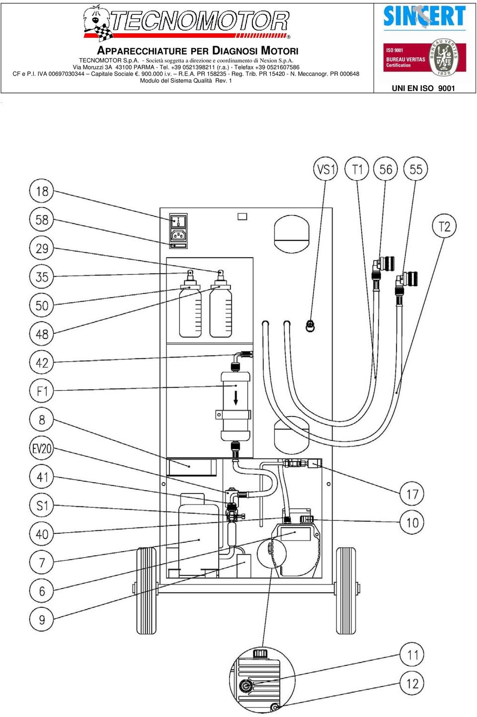
15 15. AC930 STATION LEGEND. EV1 Solenoid valve on the oil drain line EV2 Solenoid valve on the recovery line (steam phase) EV4 Solenoid valve on the vacuum pump intake line EV13 Solenoid valve on the refrigerant load line EV20 Solenoid valve on the oil return line to the compressor EV19 Solenoid valve on the oil load line 6 Vacuum pump 7 Compressor 31 Cylinder 43 Separator distiller 48 Oil drain container 50 Dispenser for oil or additives R14 Cylinder heater with thermostat TR15 Pressure transducer DS16 Separator float DS17 Security pressure switch CEL1 Refrigerant scale CEL2 Oil drain scale CEL3 Oil load scale V1 Low pressure hose valve V2 High pressure hose valve V6 Cylinder steam valve V8 Cylinder fluid valve V10 Manual distiller outlet valve S1 Service joint for the compressor evacuation S2 Cylinder fluid joint T1 Low pressure hose T2 High pressure hose CV1 Check valve on the intake line (recovery) CV2 Check valve on the compressor inlet line CV3 Check valve on the refrigerant load line CV4 Check valve on the oil drain line CV5 Check valve on the oil load line CV6 Check valve on the compressor outlet line (before the cylinder) F1 Drier filter VS1 Cylinder security valve M1 Low pressure manometer LOW Valve on the low pressure line M2 High pressure manometer HIGH Valve on the high pressure line 15

16 16. PWR MICROPROCESSOR BOARD LAYOUT. 16

17 17. PWR MICROPROCESSOR BOARD LEGEND. Connector Name Description BIL1 CEL1 Load cell 100 kg (refrigerant) BIL2 CEL2 Load cell 5 kg (exhausted oil drain) BIL4 CEL3 Load cell 5 kg (oil load) OUT4 CON8 EV1 Exhausted oil drain line solenoid valve OUT12 CON10 EV2 Recovery line solenoid valve OUT1 CON4 EV4 Vacuum line solenoid valve OUT2 CON6 EV13 Refrigerant load line solenoid valve OUT5 CON9 EV19 Oil load line solenoid valve OUT13A CON2 EV20 Oil return line to compressor solenoid valve 220VC CON3 PWR Board supply - 220V 12VDC CON19 - Board supply - 12V OUT3 CON5 R14 Resistance with thermostat on the cylinder PRES1 DS15 Pressure sensor OUT1 CON4 6 Vacuum pump OUT13B CON7 7-8 Compressor Motor fan SW1 CON11 DS16 Separator float SW2 CON17 DS17 Security pressure switch LS14 - Buzzer LCD - CN1 - LCD connector USB - USB port cable connector KEYBOARD - Dashboard PRINTER - Printer (optional) 17

18 18. AC930 STATION LAYOUT. 18

19 19
20 20

21 21
22 19. SPARE PARTS LIST. Description Code Position LOW PRESSURE MANOMETER M1 HIGH PRESSURE MANOMETER M2 SOLENOID VALVE ( ) 10 Bars EV1,EV2,EV4,EV13,EV19 SOLENOID VALVE ( ) 20 Bars EV20 CHECK VALVE ( ) CV1 CV6 LOAD CELL 100 kg ( ) CEL1 LOAD CELL 5 kg ( ) CEL2 CEL3 DRIER FILTER ( ) F1 COMPRESSOR ( ) M HIGH PRESSURE HOSE ( ) T2 3M LOW PRESSURE HOSE ( ) T1 HIGH PRESSURE QUICK COUPLING LOW PRESSURE QUICK COUPLING GUARD 58X81X49 ( ) AC930 BOARD PWR PRESSURE SENSOR TR15 FREON CYLINDER JOINT KIT ¼ SAE FREON CYLINDER RED ¼ SAE HIGH PRESSURE QUICK COUPLING VACUUM PUMP PANEL PRINTER MINIPLUS PRT REAR WHEEL (diameter 200 mm) CYLINDER EMPTYING KIT WEIGHT SAMPLE for CALIBRATION OIL CANS KIT
23 20. TROUBLESHOOTING. a. The Station does not turn on. Check the fuse placed under the on/off switch. b. The Station does not finish the recharge. Check that the cocks are open and that there are no obstructions into the hoses. Check for the correct position of the cocks on the Refrigerant Cylinder. Check that the resistor of the Refrigerant Cylinder is hot during the recharge phase. Check that the vacuum cycle is completely carried out and that there are no leaks on the vehicle. The vehicle circuit must be at 1Bar at the end of the vacuum cycle. c. The Station does not perform the Recovery. Check that the cocks are open and that there are no obstructions into the hoses. Check the Compressor operation. Check the correct Pressure Sensor calibration. d. The Station does not perform the Recovery cycle. Check the correct Vacuum Pump operation. Check the correct Pressure Sensor calibration. e. The Station does not introduce the new oil quantity into the vehicle correctly. Check that the Bottle air hose is not jammed. Check the New Oil Scale correct calibration (in this case, check the Exhausted Oil Scale too). f. The Station stops during the Recovery phase: Pressure too high. Check the correct Over Pressure Sensor operation. Replace the Microprocessor Board. g. The Station update through the USB port does not end correctly. Check that the USB support connected to the port is FAT32 formatted and that there is the installation file only. Replace the Microprocessor Board. h. The Station does not print with Printer. Check the Parameters. Check the printer cable correct connection. Replace the Printer. i. The Station display does not visualise correctly the software pages. Check that the Display flat cable does not have interferences touching the solenoid valves cables. Try to move the flat cable into a different position and check if the problem occurs again. j. The Station displays the "refrigerant missing" message. Fill in the refrigerant cylinder with a 2000gr minimum quantity of refrigerant (the recommended quantity is of 3000gr). 23
Replacement of hose carrier chain
 3 1. Bring the boom in horizontal position and make the extension completely retract. 2. Remove the rear panel. 3. Remove the front guard on the boom hood. 4. In case of machine with basket pre-arrangement,
P/N DESCRIPTION QUANTITY
 BEFORE STARTING WORKING, PLEASE MAKE SURE THAT YOU GOT ALL THE BELOW COMPONENTS OLD PUMP NUMBER BHD2226 NEW PUMP BHD2238 AQND KIT DRE2570 CHECK S/N IT S IMPORTANT P/N DESCRIPTION QUANTITY BHD2238 or BHD2239
Linea Aria Condizionata A/C System. Freon 134A Freon 1234Yf
 Linea Aria Condizionata A/C System Freon 134A Freon 1234Yf 627 Plus La Stazione 627 Plus è completamente automatica nelle funzioni di Recupero Scarico Olio Esausto Vuoto Immissione Olio nuovo Immissione
Installazione interfaccia e software di controllo mediante PC Installing the PC communication interface and control software
 Windows 7 Installazione interfaccia e software di controllo mediante PC Installing the PC communication interface and control software Contenuto del kit cod. 20046946: - Interfaccia PC-scheda (comprensiva
SRT064 BTH SRT051 BTH SRT052 BTH
 KIT FOR TRUCK BRAKE TESTERS SRT051 BTH SRT052 BTH OPERATOR S MANUAL SRT064BTH SRT051BTH SRT052BTH CONTENTS 1. INTRODUCTION...1 2. Description of SRT064BTH Kit...2 3. Description of SRT051BTH Kit...2 4.
Mod. 1067 INTERFACCIA USB/KEY USB/KEY INTERFACE. Sch./Ref.1067/003
 Mod. 1067 DS1067-019 LBT8388 INTERFACCIA USB/KEY USB/KEY INTERFACE Sch./Ref.1067/003 ITALIANO DESCRIZIONE GENERALE L interfaccia 1067/003 consente di collegare alla Centrale 1067/032 o 1067/042 (ver. 2.00
SOMMARIO GENERALITÀ 3 AGGIORNAMENTO FIRMWARE 4 PROGRAMMAZIONE DEL MICROPROCESSORE 7 AGGIORNAMENTO MULTICOM 302 / 352 4 AGGIORNAMENTO MULTI I/O 5
 MultiCOM - Mult lti I/O - Remote Panel - Istruzioni aggiornamento firmware - - Firmware upgrade instructions - SOMMARIO GENERALITÀ 3 AGGIORNAMENTO FIRMWARE 4 AGGIORNAMENTO MULTICOM 301 / 351 4 AGGIORNAMENTO
COME SI CONSULTA IL CATALOGO RICAMBI HOW TO READ THE SPARE PARTS CATALOGUE
 MAIN 24 Fi 24 i SPARE PARTS CATALOGUE - COME SI CONSULTA IL CATALOGO RICAMBI Dopo le tavole esplosi caldaie si trovano le liste dei componenti delle caldaie, suddivise in varie colonne, con il seguente
User Guide Guglielmo SmartClient
 User Guide Guglielmo SmartClient User Guide - Guglielmo SmartClient Version: 1.0 Guglielmo All rights reserved. All trademarks and logos referenced herein belong to their respective companies. -2- 1. Introduction
Multiconn Srl Pag. 1 DAS SW Upgrade rev.1
 HD Multiconn Srl Pag. 1 DAS SW Upgrade rev.1 Multiconn Srl Pag. 2 DAS SW Upgrade rev.1 Indice/Index Italiano pag.5 DASM44-CI // M44-CI-B // M44HD-R // M44HD-R-A // colore BLU DASM32 // M44 // M32-CI //
Scheda CPU Logika OKIR 510B Irinox cod. 3600160
 Connessione per pannello frontale cod. 300 o 3000 Connector for Front panel Board cod. 300 or 3000 Comune 4 Volt / Common 4 Volt Libero / free Clikson ventilatori / fan clikson Pressostato / pressure switch
REGISTRATION GUIDE TO RESHELL SOFTWARE
 REGISTRATION GUIDE TO RESHELL SOFTWARE INDEX: 1. GENERAL INFORMATION 2. REGISTRATION GUIDE 1. GENERAL INFORMATION This guide contains the correct procedure for entering the software page http://software.roenest.com/
Guida utente User Manual made in Italy Rev0
 Guida utente User Manual Rev0 made in Italy Indice/Index Informazioni generali General Info... 3 Guida Rapida per messa in funzione Start Up procedure... 3 Login Login... 3 Significato dei tasti Botton
Gateway Bacnet Multichiller series
 Servizio egolazione e Controllo File Pagina 1/11 Gateway Bacnet Multichiller series Servizio egolazione e Controllo File Pagina 2/11 CONTENTS 1. PCOWEB INSTALLATION... 3 2. BACNET MAPPING... 5 3. PCO COMMUNICATION
LEGEND UPDATE GUIDE INSTALLING LEGEND UPDATE. viscount. Legend Update Guide
 LEGEND UPDATE GUIDE INSTALLING LEGEND UPDATE The Legend series firmware is upgradable via PC. You must first download the Legend Update application from http://www.instruments.com. NB Legend Update is
MANUALE DISPLAY REMOTO CALDAIE REMOTE DISPLAY MANUAL FOR BOILERS
 MANUALE DISPLAY REMOTO CALDAIE REMOTE DISPLAY MANUAL FOR BOILERS COMPATIBILE CON - COMPATIBLE WITH LP14/20/30 SCHEDA - MOTHERBOARD 512 E SW V5 2 IT COLLEGAMENTO A MURO DELLA CONSOLE LCD - CALDAIA Collegamento
AC490PRO - AC590PRO - AC690PRO
 AC490PRO - AC590PRO - AC690PRO Recovery-Recycling-Recharging A/C Service Stations ITA PROGRAMMA DI LAVAGGIO INTEGRATO INTEGRATED FLUSHING KIT PROGRAM ENG DP0153 BANCA DATI INTEGRATA AGGIORNABILE INTEGRATED
Centrale MK3 MK3 power packs
 Centrale power packs Manuale di regolazione Adjusting manual - Installare la centrale sulla rampa e collegare i raccordi idraulici A e B come nell immagine sottostante. - Instal the power pack on the dock
CONFIGURATION MANUAL
 RELAY PROTOCOL CONFIGURATION TYPE CONFIGURATION MANUAL Copyright 2010 Data 18.06.2013 Rev. 1 Pag. 1 of 15 1. ENG General connection information for the IEC 61850 board 3 2. ENG Steps to retrieve and connect
3G HSPA USB MULTIMODEM High Speed Wireless Connectivity MT4211
 3G HSPA USB MULTIMODEM High Speed Wireless Connectivity MT4211 Instructions Manual Introduction Thank you for your purchasing our HSUPA USB modem with TF fl ash card socket. Device is backward compatible
DICHIARAZIONE DI RESPONSABILITÀ
 - 0MNSWK0082LUA - - ITALIANO - DICHIARAZIONE DI RESPONSABILITÀ Il produttore non accetta responsabilità per la perdita di dati, produttività, dispositivi o qualunque altro danno o costo associato (diretto
BVBA POMAC-LUB-SERVICES SPRLKorte Bruggestraat 28 B-8970 Poperinge Tel. 057/33 48 36 Fax 057/33 61 27 info@pomac.be internet: www.pomac.
 BVBA POMAC-LUB-SERVICES SPRLKorte Bruggestraat 28 B-8970 Poperinge UNITA LUBETOOL MC-EL-3P-4P-5P-6P-7P, MC-EL-3M-4M-5M-6M-7M, MC-EL-2P E MC- EL-2M Sono forniti completi di scatola di protezione metallica
Prefiltri Prefilter ISTRUZIONI PER L USO OPERATING INSTRUCTIONS
 Prefiltri Prefilter PF ISTRUZIONI PER L USO OPERATING INSTRUCTIONS 1.Componenti 1.Components DESCRIZIONE DESCRIPTION 1 Semi guscio inferiore Bottom spherical shell flange 2 Cestello Basket 3 Guarnizione
UNIVERSITÀ DEGLI STUDI DI TORINO
 STEP BY STEP INSTRUCTIONS FOR COMPLETING THE ONLINE APPLICATION FORM Enter the Unito homepage www.unito.it and click on Login on the right side of the page. - Tel. +39 011 6704425 - e-mail internationalexchange@unito.it
599CD/A I EN ISTRUZIONI PER L USO INSTRUCTIONS FOR USE
 599CD/A I EN ISTRUZIONI PER L USO INSTRUCTIONS FOR USE ISTRUZIONI PER L USO I Installazione del software Inserire il CD di installazione nel CD-ROM. Nella directory principale del CD cliccare setup.exe
POWERGATE-S USER GUIDE
 POWERGATE-S USER GUIDE 1 POWERGATE-S USER GUIDE Introduzione Powergate-S Il più efficace tool per potenziare le qualità del tuo veicolo, attraverso la presa OBDII è in grado di programmare la nuova mappatura
Gateway Bacnet Multichiller series
 Servizio egolazione e Controllo File Pagina 1/12 Gateway Bacnet Multichiller series Servizio egolazione e Controllo File Pagina 2/12 CONTENTS 1. PCOWEB INSTALLATION... 3 2. BACNET MAPPING... 5 3. PCO COMMUNICATION
PUMP CONTROLLER PUMP ACTIVE CONTROLLER
 PUMP CONTROLLER PUMP ACTIVE CONTROLLER Technical catalogue Catalogo tecnico rev. 0 del 22/09/2017 PUMP CONTROLLER PUMP ACTIVE CONTROLLER WARNINGS AND LIMITATIONS ON USE The Pump Controller/ Pump Active
Quick start manual Manuale rapido. Version 3.0
 Quick start manual Manuale rapido Version 3.0 1 Scope of delivery Contenuto della fornitura CITREX Mini USB cable, power cable Cavo di alimentazione Mini USB Plug-in power supply Alimentatore per rete
Manuale Handbook. Via Torino 16-15020 Piagera di Gabiano (AL) - ITALIA Tel.+ 39 0142 xxxxxx - fax +39 xxxxx. E-mail: support.race@dimsport.
 - ITALIA Tel.+ 39 0142 xxxxxx - fax +39 xxxxx. E-mail: support.race@dimsport.") DIMA 555PRO Manuale Handbook Via Torino 16-15020 Piagera di Gabiano (AL) - ITALIA Tel.+ 39 0142 xxxxxx - fax +39 xxxxx E-mail: supporto.race@dimsport.it E-mail: support.race@dimsport.it http://www.dimsport.it
DIMA 555PRO Manuale Handbook Via Torino 16-15020 Piagera di Gabiano (AL) - ITALIA Tel.+ 39 0142 xxxxxx - fax +39 xxxxx E-mail: supporto.race@dimsport.it E-mail: support.race@dimsport.it http://www.dimsport.it
Downloading and Installing Software Socio TIS
 Object: Downloading and Installing Software Socio TIS compiler: L.D. Date Revision Note April 17 th 2013 --- For SO XP; Win 7 / Vista step Operation: Image A1 Open RUN by clicking the Start button, and
MANUALE D USO E MANUTENZIONE MAINTENANCE AND OPERATING MANUAL ZERO DRAIN
 OMI srl MANUALE D USO E MANUTENZIONE MAINTENANCE AND OPERATING MANUAL ZERO DRAIN Costruito in accordo alle Direttive 2006/95/CE, 2004/108/CE Manufactured accordingly to European Directives 2006/95/CE,
User Manual. Rev Date: 31/05/2018
 Size / Misure 8 50 500 60 150 POWER IN DMX IN DMX OUT 9 4. POWER+DMX out cable + M8 Female Connector 16,80 Connection kit included with the Startline cable / Kit di connessione compreso alla startline
NEWS 68. Valves and Solenoid valves Poppet system N776 Series
 NEWS 68 Components for pneumatic automation Valves and Solenoid valves Poppet system N776 Series www.pneumaxspa.com Valves and solenoid valves Poppet system 2/2-3/2 for compressed air and Vacuum - G1 1/2"
ISTRUZIONE DI SERVIZIO SERVICE INSTRUCTION
 ISTRUZIONE DI SERVIZIO SERVICE INSTRUCTION Procedura sostituzione motore tipo VALEO 404 864 rotazione braccio ROTOGRAPH PLUS Replacing the arm rotation motor type VALEO 404 864 on the ROTOGRAPH PLUS NOTA:
HS RC-BW06V. Kit Content. AUX Video input cable LVDS Video cable
 Connettore LCD HS RC-BW06V BMW 1 Series (E81) - 3 Series (E90) - 5 Series (E60) 6 Series (E63) - 7 Series (F01,F02) X5 E70) - X6 (E71) - 2004-2008 INTERFACCIA RETROCAMERA INGRESSI AUDIO VIDEO PREDISPOSIZIONE
WELCOME. Go to the link of the official University of Palermo web site www.unipa.it; Click on the box on the right side Login unico
 WELCOME This is a Step by Step Guide that will help you to register as an Exchange for study student to the University of Palermo. Please, read carefully this guide and prepare all required data and documents.
MANUALE DI ISTRUZIONI MOVIMENTO VD51 Cronografo con secondi e minuti
 MANUALE DI ISTRUZIONI MOVIMENTO VD51 Cronografo con secondi e minuti FUNZIONAMENTO VD51 DISPLAY E PULSANTI DELLA CORONA Lancetta minuti Lancetta ore Lancetta secondi Lancetta minuti cronometro Lancetta
Aggiornamento dispositivo di firma digitale
 Aggiornamento dispositivo di firma digitale Updating digital signature device Questo documento ha il compito di descrivere, passo per passo, il processo di aggiornamento manuale del dispositivo di firma
quick guide guida rapida J.touch hydromassage bath remote control telecomando per vasche idromassaggio
 quick guide guida rapida hydromassage bath remote control telecomando per vasche idromassaggio getting started operazioni preliminari 3 4 5 switch on the remote control by holding the on/off key; turn
ACCESSORIO RICIRCOLO SANITARIO ELETTRONICO
 ACCESSORIO RICIRCOLO SANITARIO ELETTRONICO DESCRIZIONE Il KIT di ricircolo per il modulo ACS 40 E viene fornito separatamente dal modulo, è composto da un circolatore, valvola a sfera /4 M, valvola di
KC5H Cod. K per martelli installabili su escavatori da 5 a 30 tonnellate for hammers to be mounted on excavators from 5 to 30 tons
 KC5H Cod. K8100000 per martelli installabili su escavatori da 5 a 30 tonnellate for hammers to be mounted on excavators from 5 to 30 tons Specifiche / Specification Pressione in uscita OutPut Pressure
SISTEMA AUTOMATICO PER CAMBIO OLIO AUTOMATIC SYSTEM FOR OIL CHANGE
 SISTEMA AUTOMATICO PER CAMBIO OLIO AUTOMATIC SYSTEM FOR OIL CHANGE AVVERTENZE D USO INSTRUCTIONS FOR USE 12V / 24V 12V / 24V 12V / 24V 12V / 24V 110V / 220V 11/02/19 Rev.04 164 924 15 - OCS3/E 164 925
Istruzioni di montaggio per ECOFLEX KIT Assembling Instructions for ECOFLEX KIT
 Page 1/7 Release 2 ECOFLEX Kit Istruzioni di montaggio per ECOFLEX KIT Assembling Instructions for ECOFLEX KIT Prima di effettuare le varie operazioni procedere nel modo seguente: - Portare la macchina
TABELLA DI IDENTIFICAZIONE CODICI POMPE HWD A 1515 B 1818 A B 2121 A B 2525 A B 1821 A B
 TAELLA DI IDENTIFICAZIONE CODICI POMPE -88-22-2525-82 A 55 88 A 22 A 2525 A 82 A Modello Materiale testata 55. 88. 22. 2525. 82. A Con manometro 400 bar Senza manometro Ottone Material del corpo Materiale
Code: GW-IMP-WEB-1. Datalogger web pulses counter. Version 6 inputs with Ethernet. MarCom
 Datalogger web pulses counter Code: GW-IMP-WEB-1 Version 6 inputs with Ethernet Datalogger web pulses counter The web datalogger pulses counter is able to count the pulses on digital inputs (2 by default
SCHEMI DI MONTAGGIO ASSEMBLY DIAGRAM
 SCHEMI DI MONTAGGIO ASSEMBLY DIAGRAM Ver. 3.2 ISGI008 BIGAS INTERNATIONAL AUTOGAS SYSTEMS S.r.l. Sede e Stabilimento: Via di Le Prata, 62/66 50041 Calenzano Firenze ITALY Tel. 0554211275-0554201432 Fax
MANUALE DI ISTRUZIONI PER L INSTALLAZIONE, L USO E LA MANUTENZIONE DI: OVERHAUL HANDBOOK FOR INSTALLATION, USE AND MAINTENANCE OF:
 Sede Operativa: 27020 PARONA (PV) Italy Via Artigianato, 12 Tel. +39 0384 253136 Fax +39 0384 253574 E-mail:info@azzalinsrl.it Web site: www.azzalinsrl.it Sede Legale: 27026 GARLASCO (PV) Vicolo della
CCTV DIVISION. Guida Alla Lettura del Numero Seriale, Codice Prodotto, Versione Firmware, Versione Software, Codice Libretto
 CCTV DIVISION Guida Alla Lettura del Numero Seriale, Codice Prodotto, Versione Firmware, Versione Software, Codice Libretto How to Get Serial Number, Firmware Version, Product Code, Software Version, User
COSMO. Screwdriving System equipped with Electronic Torque Control
 COSMO Screwdriving System equipped with Electronic Torque Control ELECTRONIC CONTROL UNIT COSMO 100 The new COSMO 100 electronic control unit is able to operate according to 7 screwing methods: 1. SIMPLE
D D S Application Example
 MAD E IN ITALY DDS889 è un kit di due moduli elettronici sviluppati per lampade alimentate a batterie, questo kit prevede un modulo da installare nella l lampada portatile, ed un modulo come base per la
Portale Materiali Grafiche Tamburini. Grafiche Tamburini Materials Portal
 Portale Materiali Grafiche Tamburini Documentazione utente italiano pag. 2 Grafiche Tamburini Materials Portal English user guide page 6 pag. 1 Introduzione Il Portale Materiali è il Sistema Web di Grafiche
MACCHINE DA CAFFE' AUTOMATICA AUTOMATIC COFFEE MACHINES
 MACCHINE DA CAFFE' AUTOMATICA AUTOMATIC COFFEE MACHINES DE' LONGHI ECAM 23.450 EX: 3 (INT-AU/NZ-RU-SKA-CH) DATI TECNICI / TECHNICAL DATA / TECHNISCHE DATEN DONNEES TECHNIQUES / DATOS TECNICOS Voltaggio
SISTEMA DI ILLUMINAZIONE PER VERRICELLI WINDLASS LIGHTING SYSTEM
 Istruzioni per l uso Instructions for use SISTEMA DI ILLUMINAZIONE PER VERRICELLI WINDLASS LIGHTING SYSTEM WLS WINDLASS LIGHTING SYSTEM - 1 - Rev.01-2013 Italiano SISTEMA DI ILLUMINAZIONE PER VERRICELLI
How to use the WPA2 encrypted connection
 How to use the WPA2 encrypted connection At every Alohawifi hotspot you can use the WPA2 Enterprise encrypted connection (the highest security standard for wireless networks nowadays available) simply
POMPA PNEUMOIDRAULICA PNEUMOHYDRAULIC PUMP VERSIONE PER OLIO E PER ACQUA OIL AND WATER WORKING APPLICATION
 POMPA PNEUMOIDRAULICA PNEUMOHYDRAULIC PUMP VERSIONE PER OLIO E PER ACQUA OIL AND WATER WORKING APPLICATION VERSIONE MANUALE CON VOLANTINO MANUAL VERSION WITH HANDWHEEL VERSIONE CON COMANDO PNEUMATICO A
TLR05S-350. Extender in corrente costante, 3 x 350mA per TLR04M_
 TLR05S-350 Extender in corrente costante, 3 x 350mA per TLR04M_350-500 IT DATI TECNICI Alimentazione Uscita Tipo di carico Sistema di collegamento master/slave/slave Distanza massima delle connessioni
Sistemi di vuoto, carica e recupero Vacuum, charging and recovery units
 7 Stazione di vuoto e carica in valigetta 8 Vacuum and charging system with case Unità di recupero 9 Recovery unit Unità di recupero con separatore di traccianti ed olii 9 Recovery unit with oil separator
EN IT. Computer Manual. Manuale computer. Console
 Computer Manual Manuale computer EN IT Console www.energetics.eu Table of contents / Indice 1. English....................................... p. 4 2. Italiano....................................... p.
MODULO IDRAULICO DI INTEGRAZIONE E ACS
 MODULO IDRAULICO DI INTEGRAZIONE E ACS Hot sanitary water production and integration hydraulic module Accessori pompe di calore INSTALLAZIONE E USO Installation and use I Il presente documento è da considerarsi
CAP 4 Elettrovalvole e valvole pneumatiche Solenoid and pneumatic valves
 CAP 4 Elettrovalvole e valvole pneumatiche Solenoid and pneumatic valves 4.0 mm Manifold and single elettrovalvola /-/vie G/ solenoid valve /-/ways G/ comando elettropneumatico diretto riposizionamento
Compatibilità del Portale Piaggio con Internet Explorer 10 e 11. Internet Explorer 10
 Italiano: Explorer 10 pagina 1, Explorer 11 pagina 2 English: Explorer 10 page 3 and 4, Explorer 11 page 5. Compatibilità del Portale Piaggio con Internet Explorer 10 e 11 Internet Explorer 10 Con l introduzione
DEVIATORI DI FLUSSO DIVERTER VALVES
 DEVIORI DI FLUSSO DIVERER VLVES OLEODINMIC MRCHESINI.1 - DEVIORI DI FLUSSO 3 VIE.1-3-WYS DIVERER VLVES tipo/ type DF 3 Schema Idraulico (con centro aperto) Hydraulic Diagram (with opened centre) richiesta
Manuale utente - User manual. 6 CH. LED Control
 Manuale utente - User manual ATTENZIONE: Prima di usare questi apparecchi, leggere attentamente le istruzioni che seguono. Spotlight srl non potrà essere ritenuta responsabile di danni derivanti dalla
ATTENZIONE! / WARNING! Scollegare le batterie prima di qualsiasi operazione! Disconnect batteries before servicing! Kit caricabatteria :
 Page 1 / 8 Release INSTALLATION INSTRUCTIONS PROCEDURA D INSTALLAZIONE 1 3 ATTENZIONE! / WARNING! Scollegare le batterie prima di qualsiasi operazione! Disconnect batteries before servicing! Kit caricabatteria
Istruzioni per lo smontaggio delle Lancette; smontaggio quadrante e la regolazione della lancetta dei minuti.
 Istruzioni per lo smontaggio delle Lancette; smontaggio quadrante e la regolazione della lancetta dei minuti. Instructions to remove hands, remove dial and adjust the minute hand. 2 I. Removing hands.
lubrificatore G1/4 LUB 2-00 G1/4 lubricator
 lubrificatore G1/4 G1/4 lubricator Lubrificatore venturi con compensazione automatica della portata Oil mist lubricator with flow compensation Il numero di gocce al minuto è costante Number of drops per
TNCguide OEM Informativa sull introduzione di documentazione aggiuntiva nella TNCguide
 Newsletter Application 4/2007 OEM Informativa sull introduzione di documentazione aggiuntiva nella APPLICABILITÀ: CONTROLLO NUMERICO itnc 530 DA VERSIONE SOFTWARE 340 49x-03 REQUISITI HARDWARE: MC 420
Corso Tecnico T chn h i n c i al Tr T ain i i n n i g n g Im I x
 Technical Training Imx Dimensions My 50 MMx 50 Corso Tecnico Dimensions 103 cm 51cm 118 cm 68 cm Techincal Data Technical Data imx 50B imx 50BT imx 50BB Autonomy up to (h) 2 2 2 Width with squeegee (mm)
Interface A25 (+90 ) Interfaccia A25 (+90 ) O-RING #109 O-RING #109 O-RING #010 O-RING #109
 Interfaccia A25 (+90 ) O-RING #109 O-RING #109 O-RING #010 O-RING #109") Accessori Gimapick Gimapick Accessories A25 Interfaccia A25 (+90 ) L interfaccia A25 è necessaria quando l asse di rotazione e/o di presa debba essere posto a 90 rispetto all asse di traslazione o rispetto
Accessori Gimapick Gimapick Accessories A25 Interfaccia A25 (+90 ) L interfaccia A25 è necessaria quando l asse di rotazione e/o di presa debba essere posto a 90 rispetto all asse di traslazione o rispetto
CEDMEGA Rev 1.2 CONNECTION TUTORIAL
 CEDMEGA Rev 1.2 CONNECTION TUTORIAL rev. 1.0 19/11/2015 1 www.cedelettronica.com Indice Power supply [Alimentazione]... 3 Programming [Programmazione]... 5 SD card insertion [Inserimento SD card]... 7
IF2E001 Interfaccia Ethernet-RS485
 IF2E001 Interfaccia Ethernet-RS485 Manuale utente File : Ethernet interfaccia-manuale utente.doc 1/4 Interfaccia Ethernet manuale utente Versione 1.1 1 DESCRIZIONE GENERALE Questo dispositivo consente
You can visualize the free space percentage in Compact Flash memory from the MENU/INFO C.F. UTILITY-FREE SPACE page.
 This release introduces some new features: -TUNE PITCH -FREE SPACE -TUNER -DRUMKIT EDITOR From the PARAM MIDI page, it is possible to modify the "TUNE PITCH" parameter, which allows you to tune up the
DP 2010 E depressore diretto G1/8 direct vacuum generator with G1/8 port
 DP 2010 E - 03.020.4 depressore diretto G1/8 direct vacuum generator with G1/8 port m / 100 pressione di alimentazione [] pressure supply [] vuoto massimo [] maximum 0.27 0.42 0.58 0.64 0.68 0.7 0.72 0.72
INSTALLARE PALLADIO USB DATA CABLE IN WINDOWS XP/ME/2000/98
 rev. 1.0-02/2002 Palladio USB Data Cable INSTALLARE PALLADIO USB DATA CABLE IN WINDOWS XP/ME/2000/98 (tutti i KIT, escluso KIT MOTOROLA V6x-T280) La procedura di installazione del Palladio USB Data Cable
ISTRUZIONI DI USO E MANUTENZIONE INSTALLATION AND USE
 VENUS FAMILY ISTRUZIONI DI USO E MANUTENZIONE INSTALLATION AND USE ITALIANO MESSA IN FUNZIONE 1.Montare sulla cupola l aquila che si trova nella scatola accessori. 2.Alzare la cupola e riempire con acqua
 MANUALE UTENTE MODULO ESPANSIONE TASTI MANUALE UTENTE MANUALE UTENTE Descrizione Il modulo fornisce al telefono VOIspeed V-605 flessibilità e adattabilità, mediante l aggiunta di trenta tasti memoria facilmente
Guida all installazione del prodotto 4600 in configurazione plip
 Guida all installazione del prodotto 4600 in configurazione plip Premessa Questo prodotto è stato pensato e progettato, per poter essere installato, sia sulle vetture provviste di piattaforma CAN che su
OWNER MANUAL USO E MANUTENZIONE OMNILINK CONTROL PANEL QUADRO DI COMANDO OMNILINK
 OWNER MANUAL USO E MANUTENZIONE OMNILINK CONTROL PANEL QUADRO DI COMANDO OMNILINK TRANSLATED FROM THE ORIGINAL MANUAL IN ITALIAN LANGUAGE. Data reported in this issue can be modified at any time by Lombardini
PLC2 ELECTRONIC BOARD SCHEDA ELETTRONICA PLC2
 APPLICATION NOTES NOTE DI APPLICAZIONE January 005 Gennaio 005 PLC ELECTRONIC BOARD SCHEDA ELETTRONICA PLC g TeKne Dental s.r.l. Via del Pescinale 77-50041 Calenzano (FI) - ITALY info@teknedental.com www.teknedental.com
How to connect SL Controllers to your computer
 How to connect SL Controllers to your computer Follow these instructions to enable the best connection between the SL Controller and your computer. 1 3 2 1. Connect the instrument to an electrical outlet
Sez./Section R Valvole per escavatori idraulici Hydraulic excavator Valves
 Sez./Section R Valvole per escavatori idraulici Hydraulic excavator Valves Valvole overcenter per escavatori Sono valvole overcenter specifiche per il controllo della discesa e sospensione dei bracci degli
ELCART. Manuale di istruzioni/scheda tecnica SPECIFICATION
 PAGINA 1 DI 7 SPECIFICATION Customer : ELCART Applied To : Product Name : Piezo Buzzer Model Name : : Compliance with ROHS PAGINA 2 DI 7 2/7 CONTENTS 1. Scope 2. General 3. Maximum Rating 4. Electrical
CAMBIO OLIO TRIAL LATO DESTRO TRIAL OIL CHANGE RIGHT SIDE
 CAMBIO OLIO TRIAL LATO DESTRO TRIAL OIL CHANGE RIGHT SIDE La tabella sottostante indica gli intervalli di cambio olio consigliati. La sostituzione di olio con intervallo di tempo troppo lungo, portano
QUASAR WESTEN SPARE PARTS CATALOGUE - MARCH
 QUASAR WESTEN COME SI CONSULTA IL CATALOGO RICAMBI Dopo le tavole esplosi caldaie si trovano le liste dei componenti delle caldaie, suddivise in varie colonne, con il seguente significato: Pos. Descrizione
sdforexcontest2009 Tool
 sdforexcontest2009 Tool Guida all istallazione e rimozione. Per scaricare il tool del campionato occorre visitare il sito dell organizzatore http://www.sdstudiodainesi.com e selezionare il link ForexContest
Scheda Allarmi Alarm Board MiniHi
 Scheda Allarmi Alarm Board MiniHi Manuale Utente User Manual Italiano English cod. 272680 - rev. 18/04/02 ITALIANO INDIE 1. INTRODUZIONE...2 2. RIONOSIMENTO DEI LIVELLI DI TENSIONE DEL SEGNALE 0-10 VOLT...2
MILLIOHM METER PORTATILE 1 MANUALE UTENTE 62000880 PROFESSIONAL ELECTRONIC INSTRUMENTS MILLIOHM - METER
 MILLIOHM METER PORTATILE 1 PROFESSIONAL ELECTRONIC INSTRUMENTS MILLIOHM - METER MILLIOHM METER PORTATILE 2 1 Descrizione generale / General description. 3 2 Caratteristiche tecniche/technical Features.
Valvole / Valves 36 68
 Valvole / Valves 36 Valvole manuali ad angolo per alto vuoto Le valvole ad angolo sono realizzate con flange normalizzate Pneurop - ISO 16-25-40-50-63-100. I componenti a contatto con il vuoto sono in
IM-IU v0.1. alternata e continua. pag. 1 / 5
 MANUALE OPERATIVO IM-IU v0.1 INSTRUCTION MANUAL SERIE TTC-V-485 Trasformatore di corrente alternata e continua PROTOCOLLO DI COMUNICAZIONE MODBUS TTC-V-485 SERIES AC/DC current transformer MODBUS COMMUNICATION
SISTEMA COMPLETO DI ILLUMINAZIONE VANO LAMPADA A LED TIPO ILV24 s. COMPARTMENT SYSTEM LIGHTING COMPLETE LED LAMP TYPE ILV24 s
 SISTEMA COMPLETO DI ILLUMINAZIONE VANO LAMPADA A LED TIPO ILV24 s COMPARTMENT SYSTEM LIGHTING COMPLETE LED LAMP TYPE ILV24 s Caratteristiche generali Mean features Lampade a bassa tensione (24Vcc) Lamps
SPIGOLATORE. Brembana CMS. Industries Tel. +39 0345 64 201 - Fax +39 0345 64 280. www.cms.it. glass technology
 www.cms.it ITA GB F D E CMS Industries 24019 Zogno (Bg) Italy - via A. Locatelli, 49 Tel. +39 0345 64 201 - Fax +39 0345 64 280 www.cms.it Manuale d Installazione Uso e Manutenzione Installation, Operating
MANUALE ISTRUZIONI INSTRUCTIONS MANUAL
 MANUALE ISTRUZIONI INSTRUCTIONS MANUAL V.2017.07 PSK-SDC ITALIANO ENGLISH 1 MANUALE ISTRUZIONI Questo manuale contiene una rapida guida alle funzioni principali della pompa PSK SDC. Al primo avvio suggeriamo
INSTALLAZIONE KIT DOSATORE DI DETERGENTE DETERGENT DISPENSER KIT INSTALLATION
 INSTALLAZIONE KIT DOSATORE DI DETERGENTE DETERGENT DISPENSER KIT INSTALLATION ATTENZIONE PERICOLO TUTTE LE OPERAZIONI DESCRITTE DI SEGUITO DEVONO ESSERE ESEGUITE DA PERSONALE QUALIFICATO E ADDESTRATO WARNING
electric lifting trolley Dimensioni 220 cm 42 (183) cm 72 cm Portata 175 kg Art. -CEAC041 Carrello elevatore Con rulli Altre VerSIONI OTHER VERSIONS
 cm 72 cm Portata 175 kg Art. -CEAC041 Carrello elevatore Con rulli Altre VerSIONI OTHER VERSIONS") Elevatore elettrico electric lifting trolley 175 kg Art. -CEAC041 Lifting trolley with rolls Il carrello elevatore elettrico viene utilizzato sia per il trasporto delle salme su barelle, sia in abbinamento
Elevatore elettrico electric lifting trolley 175 kg Art. -CEAC041 Lifting trolley with rolls Il carrello elevatore elettrico viene utilizzato sia per il trasporto delle salme su barelle, sia in abbinamento
SEZIONE VAPORE / STEAM SECTION
 M ACCHINA DA CAFFE' AUTOMATICA AUTOMATIC COFFEE MACHINES DE' ONGHI PRIMADONNA ESAM 6700 EX:1 (INT/CH/ATDE) DATI TECNICI / TECHNICA DATA / TECHNISCHE DATEN DONNEES TECHNIQUES / DATOS TECNICOS Voltaggio
INDICAZIONI GENERALI SULL'INSTALLAZIONE DEL BOILER
 INDICZIONI GENERLI SULL'INSTLLZIONE DEL BOILER Caratteristiche del tubi da utilizzare nell'impianto Idonei per acqua calda miscelata con antigelo Temperature di esercizio: - 40 + 0 C Diametro interno:
DIESEL& PETROL ENGINE ISTRUZIONI DI MONTAGGIO INSTALLATION MANUAL. CPBX STD rev
 P R O G R A M M A B L E DIESEL& PETROL C H I P T U N I N G U N I T ENGINE ISTRUZIONI DI MONTAGGIO INSTALLATION MANUAL CPBX STD rev 1.0 2018 06 AVVERTENZE / WARNINGS 1 LEGGI QUESTA GUIDA CON ATTENZIONE