E04 RIDUTTORI E MOTORIDUTTORI COASSIALI COXIAL GEAR REDUCERS AND GEARMOTORS. (normali e per traslazione) (standard and for traverse movements)
|
|
|
- Michele Garofalo
- 5 anni fa
- Visualizzazioni
Transcript


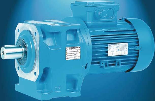
1 RIDUTTORI E MOTORIDUTTORI COASSIALI (normali e per traslazione) COXIAL GEAR REDUCERS AND GEARMOTORS (standard and for traverse movements) P 1 0, kw, M N dan m, i N , n 2 0, min -1 E04
2 Indice Index 1 - Simboli e unità di misura Caratteristiche Designazione Fattore di servizio fs Scelta Potenze e momenti torcenti nominali (riduttori) Esecuzioni, dimensioni, forme costruttive e quantità di lubrificante Programma di fabbricazione (motoriduttori) Programma di fabbricazione (motoriduttori per traslazione) Esecuzioni, dimensioni, forme costruttive e quantità di lubrificante Gruppi riduttori e motoriduttori Dimensioni gruppi Carichi radiali F r1 sull estremità d albero veloce Carichi radiali F r2 o assiali F a2 sull estremità d albero lento Dettagli costruttivi e funzionali Installazione e manutenzione Accessori ed esecuzioni speciali Formule tecniche Symbols and units of measure Specifications Designation Service factor fs Selection Nominal powers and torques (gear reducers) Designs, dimensions, mounting positions and lubricant quantities Manufacturing programme (gearmotors) Manufacturing programme (gearmotors for traverse movements) Designs, dimensions, mounting positions and lubricant quantities Combined gear reducer and gearmotor units Combined unit dimensions Radial loads F r1 on high speed shaft end Radial loads F r2 or axial loads F a2 on low speed shaft end Structural and operational details Installation and maintenance Accessories and non-standard designs Technical formulae 93

 Combined gear reducer and gearmotor units MR 3I + R 2I, 3I MR 3I + MR")
3 Riduttori e motoriduttori coassiali Coaxial gear reducers and gearmotors 2I, 3I * a 2, 3 ingranaggi cilindrici with 2, 3 cylindrical gear pairs 2I, 3I a 2, 3 ingranaggi cilindrici with 2, 3 cylindrical gear pairs Gruppi riduttori e motoriduttori (combinati) Combined gear reducer and gearmotor units MR 3I + R 2I, 3I MR 3I + MR 2I, 3I * solo motoriduttori * gearmotors only 3
4 1 - Simboli e unità di misura 1 - Symbols and units of measure Simboli in ordine alfabetico, con relative unità di misura, impiegati nel catalogo e nelle formule. Symbols used in the catalogue and formulae, in alphabetical order, with relevant units of measure. Simbolo Espressione Unità di misura Note Symbol Definition Units of measure Notes Nel catalogo Nelle formule In the In the formulae catalogue Sistema Tecnico Sistema SI 1) Technical System SI 1) System dimensioni, quote dimensions mm a accelerazione acceleration m/s 2 d diametro diameter m f frequenza frequency Hz Hz fs fattore di servizio service factor ft fattore termico thermal factor F forza force kgf N 2) 1 kgf 9,81 N 0,981 dan F r carico radiale radial load dan F a carico assiale axial load dan g accelerazione di gravità acceleration of gravity m/s 2 val. norm. 9,81 m/s 2 normal value 9,81 m/s 2 G peso (forza peso) weight (weight force) kgf N Gd 2 momento dinamico dynamic moment kgf m 2 i rapporto di trasmissione transmission ratio i = n 1 n 2 I corrente elettrica electric current A J momento d inerzia moment of inertia kg m 2 kg m 2 L h durata dei cuscinetti bearing life h m massa mass kg kgf s 2 /m kg 3) M momento torcente torque dan m kgf m N m 1 kgf m 9,81 N m 0,981 dan m n velocità angolare speed min -1 giri/min rev/min 1 min -1 0,105 rad/s P potenza power kw CV W 1 CV 736 W 0,736 kw Pt potenza termica thermal power kw r raggio radius m R rapporto di variazione variation ratio R = n 2 max n 2 min s spazio distance m t temperatura Celsius Celsius temperature C t tempo time s s min 1 min = 60 s h 1 h = 60 min = s d 1 d = 24 h = s U tensione elettrica voltage V V v velocità velocity m/s W lavoro, energia work, energy MJ kgf m J 4) z frequenza di avviamento frequency of starting avv./h starts/h accelerazione angolare angular acceleration rad/s 2 rendimento efficiency s rendimento statico static efficiency coefficiente di attrito friction coefficient angolo piano plane angle rad 1 giro = 2 rad 1 rev = 2 rad 1 = rad 180 velocità angolare angular velocity rad/s 1 rad/s 9,55 min -1 Indici aggiuntivi e altri segni Additional indexes and other signs Ind. Espressione Definition max massimo maximum min minimo minimum N nominale nominal 1 relativo all asse veloce (entrata) relating to high speed shaft (input) 2 relativo all asse lento (uscita) relating to low speed shaft (output) da... a from... to uguale a circa approximately equal to maggiore o uguale a greater than or equal to minore o uguale a less than or equal to 1) SI è la sigla del Sistema Internazionale di Unità, definito ed approvato dalla Conferenza Generale dei Pesi e Misure quale unico sistema di unità di misura. Ved. CNR UNI (DIN NF X , BS , ISO ). UNI: Ente Nazionale Italiano di Unificazione. DIN: Deutscher Normenausschuss (DNA). NF: Association Française de Normalisation (AFNOR). BS: British Standards Institution (BSI). ISO: International Organization for Standardization. 2) Il newton [N] è la forza che imprime a un corpo di massa 1 kg l accelerazione di 1 m/s 2. 3) Il kilogrammo [kg] è la massa del campione conservato a Sèvres (ovvero di 1 dm 3 di acqua distillata a 4 C). 4) Il joule [J] è il lavoro compiuto dalla forza di 1 N quando si sposta di 1 m. 1) SI are the initials of the International Unit System, defined and approved by the General Conference on Weights and Measures as the only system of units of measure. Ref. CNR UNI (DIN NF X , BS , ISO ). UNI: Ente Nazionale Italiano di Unificazione. DIN: Deutscher Normenausschuss (DNA). NF: Association Française de Normalisation (AFNOR). BS: British Standards Institution (BSI). ISO: International Organization for Standardization. 2) Newton [N] is the force imparting an acceleration of 1 m/s 2 to a mass of 1 kg. 3) Kilogramme [kg] is the mass of the prototype kept at Sèvres (i.e. 1 dm 3 of distilled water at 4 C). 4) Joule [J] is the work done when the point of application of a force of 1 N is displaced through a distance of 1 m. 4
5 2 - Caratteristiche 2 - Specifications Fissaggio universale (brevettato; piedi inferiori, piedi superiori, flangia B5 con estremità d albero lento spostata in avanti) Scalamento infittito delle grandezze (per le grandezze doppie normale e rinforzata una sola carcassa e molti componenti in comune, cambiano solo quelli che rendono disponibili le maggiori prestazioni della grandezza superiore; modularità spinta) allo scopo di offrire grandezze più vicine alle esigenze di ogni applicazione e studiato per mantenere quasi immutato il numero dei componenti per la massima economicità della soluzione; di mensioni di fissaggio uguali per le grandezze doppie Carcassa monolitica (escluse grand ) di ghisa, rigida e precisa Sopportazione asse lento (cuscinetti e albero) ampiamente di mensionata per sopportare elevati carichi sull estremità d albero Possibilità di montare motori di grandezza notevole Possibilità di flange quadrate per servomotori Flessibilità di fabbricazione e di gestione Elevata classe di qualità di fabbricazione Manutenzione ridottissima Motore normalizzato IEC Prestazioni elevate, affidabili e collaudate Pignone riduzione finale con tre sopporti (escluse grand ) per assicurare le migliori condizioni di ingranamento (nessuna ruota a sbalzo; massima rigidezza e sovraccaricabilità, massima si lenziosità) Questa serie di riduttori e motoriduttori unisce, esaltate, le classiche caratteristiche dei riduttori coassiali compattezza, economicità con quelle derivanti da una moderna concezione progettuale, di fabbricazione e gestione robustezza e idoneità anche ai servizi più gravosi, universalità e facili tà d applicazione, ampia gamma di grandezze, servizio tipiche dei riduttori di qualità costruiti in grande serie. Fissaggio con piedi - Foot mounting Universal mounting (patented; lower feet, upper feet, B5 flange with low speed shaft end shifted forward) Closer intermediate size steps (for size pairs, standard and streng thened, only one casing and many components in common, changing only the ones allowing higher performances of greater size; improved modular construction) offering sizes closer to every application need and maintaining nearly the same component number for maximum economy of solution; same mounting dimensions for the size pairs Rigid and precise cast iron monobloc casing (excluding sizes ) Generously proportioned bearings of low speed shaft (bearings and shaft) in order to withstand high loads on shaft end Possibility of mounting large size motors Possibility of square flanges for servomotors Manufacturing and product management flexibility High manufacturing quality standard Minimum maintenance requirements Standard motor to IEC High, reliable and tested performances Pinion of final reduction with three bearings (excluding sizes ) in order to ensure best meshing conditions (no overhang wheel; maximum rigidity and overloading capacity, maximum reduction of noise level) This range of gear reducers and gearmotors combines and exalts the traditional qualities of coaxial gear reducers compactness, economy, with the ones deriving from modern design, manufacturing and operating criteria strength and suitability also for heaviest applications, universality and ease of application, wide range of sizes, service the advantages typically associated with high quality gear reducers produced in large series. Fissaggio con flangia - Flange mounting Altezza d asse «normale» (H) «Standard» shaft height (H) Altezza d asse «bassa» (H 0 ), in gombro minimo «Low» shaft height (H 0 ), minimum overall dimensions Adattatore per intercambiabilità Adaptor for interchangeability Flangia normale (fori passanti) ed estremità d albero lento spostata in avanti per sbalzo minimo Standard flange (through holes) and low speed shaft end shifted forward for minimum overhang Flangia maggiorata (fori passanti) ed estremità d albero lento con battuta coincidente con il piano flangia Oversized flange (through holes) and low speed shaft end having shoulder coinciding with flange plane a - Riduttore Particolarità costruttive Le principali caratteristiche sono: fissaggio universale (brevettato) con piedi inferiori e superiori e flangia B5 integrali alla carcassa (escluse le grandezze per le quali il fissaggio è o con i piedi o con flangia, sempre integrali alla carcassa); estremità d albero lento spostata in avanti (esclusa grandezza 40) rispetto al piano flangia, per minore sbalzo a parità di posizione del carico radiale esterno; concezione moderna secondo il nuovo sistema modulare ROS- SI MOTORIDUTTORI (modularità spinta a livello sia di componenti sia di prodotto finito); a - Gear reducer Structural features Main specifications are: universal mounting (patented) with lower and upper feet and B5 flange integral with casing (excluding sizes whose mounting is either with feet or with flange always integral with casing); low speed shaft end shifted forward (excluding size 40) compared to flange plane, for smaller overhang having same position of external radial load; modern conception according to ROSSI MOTORIDUTTORI new modular system (improved modular construction both for component parts and assembled product); 1) H, H 0 altezza d asse D Ø estremità d albero lento M N2 momento torcente nominale [dan m] F r2 carico radiale [dan] 1) H, H 0 shaft height D Ø low speed shaft end M N2 nominal torque [dan m] F r2 radial load [dan] 5
6 2 - Caratteristiche 2 - Specifications massima compattezza e ingombri ridotti e uguali tra 2I e 3I soprattutto in senso longitudinale; alberi lento e veloce coassiali ad esclusione delle grandezze per le quali sono leggermente disassati (ved. capp. 7 e 10); carcassa monolitica (escluse le grandezze ) di ghisa 200 UNI ISO 185 con nervature di irrigidimento ed elevata capienza di lubrificante; riduttore dimensionato in ogni parte per essere equipaggiato con motori di grandezza notevole, per trasmettere elevati momenti torcenti nominali e massimi, per sopportare elevati carichi sulle estremità d albero lento e veloce; cuscinetti volventi assi intermedi a sfere o a rulli cilindrici, ben di mensionati per ogni condizione; cuscinetti volventi asse lento ampiamente dimensionati per sopportare forti carichi sull estremità d albero lento (anch esso ampiamente dimensionato allo stesso scopo); maximum compactness and reduced overall dimensions and equal for 2I and 3I especially in longitudinal direction; coaxial low and high speed shafts excluding sizes for which they are slightly misaligned (see ch. 7 and 10); monolithic cast iron casing 200 UNI ISO 185 (excluding sizes ) with stiffening ribs and high lubricant capacity; gear reducer overall sized so as to accept particularly powerful motors, to permit the transmission of high nominal and maximum torques and to withstand high loads on high and low speed shaft ends; cylindrical roller or ball bearings on intermediate shafts duly sized for every condition; bearings of low speed shaft generously proportioned in order to whitstand high loads on low speed shaft end (which is also proportioned for the same purpose); Cuscinetto Bearing lato esterno external side lato interno internal side Grandezza - Size E 6207E 6208E 6308 NJ210EC 6310 NJ212EC E 6205E 6206E 6306 NJ207EC 6308 NJ210EC pignone ultima riduzione con tre sopporti (escluse grand ) per assicurare le migliori condizioni di ingranamento (nessuna ruota a sbalzo, massima rigidezza e sovraccaricabilità, massima silenziosità); riduttori: lato entrata con flangia lavorata e con fori (escluse grandezze 32 e 40); motoriduttori: motore normalizzato IEC con il pignone montato direttamente sull estremità d albero; estremità d albero con linguetta e foro filettato in testa; dimensioni normalizzate e corrispondenza alle norme; lubrificazione a grasso o a bagno d olio; a grasso sintetico per grandezze o olio sintetico grandezze tutte fornite complete di lubrificante per lubrificazione «a vita» e con un tappo (grandezze ) o due tappi (grandezze 80 e 81); a olio sintetico o minerale (cap. 16) con tappo di carico con valvola, scarico e livello (grandezze ); tenuta stagna; verniciatura: protezione esterna con vernice a polveri epossidiche (grandezze ) o con vernice sintetica (grandezze ) idonee a resistere ai normali ambienti industriali e a consentire ulteriori finiture con vernici sintetiche; colore blu RAL 5010 DIN 1843; protezione interna con vernice a polveri epossidiche (grandezze ) o epossidica (grandezze ) idonee a resistere agli oli sintetici o con vernice sintetica (grandezze ) idonea a resistere agli oli minerali o sintetici a base di polialfaolefine; possibilità di realizzare gruppi riduttori e motoriduttori ad elevato rapporto di trasmissione; esecuzioni speciali: ved. cap. 17. Rotismo: a 2, 3 (5, 6 nei gruppi) ingranaggi cilindrici; 7 grandezze con interasse riduzione finale secondo serie R 10 ( , di cui 6 doppie: normale e rinforzata), 3 grandezze con interasse riduzione finale secondo serie R 20 ( ), per un totale di 16 grandezze; rapporti di trasmissione nominali secondo serie R 10 (6, ) per i riduttori; velocità di uscita prossime ai numeri normali serie R 20 (0, min -1 ) per i motoriduttori; ingranaggi di acciaio 16 CrNi4 o 20 MnCr5 secondo la grandezza e 18 NiCrMo5 UNI cementati/temprati; ingranaggi cilindrici a dentatura elicoidale con profilo rettificato; capacità di carico del rotismo calcolata a rottura e a pitting. Norme specifiche: rapporti di trasmissione nominali e dimensioni principali secondo i numeri normali UNI 2016 (DIN , NF X , BS , ISO 3-73); profilo dentatura secondo UNI (DIN , NF E , BS , ISO 53-74); altezze d asse secondo UNI (DIN , NF E , BS , ISO ); flange di fissaggio B14 e B5 derivate da UNEL (DIN , IEC 72.2); fori di fissaggio serie media secondo UNI (DIN 69-71, NF E , BS , ISO/R 273); pinion of final reduction with three bearings (excluding sizes ) in order to ensure best meshing conditions (no overhang wheel, maximum rigidity and overloading capacity, maximum reduction of noise level); gear reducers: input face having machined flange and holes (excluding sizes 32 and 40); gearmotors: standard motor to IEC with pinion directly mounted onto shaft end; shaft end with parallel key and tapped butt-end hole; standard dimensions and compliance with standards; grease or oil-bath lubrication; with synthetic grease for sizes or synthetic oil sizes all supplied filled with lubricant for lubrication «for life» and with a plug (sizes ) or two plugs (sizes 80 and 81); with synthetic or mineral oil (ch. 16) with filler plug with valve, drain and level plug (sizes ); sealed; paint: external coating in epoxy powder paint (sizes ) or synthetic paint (sizes ) appropriate for resistance to normal industrial environments and suitable for the application of further coats of synthetic paints; colour blue RAL 5010 DIN 1843; internal protection with epoxy powder paint (sizes ) or epoxy paint (sizes ) suitable to resist synthetic oils or with synthetic paint (sizes ) appropriate to resist mineral or polyalphaolefines synthetic oils; possibility of obtaining combined gear reducer and gearmotor units providing high transmission ratios; non-standard designs: see ch. 17. Train of gears: 2, 3 cylindrical gear pairs (5, 6 in combined units); 7 sizes with final reduction centre distance to R 10 series ( , with 6 size pairs: standard and strengthened); 3 sizes with final reduction centre distance to R 20 series ( ) for a total of 16 sizes; nominal transmission ratios to R 10 series (6, ) for gear reducers; output speeds close to standard number R 20 series (0, min -1 ) for gearmotors; casehardened and hardened gear pairs in 16 CrNi4 or 20 MnCr5 steel depending on size and 18 NiCrMo5 steel, according to UNI ; helical toothed gear pairs with ground profile; gears load capacity calculated for tooth breakage and pitting. Specific standards: nominal transmission ratios and main dimensions according to UNI 2016 standard numbers (DIN , NF X , BS , ISO 3-73); tooth profiles to UNI (DIN , NF E , BS , ISO 53-74); shaft heights to UNI (DIN , NF E , BS , ISO ); fixing flanges B14 and B5 taken from UNEL (DIN , IEC 72.2); medium series fixing holes to UNI (DIN 69-71, NF E , BS , ISO/R 273); 6
7 2 - Caratteristiche 2 - Specifications estremità d albero cilindriche (lunghe o corte) secondo UNI ISO (DIN 748, NF E , BS , ISO/R775) con foro filettato in testa secondo UNI 9321 (DIN 332 BI. 2-70, NF E ) escluso corrispondenza d-d; linguette UNI (DIN 6885 Bl. 1-68, NF E e , BS , ISO/R/773-69) eccetto per determinati casi di ac coppiamento motore/riduttore in cui sono ribassate; forme costruttive derivate da CEI 2-14 (DIN EN , IEC 34.7); capacità di carico verificata secondo UNI 8862, DIN 3990, AFNOR E , ISO 6336 per una durata di funzionamento h. Livelli sonori L WA e L pa [db(a)] Valori normali di produzione di livello di potenza sonora L WA [db(a)] 1) e livello medio di pressione sonora L pa [db(a)] 2) per motoriduttori a ca rico nominale e velocità entrata n 1 = ) min -1. Tolleranza +3dB(A). In caso di necessità possono essere forniti riduttori con livelli sonori ri dotti (normalmente inferiori di 3 db(a) ai valori di tabella); interpellarci. I valori di tabella si possono considerare validi anche per i riduttori. Nel caso di motoriduttore con motore 4 poli 60 Hz (motore fornito da ROSSI MOTORI- DUTTO RI) sommare ai valori di tabella 1 db(a). cylindrical shaft ends (long or short) to UNI ISO (DIN 748, NF E , BS , ISO/R775) with tapped butt-end hole to UNI 9321 (DIN 332 BI. 2-70, NF E ) excluding d-d diameter ratio; parallel keys to UNI (DIN 6885 Bl. 1-68, NF E and , BS , ISO/R/773-69) except for specific cases of motor-to-gear reducer coupling where key height is reduced; mounting positions taken from CEI 2-14 (DIN EN , IEC 34.7); load capacity verified according to UNI 8862, DIN 3990, AFNOR E , ISO 6336 for running time h. Sound levels L WA and L pa [db(a)] Standard production sound power level L WA [db(a)] 1) and mean sound pressure level L pa [db(a)] 2) for gearmotors assuming nominal load, and input speed n 1 = ) min -1. Tolerance +3 db(a). If required, gear reducers can be supplied with reduced sound levels (normally 3 db(a) below tabulated values); consult us. Values in table are valid also for gear reducers. In case of gearmotor with 4 poles 60 Hz motor (motor supplied by ROSSI MOTORI DUT TO- RI) add 1 db(a) to the values in table. Grandezza e rotismo Size and train of gears Motoriduttori con motore 4 poli Gearmotors with 4 poles motor M 180 L M 200 L 250 L WA L _ pa L WA L _ pa L WA L _ pa L WA L _ pa L WA L _ pa L WA L _ pa L WA L _ pa L WA L _ pa L WA L _ pa L WA L _ pa 32, 40, 41 2I I , 51 2I I , 64 2I I , 81 2I I , 101 2I I , 126, 140 2I I , 180 2I I ) Secondo ISO/CD ) Media dei valori misurati a 1 m dalla superficie esterna del riduttore situato in campo libero e su piano riflettente. 3) Per n min -1, sommare ai valori di tabella: per n 1 = 710 min -1, -3 db(a); per n 1 = 900 min -1, -2 db(a); per n 1 = min -1, -1 db(a); per n 1 = min -1, +2 db(a). 1) To ISO/CD ) Mean value of measurement at 1 m from external profile of gear reducer standing in free field on a reflecting surface. 3) For n min -1, modify tabulated values thus: n 1 = 710 min -1, -3 db(a); n 1 = 900 min -1, -2 db(a); n 1 = min -1, -1 db(a); n 1 = min -1, +2 db(a). b - Motore elettrico Esecuzione normale: motore normalizzato IEC; asincrono trifase, chiuso, ventilato esternamente, con rotore a gabbia; polarità unica, frequenza 50 Hz, tensione 230 V Y 400 V ± 10% 1) fino alla grandezza 132,- 400 V ± 10% a partire dalla grandezza 160; protezione IP 55, classe isolamento F, sovratemperatura classe B 1) ; classe di rendimento eff2 (escluso motori con potenza o corrispondenza potenza-grandezza non normalizzate); potenza resa in servizio continuo (S1) e riferita a tensione e frequenza normali; temperatura massima ambiente di 40 C e altitudine di 1000 m: se superiori interpellarci; capacità di sopportare uno o più sovraccarichi di entità 1,6 volte il carico nominale per un tempo totale massimo di 2 min ogni ora; momento di spunto con inserzione diretta, almeno 1,6 volte quello nominale (normalmente è superiore); forma costruttiva B5 e derivate, come indicato nella tabella se guente; idoneità al funzionamento con inverter (dimensionamento elettromagnetico generoso, lamierino magnetico a basse perdite, separatori di fase in testata, ecc.). ampia disponibilità di esecuzioni per ogni esigenza: volano, servoventilatore, servoventilatore ed encoder, ecc.. Per altre caratteristiche e dettagli ved. documentazione specifica. 1) Limiti massimo e minimo di alimentazione motore; classe di sovratemperatura F per alcuni motori con potenza o corrispondenza potenza-grandezza non normalizzate e motori 200LR 6, 200L 6. b - Electric motor Standard design: standard motor to IEC; asynchronous three-phase, totally-enclosed, externally ventilated, with cage rotor; single polarity, frequency 50 Hz, voltage 230 V Y 400 V ± 10% 1) up to size 132, 400 V ± 10% from size 160 upwards; IP 55 protection, insulation class F, temperature rise class B 1) ; eff2 efficiency class (except motors with power or power-to-size correspondence not according to standard); rated power delivered on continuous duty (S1) and at standard voltage and frequency; maximum ambient temperature 40 C, altitude m: consult us if higher; capacity to withstand one or more overloads up to 1,6 times the nominal load for a maximum total period of 2 min per single hour; starting torque with direct on-line start at least 1,6 times the nominal one (usually it is higher); mounting position B5 and derivates as shown in the following table; suitable for the running with inverter (generous electromagnetic sizing, low-loss electrical stamping, phase separators, etc.). designs available for every application need: flywheel, independent cooling fan, independent cooling fan and encoder, etc. For other specifications and details see specific literature. 1) Max and min limits of motor supply; temperature rise class F for some motors with power or power-to-size correspondance not according to standard and motors 200LR 6, 200L 6. 7
8 2 - Caratteristiche 2 - Specifications Grandezza motore Motor size Dimensioni principali di accoppiamento Main coupling dimensions UNEL (DIN BI 1.A-65, IEC 72.2) Estremità d albero Flangia Ø P Shaft end Flange Ø P Ø D E B5 63, 71 B5R 3) ) 71, 80 B5R 3) ) 80, 90 B5R ) 90, 100L B5R 3), 112 B5R 3) ) 100, 112, 132 B5R 3) ) ) ) 180, 200 B5R ) ) 225, 250 B5R ) ) ) 1) Per motoriduttore MR 3I 50, 51 i due fori superiori sono asolati verso l esterno come indicato nel disegno a fianco. 2) Per motoriduttori MR 2I 40, 41 Ø P di 160 mm; designazione forma costruttiva B5A. 3) La lunghezza motore Y e l ingombro Y 1 (capp. 10 e 12) aumentano di 14 mm per grand. 71, 18 mm per grand. 80, 22 mm per grand. 100 e 112, 29 mm per grand Motore autofrenante (prefisso alla designazione: F0): motore normalizzato IEC con le stesse caratteristiche di quello normale; costruzione particolarmente robusta per sopportare le sollecitazioni di frenatura; massima silenziosità; freno elettromagnetico a molle alimentato in c.c.; alimentazione prelevata direttamente dalla morsettiera; possibilità di alimentazione separata del freno direttamente dalla linea; momento frenante proporzionato al momento torcente del mo to re (normalmente Mf 2 M N ) e registrabile aggiungendo o to glien do coppie di molle; possibilità di elevata frequenza di avviamento; rapidità e precisione di arresto; leva di sblocco manuale con ritorno automatico; asta della leva asportabile. Per altre caratteristiche e dettagli ved. documentazione specifica. Importante: I motori a doppia polarità del paragrafo successivo sono previsti anche in esecuzione «autofrenante normale» F0 (ved. relativa ta bella); pertanto le combinazioni e le prestazioni motoriduttore sono le stesse indicate nel cap. 9. Motore autofrenante per traslazione (prefisso alla designazione: FV0) Motore in esecuzione speciale per movimenti di traslazione che ga rantisce avviamenti e arresti progressivi; questo consente di evitare in modo affidabile ed economico problemi di scosse, slittamenti, sollecitazioni eccessive, oscillazioni di carichi sospesi. L avviamento progressivo è ottenuto modificando la curva caratteristica «momento torcente-velocità angolare» del motore e prolungando il tempo di avviamento con l aumento del momento d inerzia J 0 del motore ottenuto con l applicazione di un volano. I motori sono adatti a sopportare i lunghi tempi di avviamento (2 4 s) che l avviamento progressivo comporta. Per la frequenza di avviamento ved. relativo paragrafo. L avviamento progressivo sopradescritto può essere integrato da una resistenza inserita in serie su una o più fasi durante l avviamento: in caso di necessità interpellarci. Per traslazioni «leggere» 1) è disponibile in alternativa il motore autofrenante tipo HFV (prefisso alla designazione) con freno di sicurezza e/o stazionamento a c.c. (grand ), per la massima economicità di applicazione. L avviamento e l arresto progressivi sono garantiti dalla presenza della ventola di raffreddamento di ghisa (momento d inerzia J 0 superiore, ved. documentazione specifica) e da un moderato momento frenante (non regolabile, normalmente Mf M N ). L ingombro motore è ridottissimo e quasi uguale a quello del motore in esecuzione normale, del quale mantiene immutato il dimensionamento elettromagnetico. Idoneità al funzionamento con inverter dimensionamento elettromagnetico generoso, lamierino magnetico a basse perdite, separatori di fase in testata, ecc. Disponibile anche per alimentazione monofase e in esecuzione speciale: «Servoventilatore», «Encoder» e «Servoventilatore ed encoder». Per altre caratteristiche e dettagli ved. documentazione specifica. 1) Gruppo di meccanismo M 4 (max 180 avv./h) e regime di carico L 1 (leggero) o L 2 (moderato) secondo ISO 4301/1, F.E.M./II ) The two top holes of gearmotor MR 3I 50, 51 are slotted outwards as shown in the drawing alongside. 2) Gearmotors MR 2I 40, 41 have a 160 mm Ø P; mounting position designation B5A. 3) Motor length Y and overall dimension Y 1 (ch. 10 and 12) increase by 14 mm for size 71, 18 mm for size 80, 22 mm for sizes 100 and 112, 29 mm for size 132. Brake motor (prefix to designation: F0): standard motor to IEC having the same specifications as normal motor; particularly strong construction to withstand braking stresses; maximum reduction of noise level; spring-loaded d.c. electromagnetic brake; feeding from the terminal box; brake can also be independently fed directly from the line; braking torque proportioned to motor torque (normally Mf 2 M N ) and adjustable by adding or removing pairs of springs; high frequency of starting enabled; rapid, precise stopping; hand lever for manual release with automatic return; removable lever rod. For other specifications and details see specific literature. Important: Two-speed motors in the following paragraph are also available in «standard brake motor» design F0 (see relevant table); combinations and gearmotor performance data therefore are the same of ch. 9. Brake motor for traverse movements (prefix to de signation: FV0) Special design of motor for traverse movements ensures progressive start and stop, avoiding problems of jerky operation, slip, ex cessive stress and oscillation of suspended loads, whilst remaining reliable and economic. Progressive start is obtained by modifying the motor characteristic curve, «torque-speed», prolonging the starting time, and increasing the motor s moment of inertia J 0 by addition of a flywheel. Motors are designed to withstand the long starting times (2 4 s) that progressive start entails. For frequency of starting, see relevant paragraph. The progressive start as above can be integrated by wiring a resistor in series to one or more phases, and switching-in during starting: consult us if need be. For «light» traverse movements 1) it is possible to have as alternative a brake motor type HFV (designation prefix) with d.c. safety and/or parking brake (sizes ) for maximum application economy. The progressive starts and stops are granted by the presence of a cast iron cooling fan (higher moment of inertia J 0, see specific documentation) and by a smooth braking torque (not adjustable, usually Mf M N ). Very reduced motor overall dimensions, nearly the same of a standard motor of which the electromagnetic dimensioning keeps unchanged. Suitable for the running with inverter generous electromagnetic sizing, low-loss electrical stamping, phase separators, etc. Also available for single-phase supply and with following nonstandard designs: «Axial independent cooling fan», «Encoder» and «Axial independent cooling fan and encoder». For other specifications and details see specific documentation. 1) Mechanism group M 4 (max 180 starts/h) and on-load running L 1 (light) or L 2 (mo derate) to ISO 4301/1, F.E.M./II
9 2 - Caratteristiche 2 - Specifications L arresto progressivo è ottenuto grazie alla maggiore energia posseduta dal motore (per il suo elevato momento d inerzia) che prolunga il tempo di arresto e al momento frenante sempre proporzionato al momento motore (con la possibilità di essere diminuito all occorrenza). Sono previsti motori 2 poli (esecuzione FV0 e V0) e a doppia polarità: 2.4, 2.6, 2.8, 2.12 poli (esecuzione FV0). I motori a doppia polarità hanno: tensione unica di 400 V ± 5% e avviamento diretto; avvolgimento unico DAHLANDER per 2.4 poli; avvolgimenti separati per 2.6, 2.8, 2.12 poli; avviamento a velocità bassa con successiva commutazione a ve locità alta. Progressive stop is obtained as a result of the greater energy which the motor possesses (due to increased moment of inertia) which prolongs the stopping time, and by a braking torque always proportioned to motor torque and with the possibility to be decreased when necessary. Motors envisaged are either 2 poles (FV0 and V0 designs) and twospeed: 2.4, 2.6, 2.8, 2.12 poles (FV0 design). Two-speed motors have: single voltage rating of 400 V ± 5% direct on-line starting; single DAHLANDER winding for 2.4 poles; separate windings for 2.6, 2.8, 2.12 poles; low speed start with subsequent switch to high speed run. Motori autofrenanti a doppia polarità. Esempi di curve caratteristiche con andamento del momento di frenatura ipersincrona alla polarità alta. In caso di commutazione dall alta alla bassa velocità e momenti torcenti resistenti bassi, nulli o negativi, interpellarci. Two-speed brake motors. Examples of characteristic curves where braking torque is hypersynchronous with the greater number of poles. In cases where switch from high to low speed is accompanied by low, non-existent or negative resisting torque, consult us. Servizio di durata limitata (S2) e servizio intermittente periodico (S3); servizi S4... S10 Per servizi di tipo S2... S10 è possibile incrementare la potenza del motore secondo la tabella seguente; il momento torcente di spunto resta invariato. Servizio di durata limitata (S2). Funzionamento a carico costante per una durata determinata, minore di quella necessaria per raggiungere l equilibrio termico, seguito da un tempo di riposo di durata sufficiente a ristabilire nel motore la temperatura ambiente. Servizio intermittente periodico (S3). Funzionamento secondo una serie di cicli identici, ciascuno comprendente un tempo di funzionamento a carico costante e un tempo di riposo. Inoltre in questo servizio le punte di corrente all avviamento non devono influenzare il riscaldamento del motore in modo sensibile. N Rapporto di intermittenza = N + R 100% in cui: N è il tempo di funzionamento a carico costante, R è il tempo di riposo e N + R = 10 min (se maggiore interpellarci). Short time duty (S2) and intermittent periodic duty (S3); duty cycles S4... S10 In case of a duty-requirement type S2... S10 the motor power can be increased as per the following table; starting torque keeps unchanged. Short time duty (S2). Running at constant load for a given period of time less than that necessary to reach normal running temperature, followed by a rest period long enough for motor s return to ambient temperature. Intermittent periodic duty (S3). Succession of identical work cycles consisting of a period of running at constant load and a rest period. Current peaks on starting are not to be of an order that will influence motor heat to any significant extent. N Cyclic duration factor = N + R 100% where: N being running time at constant load, R the rest period and N + R = 10 min (if longer consult us). S2 S3 S4... S10 Servizio - Duty 1) Per motori grandezze 90LC 4, 112MC 4, 132MC 4, interpellarci. * Per motore autofrenante (sia F0, sia FV0) questi valori diventano 1,12, 1,18. Grandezza motore 1) - Motor size 1) min 1 1 1,06 durata del servizio 60 min 1 1,06 1,12 duration of running 30 min 1,12 1,18 1,25 10 min 1,25 1,25 1,32 60% 1,06* rapporto di intermittenza 40% 1,12* cyclic duration factor 25% 1,25 15% 1,32 interpellarci - consult us 1) For motor sizes 90LC 4, 112MC 4, 132MC 4, consult us. * These values become 1,12, 1,18 for brake motors (both F0 and FV0) 9
10 2 - Caratteristiche 2 - Specifications Caratteristiche principali dei motori normali (escluso V0) e autofrenanti (escluso FV0) (50 Hz) Main specifications of normal (V0 excluded) and brake motors (FV0 excluded) (50 Hz) Grandezza motore Motor size Mf max dan m 2) 4) -1 1) 2 poli - poles min P 1 J 0 z 0 M spunto - start.. M N kw kg m 2 2) 3) 3) -1 1) 4 poli - poles min P 1 J 0 z 0 M spunto - start.. M N kw kg m 2 2) 3) 3) -1 1) 6 poli - poles min P 1 J 0 z 0 M spunto - start.. M N kw kg m 2 2) 3) 3) 63 A 0,35 0,18 0, ,5 0,12 0, ,9 0,09 0, ,7 63 B 0,35 0,25 0, ,7 0,18 0, ,8 0,12 0, ,7 63 C 0,35 0,37* 0, ,0 0,25* 0, ,6 0, A 0,75 0,37 0, ,1 0,25 0, ,6 0,18 0, ,4 71 B 0,75 0,55 0, ,1 0,37 0, ,5 0,25 0, ,1 71 C 0,75 0,75* 0, ,8 0,55* 0, ,4 0,37* 0, ,1 80 A 1,6 0,75 0, ,5 0,55 0, ,6 0,37 0, ,1 80 B 1,6 1,1 0, ,2 0,75 0, ,9 0,55 0, ,1 80 C 1,6 1,5 * 0, ,9 1,1 * 0, ,0 0,75* 0, ,1 80 D, 1,5 * 0, ,9 90 S 1,6 1,5 0, ,9 1,1 0, ,0 0,75 0, ,1 90 SB 1,6 1,85* 0, ,8 0 0, L 1, ,5 0, ,7 1,1 0, ,3 90 LA 4 2,2 0, , , LB , ,8 1,85* 0, ,7 0, LC ,2 * 0, ,8 1,5 * 0, ,5 100 LA 4 3 0, ,7 2,2 0, ,6 01,5 0, ,6 100 LB 4 4 * 0, ,9 3 0, ,9 1,85* 0, ,5 112 M 7,5 5) 4 0, ,9 4 0, ,1 2,2 0, ,9 112 MB 4 5,5 * 0, , , MC 7,5 7,5 * 0, ,9 5,5 * 0, ,1 3 * 0, ,9 132 S 7, ,5 0, ,0 3 0, ,3 132 SA 7,5 5,5 0, , , SB 7,5 7,5 0, , , SC 7,5 9,2 * 0, , , M * 0, ,7 7,5 0, ,2 4 0, ,9 132 MB * 0, ,8 9,2 * 0, ,0 5,5 0, ,6 132 MC * 0, ,4 7,5 * 0, ,4 160 MR , , , M , , , ,3 7,5 0, L 25 18,5 00, ,6 15 0, ,3 11 0, ,3 180 M , ,5 18,5 0, ,3 0, L , ,4 15 0, ,3 200 LR , , ,5 0, ,1 200 L , ,5 30 0, ,4 22 0, ,4 225 S, ,32 2,3 0, M ,41 2,4 30 0,47 2,4 250 M ,52 2,3 37 0,57 2,6 280 S ,89 2,5 45 0,85 2,4 1) Velocità motore in base alle quali sono state calcolate le velocità motoriduttore n 2. 2) I valori di momento d inerzia J 0 e di momento frenante Mf sono validi solo per motore autofrenante (grand. 200L). 3) Per grand. 132, i valori di M spunto / M N e di frequenza di avviamento a vuoto z 0 [avv./h] sono validi solo per motore autofrenante. 4) Normalmente il motore viene fornito tarato ad un momento frenante inferiore (ved. documentazione specifica). 5) Per 2 poli 4 dan m. * Potenza o corrispondenza potenza-grandezza motore non normalizzate. 1) Motor speed on the basis of which the gearmotor speeds n 2 have been calculated. 2) Moment of inertia values J 0, braking torque values Mf are valid for brake motor (size 200L), only. 3) For size 132, M start / M N values and no load starting frequency z 0 [start/h] values are valid for brake motor, only. 4) Motor is usually supplied with lower braking torque setting (see specific literature). 5) For 2 poles 4 dan m. * Power or motor power-to-size correspondence not according to standard. Frequenza di avviamento z Orientativamente (per un tempo massimo di avviamento di 0,5 1 s) la massima frequenza di avviamento z con inserzione diretta è 63 avv./h fino alla grandezza 90 (vale anche per V0), 32 avv./h per le grandezze e 16 avv./h per le grandezze (per le grandezze è consigliabile l inserzione stella-triangolo). Per i motori autofrenanti è ammessa una frequenza di avviamento doppia (vale anche per FV0) di quella dei motori normali sopraindicata. Spesso per i motori autofrenanti (escluso FV0) è richiesta una frequenza di avviamento z superiore, in questo caso è necessario verificare che: z z 0 dove: z 0, J 0, P 1 sono indicati nelle tabelle delle pag. 10 e 11; J è il momento d inerzia (di massa) esterno (riduttore, giunti, macchina azionata) in kg m 2, riferito all asse motore; P è la potenza in kw assorbita dalla macchina, riferita all asse motore (quindi tenendo conto del rendimento). Se durante la fase di avviamento il motore deve vincere un momento resistente verificare la frequenza di avviamento con la formula: z 0,63 z 0 Frequency of starting z As a general rule, the maximum permissible frequency of starting z for direct on-line start (maximum starting time 0,5 1 s) is 63 starts/h up to size 90 (valid also for V0), 32 starts/h for sizes and 16 starts/h for sizes (star-delta starting is advisable for sizes ). Brake motors can withstand a starting frequency double that of normal motors as described above FV0 included). A greater frequency of starting z is often required for brake motors (FV0 excluded). In this case it is necessary to verify that: J 0 J 0 + J [ 1 P P 1 2 0,6 ] where: z 0, J 0, P 1 are shown in the tables at pages 10 and 11; J is the external moment of inertia (of mass) in kg m 2, (gear reducers, couplings, driven machine) referred to the motor shaft; P is the power in kw absorbed by the machine referred to the motor shaft (therefore taking into account efficiency). If during starting the motor has to overcome a resisting torque, verify the frequency of starting by means of the following formula: J 0 J 0 + J [ 1 P P 1 2 0,6 ] 10
11 2 - Caratteristiche 2 - Specifications Caratteristiche principali dei motori autofrenanti (escluso FV0) a doppia polarità (50 Hz) Main specifications of two-speed brake motors (FV0 excluded) (50 Hz) Grandezza motore Motor size J 0 kg m 2 2) M f max dan m 2) 3) -1 1) 2.4 poli - poles min M spunto - start.. M N P 1 z 0 kw 2) 4) -1 1) 2.6 poli - poles min M spunto - start.. M N P 1 z 0 1) Velocità motore in base alle quali sono state calcolate le velocità motoriduttore n 2. 2) Valori di momento d inerzia J 0, momento frenante Mf, frequenza di avviamento a vuoto z 0 [avv./h] validi solo per motore autofrenante. 3) Normalmente il motore viene fornito tarato ad un momento frenante inferiore (ved. do cumentazione specifica). 4) Per avviamento a velocità bassa e successiva commutazione a velocità alta, il valore di z 0 relativo alla polarità bassa va moltiplicato per 2 (2.4 poli), 1,8 (2.6 poli), 1,4 (2.8 poli), 1,25 (2.12 poli). kw 2) 4) -1 1) 2.8 poli - poles min M spunto - start.. M N P 1 z 0 kw 2) 4) -1 1) 2.12 poli - poles min M spunto - start.. M N P 1 z 0 63 A 0,0003 0,35 0, , ,9 63 B 0,0003 0,35 0, , ,9 63 C 0,0004 0, , , , ,7 71 A 0,0005 0,75 0, ,7 0, ,6 0, , , ,4 0, , B 0,0007 0,75 0, ,6 0, ,3 0, , , ,4 0, ,7 0, ,8 71 C 0,0008 0,75 0, ,4 0, ,1 0, , , ,2 0, ,2 0, ,5 80 A 0,0015 1,6 0, , ,4 0, ,4 0, ,5 0, ,2 0, ,1 0, ,5 0, ,4 80 B 0,0019 1,6 0, ,4 0, ,2 0, ,2 0, ,4 0, ,3 0, , , ,4 80 C 0,0024 1,6 1, ,5 0, ,4 0, , , ,6 0, ,9 0, ,7 90 S 0,0027 1,6 1, ,2 0, ,4 0, , , ,2 0, ,9 0, ,7 90 L 0,0039 1, , , , ,3 90 LA 0,0038 1,6 1, ,9 1, ,6 1, ,6 0, ,4 1, ,9 0, ,2 0, ,4 0, ,2 90 LB 0, , ,9 1, ,4 1, ,4 01, ,4 1, ,9 0, ,3 0, ,9 0, LA 0, , ,4 1, ,5 1, ,5 1, ,5 1, ,6 0, ,2 0, ,7 0, ,2 100 LB 0, ,4 1, ,4 1, ,4 1, ,4 2, ,6 0, ,4 0, ,6 0, ,7 112 MA 0, ,2 0, ,6 2,2 2,2 0, ,6 2,2 2,2 0, ,6 1,8 112 MB 0,0093 7,5 4, , , , ,2 3, ,3 1, ,3 0, ,2 0, ,9 1) Motor speed on the basis of which the gearmotor speeds n 2 have been calculated. 2) Moment of inertia J 0, braking torque Mf, no-load starting frequency z 0 [starts/h] valid for brake motors, only. 3) Motor is usually supplied with lower braking torque setting (see specific literature). 4) Where starting is at low speed with subsequent switch to high speed, the z 0 value for the lower set of poles is to be multiplied by 2 (2.4 poles), 1,8 (2.6 poles), 1,4 (2.8 poles), 1,25 (2.12 poles). kw 2) 4) Per motori autofrenanti a doppia polarità (sempre escluso FV0) la verifica di z va fatta: per la polarità bassa se l avviamento è a velocità alta e considerando il relativo valore di z 0 e di P 1 ; per entrambe le polarità se l avviamento è a velocità bassa con successiva commutazione a velocità alta e considerando i relativi valori di z 0 e di P 1, ma moltiplicando il valore di z 0 della polarità bassa per 2 (2.4 poli), 1,8 (2.6 poli), 1,4 (2.8 poli), 1,25 (2.12 poli). In caso di risultati insoddisfacenti o in presenza di frenature ipersincrone (commutazione dall alta alla bassa velocità), la verifica può essere fatta con formule più complesse e dettagliate: interpellarci. Frequenza 60 Hz I motori normali fino alla grandezza 132 avvolti a 50 Hz possono es sere alimentati a 60 Hz: la velocità aumenta del 20%. Se la tensione di alimentazione corrisponde a quella di avvolgimento la potenza non varia, purché si accettino sovratemperature superiori, l avviamento non sia a pieno carico e la richiesta di potenza stessa non sia esasperata, mentre il momento di spunto e massimo diminuiscono del 17%. Se la tensione di alimentazione è maggiore di quella di avvolgimento del 20%, la potenza aumenta del 20%, mentre il momento di spunto e massimo non variano. Per motori autofrenanti ved. documentazione specifica. A partire dalla grandezza 160 è bene che i motori normali e autofrenanti siano avvolti espressamente a 60 Hz, anche per sfruttare la possibilità dell aumento di potenza del 20%. For two-speed brake motors (FV0 always excluded) z must be verified: for the lower set of poles if starting is at high speed, taking into account relative z 0 and P 1 values; for both sets of poles, if starting is at low speed with subsequent switch to high speed, taking into account relative z 0 and P 1 values, though multiplying the z 0 value for the lower set of poles by 2 (2.4 poles), 1,8 (2.6 poles), 1,4 (2.8 poles), 1,25 (2.12 poles). Where results are unsatisfactory or where hypersynchronous braking obtains (switching from high to low speed), more complex and detailed verification formulae can be utilized: consult us. Frequency 60 Hz Normal motors up to size 132 wound for 50 Hz can be fed at 60 Hz; in this case speed increases by 20%. If input-voltage corresponds to winding voltage, power keeps unchanged, providing that higher temperature rise values are acceptable, starting is not on full load and that the power requirement is not unduly demanding, whilst starting and maximum torques decrease by 17%. If input-voltage is 20% higher than winding voltage, power increases by 20% whilst starting and maximum torques keep unchanged. For brake motors see specific literature. From size 160 upwards motors both standard and brake ones should be wound for 60 Hz exploiting the 20% power increase as a matter of course. 11
 per forma costruttiva IM B5, IM B14 e derivate; caratteristiche nominali e di funzionamento secondo CENELEC EN 60034-1 (IEC 34-1, CEI EN 60034-1, DIN VDE 0530-1, NF C51-111, BS 4999-101);")
12 2 - Caratteristiche 2 - Specifications Norme specifiche: potenze nominali e dimensioni secondo CENELEC HD 231 (IEC 72-1, CNR-CEI UNEL e , DIN 42677, NF C51-120, BS e BS ) per forma costruttiva IM B5, IM B14 e derivate; caratteristiche nominali e di funzionamento secondo CENELEC EN (IEC 34-1, CEI EN , DIN VDE , NF C51-111, BS ); gradi di protezione secondo CENELEC EN (IEC 34-5, CEI 2-16, DIN EN , NF C51-115, BS ); forme costruttive secondo CENELEC EN (IEC 34-7, CEI EN , DIN IEC 34-7, NF C51-117, BS EN ); livelli sonori secondo CENELEC (IEC 34.9, DIN pt. 9); equilibratura e velocità di vibrazione (grado di vibrazione normale N) secondo CENELEC HD S1 (CEI IEC 34-14, ISO 2373 CEI 2-23, BS ); i motori sono equilibrati con mezza linguetta nella sporgenza dell albero; raffreddamento secondo CENELEC EN (CEI 2-7, IEC 34-6): tipo standard IC 411; tipo IC 416 per esecuzione speciale con servoventilatore assiale. Specific standards: nominal powers and dimensions to CENELEC HD 231 (IEC 72-1, CNR-CEI UNEL and , DIN 42677, NF C51-120, BS and BS ) for mounting positions IM B5, IM B14 and derivates; nominal performances and running specifications to CENELEC EN (IEC 34-1, CEI EN , DIN VDE , NF C51-111, BS ); protection to CENELEC EN (IEC 34-5, CEI 2-16, DIN EN , NF C51-115, BS ); mounting positions to CENELEC EN (IEC 34-7, CEI EN , DIN IEC 34-7, NF C51-117, BS EN ); sound levels to CENELEC (IEC 34.9, DIN pt. 9); balancing and vibration velocity (vibration under standard rating N) to CENELEC HD S1 (CEI IEC 34-14, ISO 2373 CEI 2-23, BS ); motors are balanced with half key inserted into shaft extension; cooling to CENELEC EN (CEI 2-7, IEC 34-6): standard type IC 411; type IC 416 for non-standard design with axial independent cooling fan. 12
13 3 - Designazione 3 - Designation MACCHINA MACHINE ROTISMO TRAIN OF GEARS GRANDEZZA SIZE FISSAGGIO MOUNTING POSIZIONE ALBERI SHAFT POSITION MODELLO MODEL ESECUZIONE DESIGN R riduttore gear reducer MR motoriduttore gearmotor 2I a 2 ingranaggi cilindrici 2 cylindrical gear pairs 3I a 3 ingranaggi cilindrici 3 cylindrical gear pairs interasse riduzione finale [mm] final reduction centre distance [mm] U universale (grand ) universal (sizes ) P con piedi (grand ) ) foot (sizes ) ) F con flangia (grand ) ) flange (sizes ) ) C coassiali coaxial 1, 2 (consultare capp. 7, 10) (see ch. 7, 10) A normale standard RAPPORTO DI TRASMISSIONE TRANSMISSION RATIO GRANDEZZA MOTORE TRANSMISSION RATIO NUMERO POLI NUMBER OF POLES 63A S ; TENSIONE [V] VOLTAGE [V] FORMA COSTRUTTIVA MOUNTING POSITION VELOCITÀ D USCITA [min -1 ] OUTPUT SPEED [min -1 ] grand. 132 size grand. 160 o motori size 160 or two speed motors a doppia polarità B5 B5A per grandezza 80 con MR 2I 40, 41 for size 80 coupled with MR 2I 40, 41 B5R per alcune combinazioni for some combinations (ved. cap. 10) (see ch. 10) R 2I 50 U C 2 A / 29,3 MR 3I 50 U C 2 A 80A B5 / 61,6 La designazione va completata con l indicazione della forma costruttiva, solo però se diversa da B3 1) o B5 (solo per grandezze ). Es.: R 2I 50 UC2A/24,1 forma costruttiva B8; MR 3I 140 UC2A - 160M B5/68,6 forma costruttiva V5. Quando il motore è autofrenante anteporre alla grandezza motore le lettere F0. Es.: MR 3I 51 UC2A - F0 80B B5/61,6 Quando il motore è ad avviamento progressivo anteporre alla grandezza motore le lettere V0. Es.: MR 3I 50 UC2A - V0 80A B5/135 Quando il motore è autofrenante ad avviamento progressivo anteporre alla grandezza motore le lettere FV0. Es.: MR 3I 50 UC2A - FV0 80A B5/135-67,4 Quando il motore è fornito dall Acquirente, omettere la tensione e completare la designazione con l indicazione motore di ns. fornitura. Es.: MR 3I 51 UC2A - 80B 4... B5/61,6 motore di ns. fornitura. Quando il riduttore o motoriduttore sono richiesti in esecuzione di versa da quelle sopraindicate, precisarlo per esteso (cap. 17). 1) La designazione della forma costruttiva (ved. capp. 7, 10) è riferita, per semplicità, al solo fissaggio con piedi pur essendo i riduttori a fissaggio universale (escluse grand ). 2) Grand. 41 disponibile nella sola versione motoriduttore. The designation is to be completed by stating mounting position, only when differing from B3 1) or B5 (for sizes , only). E.g.: R 2I 50 UC2A/24,1 mounting position B8; MR 3I 140 UC2A - 160M B5/68,6 mounting position V5. Where brake motor is required, insert the letters F0. E.g.: MR 3I 51 UC2A - F0 80B B5/61,6 Where progressive start motor is required, insert the letters V0 before motor size. E.g.: MR 3I 50 UC2A - V0 80A B5/135 Where progressive start brake motor is required, insert the letters FV0 before motor size. E.g.: MR 3I 50 UC2A - FV0 80A B5/135-67,4 Where the motor is supplied by the Buyer, omit voltage, and add: motor supplied by us. E.g.: MR 3I 51 UC2A - 80B 4... B5/61,6 motor supplied by us. In the event of a gear reducer or gearmotor being required in a design differing from those stated above, specify it in detail (ch. 17). 1) To make things easier, the designation of mounting position (see ch. 7, 10) is referred to foot mounting only, even if gear reducers are in universal mounting (excluding sizes ). 2) Size 41 available as gearmotor only. 13
14 4 - Fattore di servizio fs 4 - Service factor fs Il fattore di servizio fs tiene conto delle diverse condizioni di funzionamento (natura del carico, durata, frequenza di avviamento, altre considerazioni) alle quali può essere sottoposto il riduttore e di cui bisogna tener conto nei calcoli di scelta e di verifica del riduttore stesso. Le potenze e i momenti torcenti indicati a catalogo sono nominali (cioè validi per fs = 1) per i riduttori, corrispondenti all fs indicato per i motoriduttori. Fattore di servizio in funzione: della natura del carico e della du rata di funzionamento (questo valore deve essere moltiplicato per quello della tabella a fianco). Service factor based: on the nature of load and running time (this value is to be multiplied by the values shown in the tables alongside). Service factor fs takes into account the different running conditions (nature of load, running time, frequency of starting, other considerations) which must be referred to when performing calculations of gear reducer selection and verification. The powers and torques shown in the catalogue are nominal (i.e. valid for fs = 1) for gear reducers, corresponding to the fs indicated for gearmotors....: della frequenza di avviamento riferita alla na tura del carico....: on frequency of starting referred to the nature of load. Natura del carico della macchina azionata Nature of load of the driven machine Durata di funzionamento [h] Running time [h] Rif. carico Load ref. Frequenza di avviamento z [avv./h] Frequency of starting z [starts/h] Rif. Ref. a b c Uniforme Uniform Descrizione Description Sovraccarichi moderati (entità 1,6 volte il carico normale) Moderate overloads (1,6 normal) Sovraccarichi forti (entità 2,5 volte il carico normale) Heavy overloads (2,5 normal) h/d 2 4 h/d 4 8 h/d 8 16 h/d h/d 0,8 0,9 1 1,18 1,32 1 1,12 1,25 1,5 1,7 1,32 1,5 1,7 2 2, a 1 1,06 1,12 1,18 1,25 1,32 1,4 1,5 b 1 1 1,06 1,12 1,18 1,25 1,32 1,4 c ,06 1,12 1,18 1,25 1,32 Precisazioni e considerazioni sul fattore di servizio. I valori di fs sopraindicati valgono per: motore elettrico con rotore a gabbia, inserzione diretta fino a 9,2 kw, stella-triangolo per potenze superiori; per inserzione diretta oltre 9,2 kw o per motori autofrenanti, scegliere fs in base a una frequenza di avviamento doppia di quella effettiva; per motore a scoppio moltiplicare fs per 1,25 (pluricilindro), 1,5 (monocilindro); durata massima dei sovraccarichi 15 s, degli avviamenti 3 s; se superiore e/o con notevole effetto d urto interpellarci; un numero intero di cicli di sovraccarico (o di avviamento) completati non esattamente in 1, 2, 3 o 4 giri dell albero lento, se esattamente considerare che il sovraccarico agisca continuamente; grado di affidabilità normale; se elevato (difficoltà notevole di ma nutenzione, grande importanza del riduttore nel ciclo produttivo, sicurezza per le persone, ecc.) moltiplicare fs per 1,25 1,4. Motori con momento di spunto non superiore a quello nominale (in serzione stella-triangolo, certi tipi a corrente continua e monofase), determinati sistemi di collegamento del riduttore al motore e alla macchina azionata (giunti elastici, centrifughi, oleodinamici, di sicurezza, frizioni, trasmissioni a cinghia) influiscono favorevolmente sul fattore di servizio, permettendo in certi casi di funzionamento gravoso di ri durlo; in caso di necessità interpellarci. Details of service factor, and considerations. Given fs values are valid for: electric motor with cage rotor, direct on-line starting up to 9,2 kw, star-delta starting for higher power ratings; for direct on-line starting above 9,2 kw or for brake motors, select fs according to a frequency of starting double the actual frequency; for internal combustion engines multiply fs by 1,25 (multicylinder) or 1,5 (single-cylinder); maximum time on overload 15 s; on starting 3 s; if over and/or subject to heavy shock effect, consult us; a whole number of overload cycles (or start) imprecisely completed in 1, 2, 3 or 4 revolutions of low speed shaft; if precisely a continous overloads should be assumed; standard level of reliability; if a higher degree of reliability is re quired (particularly difficult maintenance conditions, key importance of gear reducer to production, personnel safety, etc.) multiply fs by 1,25 1,4. Motors having a starting torque not exceeding nominal values (stardelta starting, particular types of motor operating on direct current, and single-phase motors), and particular types of coupling between gear reducer and motor, and gear reducer and driven machine (flexible, centrifugal, fluid and safety couplings, clutches and belt drives) affect service factor favourably, allowing its reduction in certain heavy-duty applications; consult us if need be. 14
15 5 - Scelta 5 - Selection a - Riduttore Determinazione grandezza riduttore Disporre dei dati necessari: potenza P 2 richiesta all uscita del ri duttore, velocità angolari n 2 e n 1, condizioni di funzionamento (na tura del carico, durata, frequenza di avviamento z, altre considerazioni) riferendosi al cap. 4. Determinare il fattore di servizio fs in base alle condizioni di funzionamento (cap. 4). Scegliere la grandezza riduttore (contemporaneamente anche il rotismo e il rapporto di trasmissione i) in base a n 2, n 1 e ad una potenza P N2 uguale o maggiore a P 2 fs (cap. 6). Calcolare la potenza P 1, richiesta all entrata del riduttore con la formula P 2, dove = 0,96 0,94 è il rendimento del riduttore (cap. 15). Quando, per motivi di normalizzazione del motore, risulta (considerato l eventuale rendimento motore-riduttore) una potenza P 1 applicata all entrata del riduttore maggiore di quella richiesta, deve essere certo che la maggior potenza applicata non sarà mai richiesta e la frequenza di avviamento z è talmente bassa da non influire sul fattore di servizio (cap. 4). Altrimenti per la scelta moltiplicare la P N2 per il rapporto P 1 applicata P 1 richiesta. I calcoli possono essere effettuati in base ai momenti torcenti, anziché alle potenze; anzi per bassi valori di n 2 è preferibile. a - Gear reducer Determining the gear reducer size Make available all necessary data: required output power P 2 of gear reducer, speeds n 2 and n 1, running conditions (nature of load, running time, frequency of starting z, other considerations) with reference to ch. 4. Determine service factor fs on the basis of running conditions (ch. 4). Select the gear reducer size (also, the train of gears and transmission ratio i at the same time) on the basis of n 2, n 1 and of a power P N2 greater than or equal to P 2 fs (ch. 6). Calculate power P 1, required at input side of gear reducer using the formula P 2, where = 0,96 0,94 is the efficiency of the gear reducer (ch. 15). When for reasons of motor standardization, power P 1 applied at input side of gear reducer turns out to be higher than the power required (considering motor/gear reducer efficiency), it must be certain that this excess power applied will never be required, and frequency of starting z is so low as not to affect service factor (ch. 4). Otherwise, make the selection by multiplying P N2 by P 1 applied P 1 required. Calculations can also be made on the basis of torque instead of power; this method is even preferable for low n 2 values. Verifiche Verificare gli eventuali carichi radiali F r1, F r2 secondo le istruzioni e i valori dei capp. 13 e 14. Quando si dispone del diagramma di carico e/o si hanno sovraccarichi dovuti ad avviamenti a pieno carico (specialmente per elevate inerzie e bassi rapporti di trasmissione), frenature, urti, casi di riduttori in cui l asse lento diventa motore per effetto delle inerzie della macchina azionata, altre cause statiche o dinamiche verificare che il massimo picco di momento torcente (cap. 15) sia sempre inferiore a 2 M N2, se superiore o non valutabile installare nei suddetti casi dispositivi di sicurezza in modo da non superare mai 2 M N2. Verificare, quando fs 1, che il momento torcente M 2 sia minore o uguale al valore di M N2 valido per n 1 90 min -1 (ved. pag. 25). Designazione per l ordinazione Per l ordinazione è necessario completare la designazione del riduttore come indicato nel cap. 3. Pertanto occorre precisare: esecuzione, forma costruttiva (solamente se diversa da B3 o B5) (cap. 7); velocità entrata n 1 se maggiore di min -1 o minore di 355 min -1 ; eventuali esecuzioni speciali (cap. 17). Es.: R 2I 50 UC2A/24,1 forma costruttiva B8 R 2I 100 UC2A/8,11 esecuzione per agitatori n 1 = min -1. b - Motoriduttore Determinazione grandezza motoriduttore Disporre dei dati necessari: potenza P 2 richiesta all uscita del mo toriduttore, velocità angolare n 2, condizioni di funzionamento (na tura del carico, durata, frequenza di avviamento z, altre considerazioni), riferendosi al cap. 4. Nei motoriduttori per traslazione è importante, nel determinare la potenza P 2 richiesta, non eccedere e tenere conto del momento torcente di spunto (ved. «Considerazioni per la scelta»): normalmente considerare la potenza motore per servizio S3. Determinare il fattore di servizio fs in base alle condizioni di funzionamento (cap. 4). Scegliere la grandezza motoriduttore in base a n 2, fs e ad una po tenza P 1 uguale o maggiore a P 2 (capp. 8 e 9). Se la potenza P 2 richiesta è il risultato di un calcolo preciso, la scelta del motoriduttore va fatta in base ad una potenza P 1 uguale o maggiore a P 2, dove = 0,96 0,94 è il rendimento del riduttore (cap. 15). Il momento torcente M 2 tiene già conto del rendimento. Verifications Verify possible radial loads F r1, F r2 by referring to instructions and values given in ch. 13 and 14. When the load chart is available, and/or there are overloads due to starting on full load (mainly for high inertias and low transmission ratios), braking, shocks, gear reducers in which the low speed shaft becomes driving member due to driven machine inertia, or other static or dynamic causes verify that the maximum torque peak (ch. 15) is always less than 2 M N2 ; if it is higher or cannot be evaluated in the above cases, install a safety device so that 2 M N2 will never be exceeded. Verify, when fs 1, that torque M 2 is less or equal to M N2 value valid for n 1 90 min -1 (see page 25). Designation for ordering When ordering give the complete designation of the gear reducer as shown in ch. 3. The following information is to be given: design and mounting position (only when different from B3 or B5) (ch. 7); input speed n 1 if greater than min -1 or less than 355 min -1 ; possible non-standard designs (ch. 17). E.g.: R 2I 50 UC2A/24,1 mounting position B8 R 2I 100 UC2A/8,11 design for agitators n 1 = min -1. b - Gearmotor Determining the gearmotor size Make available all necessary data: required output power P 2 of gearmotor, speed n 2, running conditions (nature of load, running time, frequency of starting z, other considerations) with reference to ch. 4. In the case of gearmotors for traverse movements it is important when determining required power P 2 not to overstimate, and to take into account starting torque (see «Considerations on selection»): normally consider motor power for duty S3. Determine service factor fs on the basis of running conditions (ch. 4). Select the gearmotor size on the basis of n 2, fs and of a power P 1 greater than or equal to P 2 (ch. 8 and 9). If power P 2 required is the result of a precise calculation, the gearmotor should be selected on the basis of a power P 1 equal to or greater than P 2, where = 0,96 0,94 is gear reducer efficiency (ch. 15). The torque value M 2 has been calculated taking into account efficiency. 15
16 5 - Scelta 5 - Selection Quando, per motivi di normalizzazione del motore, la potenza disponibile a catalogo P 1 è molto maggiore di P 2 richiesta, il motoriduttore può essere scelto in base a un fattore di servizio minore (fs P 2 richiesta ) solamente se è certo che la maggior potenza P 1 disponibile disponibile non sarà mai richiesta e la frequenza di avviamento z è talmente bassa da non influire sul fattore di servizio (cap. 4). I calcoli possono essere effettuati in base ai momenti torcenti, anziché alle potenze; anzi, per bassi valori di n 2 è preferibile. Verifiche Verificare l eventuale carico radiale F r2 secondo le istruzioni e i va lori del cap. 14. Verificare, per il motore, la frequenza di avviamento z quando è su periore a quella normalmente ammessa, secondo le istruzioni e i valori del cap. 2b; normalmente questa verifica è richiesta solo per motori autofrenanti. Quando si dispone del diagramma di carico e/o si hanno sovraccarichi dovuti ad avviamenti a pieno carico (specialmente per elevate inerzie e bassi rapporti di trasmissione), frenature, urti, casi di riduttori in cui l asse lento diventa motore per effetto delle inerzie della macchina azionata, altre cause statiche o dinamiche verificare che il massimo picco di momento torcente (cap. 15) sia sempre inferiore a 2 M N2 (M N2 = M 2 fs, ved. capp. 8 e 9), se superiore o non valutabile installare nei suddetti casi dispositivi di sicurezza in modo da non superare mai 2 M N2. Designazione per l ordinazione Per l ordinazione è necessario completare la designazione del motoriduttore come indicato nel cap. 3. Pertanto occorre precisare: esecuzione e forma costruttiva (solamente se diversa da B3 o B5) del motoriduttore (cap. 10); tensione e forma costruttiva (B5 o B5A o B5R) del motore; eventuali esecuzioni speciali (cap. 17). Es.: MR 3I 50 UC2A - 80A B5/67,4 forma costruttiva B8 MR 3I 50 UC2A - F0 80A B5/67,4 MR 3I 140 UC2A - 160L B5/68,6 2 a estremità d albero motore Quando il motore è fornito dall Acquirente, omettere la tensione e completare la designazione con l indicazione: motore di ns. fornitura. Es.: MR 3I 140 UC2A - 160L 4... B5/68,6 motore di ns. fornitura Il motore, fornito dall Acquirente, deve essere unificato UNEL con accoppiamenti lavorati in classe precisa (UNEL ) e spedito franco ns. stabilimento per l accoppiamento al riduttore. c - Gruppi riduttori e motoriduttori I gruppi si ottengono accoppiando normali riduttori e/o motoriduttori singoli per ottenere basse velocità d uscita. Determinazione grandezza riduttore finale e gruppo Disporre dei dati necessari relativi all uscita del riduttore finale: momento torcente M 2 richiesto, velocità angolare n 2, condizioni di funzionamento (natura del carico, durata, frequenza d avviamento z, altre considerazioni) riferendosi al cap. 4. Determinare il fattore di servizio fs in base alle condizioni di funzionamento (cap. 4). Scegliere (cap. 11), in base a un momento torcente M N2 maggiore o uguale a M 2 fs, la grandezza e la sigla base del riduttore finale e la grandezza riduttore o motoriduttore iniziale. Scelta riduttore o motoriduttore iniziale Calcolare la velocità angolare n 2 e la potenza P 2 richieste all uscita del riduttore o motoriduttore iniziale mediante le formule: n 2 iniziale = n 2 finale i finale P 2 iniziale = M 2 finale n 2 finale [kw] 955 finale Disporre, nel caso di riduttore, della velocità angolare n 1 all entrata del riduttore iniziale. Scegliere il riduttore o motoriduttore iniziale come indicato nel cap. 5, paragrafo a) o b), tenendo presente che la grandezza è già stata determinata (ed è immutabile per motivi di accoppiamento) e che non è necessario verificare il fattore di servizio. When for reasons of motor standardization, power P 1 available in ca talogue is much greater than the power P 2 required, the gearmotor can be selected on the basis of a lower service factor (fs P 2 required P 1 available ) provided it is certain that this excess power available will never be required and frequency of starting z is low enough not to affect service factor (ch. 4). Calculations can also be made on the basis of torque instead of power; this method is even preferable for low n 2 values. Verifications Verify possible radial load F r2 referring to directions and values given in ch. 14. For the motor, verify frequency of starting z when higher than that normally permissible, referring to directions and values given in ch. 2b; this will normally be required for brake motors only. When a load chart is available, and/or there are overloads due to starting on full load (especially with high inertias and low transmission ratios), braking, shocks, gear reducers in which the low speed shaft becomes driving member due to driven machine inertia, or other static or dynamic causes verify that the maximum torque peak (ch. 15) is always less than 2 M N2 (M N2 = M 2 fs, see ch. 8 and 9); if it is higher or cannot be evaluated in the above instances, install suitable safety devices so that 2 M N2 will never be exceeded. Designation for ordering When ordering give the complete designation of the gearmotor as shown in ch. 3. The following information is to be given: design and mounting position of gearmotor (only if different from B3 or B5) (ch. 10), voltage and mounting position of motor (B5 or B5A or B5R), and non-standard designs, if any (ch. 17). E.g.: MR 3I 50 UC2A - 80A B5/67,4 mounting position B8 MR 3I 50 UC2A - F0 80A B5/67,4 MR 3I 140 UC2A - 160L B5/68,6 2 nd motor shaft end Where motor is supplied by the Buyer, do not specify voltage, and complete the designation with the words: motor supplied by us. E.g.: MR 3I 140 UC2A - 160L 4... B5/68,6 motor supplied by us. The motor supplied by the Buyer must be to UNEL standards with mating surfaces machined under accuracy rating (UNEL ) and is to be sent carriage and expenses paid to our factory for fitting to the gear reducer. c - Combined gear reducer and gearmotor units Combined units are obtained by coupling together normal single gear reducers and/or gearmotors so as to produce low output speeds. Determining the final gear reducer size and the combined unit Make available all necessary data relating to the output of the final gear reducer: required torque M 2, speed n 2, running conditions (nature of load, running time, frequency of starting z, other considerations) with reference to ch. 4. Determine service factor fs on the basis of running conditions (ch. 4). Select the final gear reducer size and basic reference, and the initial gear reducer or gearmotor size (ch. 11) on the basis of a torque value M N2 greater than or equal to M 2 fs. Selection of initial gear reducer or gearmotor Calculate the speed n 2 and the required power P 2 at the initial gearmotor output using the following formulae: n 2 initial = n 2 final i final P 2 initial = M 2 final n 2 final [kw] 955 final In the case of gear reducer, make available input speed n 1 at the input of the initial gear reducer. Make the selection of initial gear reducer or gearmotor as shown in ch. 5 paragraph a) or b) bearing in mind that sizes are pre-established (and cannot be changed on account of couplings being standard) and that it is not necessary to verify service factor. 16
17 5 - Scelta 5 - Selection Designazione per l ordinazione Per la designazione del gruppo bisogna designare separatamente i singoli riduttori o motoriduttori, come indicato nel cap. 5 paragrafo a) o b), tenendo presente quanto segue: interporre fra la designazione del riduttore finale e la designazione del riduttore o motoriduttore iniziale la dicitura accoppiato a; aggiungere sempre alla designazione del riduttore finale la dicitura senza motore; scegliere per il riduttore o motoriduttore iniziale l esecuzione flangia B5 maggiorata (per la grand. 63 aggiungere anche la dicitura -Ø 28); nel caso di riduttore o motoriduttore iniziale grand. 40 sceglierlo nell esecuzione con flangia FC1A. Designation for ordering When ordering combined units, the single gear reducers or gearmotors must be designated separately, as indicated in ch. 5 paragraph a) or b) bearing in mind the following: insert the words coupled with between the final gear reducer designation and that of the initial gear reducer or gearmotor; always add the words without motor to the final gear reducer designation; select the design oversized B5 flange for the initial gear reducer or gearmotor (for size 63 also add -Ø 28); in case of initial gear reducer or gearmotor size 40 select with flange FC1A design. Es.: MR 3I 160 UC2A - 132MB 4... B5/28,2 senza motore accoppiato a R 2I 80 UC2A/15,7 flangia B5 maggiorata E.g.: MR 3I 160 UC2A - 132MB 4... B5/28,2 without motor coupled with R 2I 80 UC2A/15,7 oversized B5 flange MR 3I 125 UC2A - 112M 4... B5/41,1 senza motore, forma costruttiva V6 accoppiato a MR 2I 63 UC2A - 80B B5/57,7 flangia B5 maggiorata - Ø 28, forma costruttiva V6 MR 3I 125 UC2A - 112M 4... B5/41,1 without motor mounting position V6 coupled with MR 2I 63 UC2A - 80B B5/57,7 oversized B5 flange - Ø 28, mounting position V6 Considerazioni per la scelta Potenza motore La potenza del motore, considerato il rendimento del riduttore e di eventuali altre trasmissioni, deve essere il più possibile uguale alla potenza richiesta dalla macchina azionata e, pertanto, va determinata il più esattamente possibile. La potenza richiesta dalla macchina può essere calcolata, tenendo presente che si compone di potenze dovute al lavoro da compiere, agli attriti (radenti di primo distacco, radenti o volventi) e all inerzia (specialmente quando la massa e/o l accelerazione o la decelerazione sono notevoli); oppure determinata sperimentalmente in base a prove, confronti con applicazioni esistenti, rilievi amperometrici o wattmetrici. Un sovradimensionamento del motore comporta una maggiore corrente di spunto e quindi valvole fusibili e sezione conduttori maggiori; un costo di esercizio maggiore in quanto peggiora il fattore di potenza (cos ) e anche il rendimento; una maggiore sollecitazione della trasmissione, con pericoli di rottura, in quanto normalmente questa è proporzionata in base alla potenza richiesta dalla macchina e non a quella del motore. In particolare nei motoriduttori per traslazione (motore FV0 o V0) è in dispensabile per non compromettere l avviamento progressivo che la potenza installata non sia esuberante rispetto a quella assorbita; si raccomanda pertanto di interpellarci ogni volta per la de terminazione della stessa: un programma di calcolo specifico ci consente una risposta affidabile e tempestiva. In questi casi bisogna disporre della descrizione dettagliata del servizio: tempi e frequenza oraria del ciclo di lavoro, eventuali accelerazioni e decelerazioni volute, inerzie, carichi dovuti ad attriti e la voro. In mancanza di tali dati è indispensabile disporre di tutte le notizie che permettono di determinarli. Eventuali aumenti della potenza del motore sono necessari solamente in funzione di elevati valori di temperatura ambiente, altitudine, frequenza di avviamento o di altre condizioni particolari. Velocità entrata La massima velocità entrata deve essere sempre n min -1 ; per servizio intermittente o per esigenze particolari sono possibili velocità superiori: interpellarci. Per n 1 maggiore di min -1, la potenza e il momento torcente relativi a un determi nato rapporto di trasmissione variano se condo la tabella a fianco. In questo caso evi tare carichi sull estremità d albero veloce. Per n 1 variabile, fare la scelta in base a n 1 max, verificandola però an che a n 1 min. Quando tra motore e riduttore c è una trasmissione a cinghia, è bene nella scelta esaminare diverse velocità entrata n 1 (il ca talogo facilita questo modo di scegliere in quanto offre in un unico riquadro diverse velocità entrata n 1, per una determinata ve lo cità uscita n N2 ) per trovare la soluzione tec nicamente ed economicamente migliore. Tenere sempre presente salvo diverse esigenze di non entrare mai a velocità superiore a min -1, anzi sfruttare la trasmissione ed entrare preferibilmente a una velocità inferiore a 900 min -1. Considerations on selection R 2I R 3I n 1 min -1 P N2 M N2 P N2 M N ,4 0,71 1,7 0, ,25 0,8 1,4 0, ,12 0,9 1,18 0, Motor power Taking into account the efficiency of the gear reducer, and other drives if any motor power is to be as near as possible to the power rating required by the driven machine: accurate calculation is therefore recommended. The power required by the machine can be calculated, seeing that it is related directly to the power-requirement of the work to be carried out, to friction (starting, sliding of rolling friction) and inertia (particularly when mass and/or acceleration or deceleration are considerable). It can also be determined experimentally on the basis of tests, comparisons with existing applications, or readings taken with amperometers or wattmeters. An oversized motor would involve: a greater starting current and consequently larger fuses and heavier cable; a higher running cost as power factor (cos ) and efficiency would suffer; greater stress on the drive, causing danger of mechanical failure, drive being normally proportionate to the power rating required by the machine, not to motor power. In the particular case of gearmotors for traverse movements (FV0 or V0 motors), it is essential that rated power should not far exceed power consumption if progressive start is not to be compromised; with this in mind, consult us every time when determining: a de tailed programme of calculation enables us to give a quick and reliable answer. In such cases, a detailed description of duty requirement must be made available: duration and frequency per hour of work cycle, ac celeration and deceleration requirements if any, inertia, loads deriving from friction and work. In the absence of such data it is essential to provide all details which will permit their determination. Only high values of ambient temperature, altitude, frequency of starting or other particular conditions require an increase in motor power. Input speed Maximum input speed must be always n min -1 ; for intermittent duty or for particular needs higher speeds may be accepted: consult us. For n 1 higher than min -1, power and torque ratings relating to a given transmission ratio vary as shown in the table alongside. In this case no loads should be im posed on the high speed shaft end. For variable n 1, the selection should be carried out on the basis of n 1 max ; but it should also be verified on the basis of n 1 min. When there is a belt drive between motor and gear reducer, different input speeds n 1 should be examined in order to select the most suitable unit from engineering and economy standpoints alike (our catalogue favours this method of selection as it shows a number of input speed values n 1 relating to a determined output speed n N2 in the same section). Input speed should not be higher than min -1, unless conditions make it necessary; better to take ad vantage of the transmission, and use an input speed lower than 900 min
18 5 - Scelta 5 - Selection Funzionamento a 60 Hz Quando il motore è alimentato alla frequenza di 60 Hz (cap. 2 b), le caratteristiche del motoriduttore variano come segue. La velocità angolare n 2 aumenta del 20%. La potenza P 1 può rimanere costante o aumentare (cap. 2 b). Il momento torcente M 2 e il fattore di servizio fs variano come segue: P 1 a 60 Hz M 2 a 60 Hz = M 2 a 50 Hz 1,2 P 1 a 50 Hz Operation on 60 Hz supply When motor is fed with 60 Hz frequency (ch. 2 b), the gearmotor specifications vary as follows. Speed n 2 increases by 20%. Power P 1 may either remain constant or increase (ch. 2 b). Torque M 2 and service factor fs vary as follows: P 1 at 60 Hz M 2 at 60 Hz = M 2 at 50 Hz 1,2 P 1 at 50 Hz fs a 60 Hz = fs a 50 Hz 1,12 P 1 a 50 Hz P 1 a 60 Hz fs at 60 Hz = fs at 50 Hz 1,12 P 1 at 50 Hz P 1 at 60 Hz 18
19 6 - Potenze e momenti torcenti nominali (riduttori) 6 - Nominal powers and torques (gear reducers) n N2 n 1 i N min -1 Per n 1 maggiori di min -1 oppure minori di 560 min -1 ved. cap. 5 e tabella a pag. 25. ** Per temperatura ambiente 30 C interpellarci per la verifica della potenza termica. ** Interpellarci per la verifica della potenza termica. Grandezza riduttore - Gear reducer size P N2 kw M N2 dan m... / i ,78 1,35 2,64 3,41 5,7 6, ,1 22,5 26,9* 46* 53** 108** ,3 3,36 5,6 11,7 15,1 24,8 29,6 49, ** 2I/6,33 2I/6,08 2I/6,52 2I/6,52 2I/6,36 2I/6,36 2I/6,1 2I/6,1 2I/6,5 2I/6,5 2I/6,35 2I/6,35 2I/6,34 0,61 1,31 2,59 3,61 5,5 6,8 11,6 14,4 21,8 28,5* 44,1* 55** 115** 117** ,36 6,8 14, ,3 37, ** 2I/8,12 2I/7,61 2I/8,13 2I/8,13 2I/8,05 2I/8,05 2I/7,64 2I/7,64 2I/8,11 2I/8,11 2I/8,03 2I/8,03 2I/8,12 2I/8,43 0,63 1,09 2,13 2,75 4,61 5,5 9,6 11,4 18,1 21,7 37,1 43,1* 87** ,3 3,41 5,6 11,9 15,3 25,1 29, ** 2I/6,33 2I/6,08 2I/6,52 2I/6,52 2I/6,36 2I/6,36 2I/6,1 2I/6,1 2I/6,5 2I/6,5 2I/6,35 2I/6,35 2I/6,34 0,55 1,18 2,33 3,24 4,97 6,1 10,5 12,9 19,6 25,6 39,6 48,9** 104** 105** ,38 6,8 14,5 20,1 30,5 37, ** 2I/8,12 2I/7,61 2I/8,13 2I/8,13 2I/8,05 2I/8,05 2I/7,64 2I/7,64 2I/8,11 2I/8,11 2I/8,03 2I/8,03 2I/8,12 2I/8,43 0,57 0,98 1,91 2,47 4,11 4,94 8,6 10,2 16,3 19,5 33,3 38,7* 78** ,3 3,43 5,7 11,9 15,4 25, ** 2I/6,33 2I/6,08 2I/6,52 2I/6,52 2I/6,36 2I/6,36 2I/6,1 2I/6,1 2I/6,5 2I/6,5 2I/6,35 2I/6,35 2I/6,34 0,456 1,02 2,03 2,88 4,25 5,7 9,1 12, ,9 45,4* 57** 85** 117** ,36 6,8 14,4 20,4 30,3 40, ** 2I/10,8 2I/9,76 2I/10,4 2I/10,4 2I/10,5 2I/10,5 2I/9,79 2I/9,79 2I/10,4 2I/10,4 2I/10,4 2I/10,4 2I/9,92 2I/10,7 2I/10,8 0,492 1,06 2,11 2,92 4,48 5,5 9,4 11,5 17, ,7 43,8* 93** 95** ,41 6,9 14,6 20,2 30,8 37, ** 2I/8,12 2I/7,61 2I/8,13 2I/8,13 2I/8,05 2I/8,05 2I/7,64 2I/7,64 2I/8,11 2I/8,11 2I/8,03 2I/8,03 2I/8,12 2I/8,43 0,51 0,88 1,73 2,23 3,75 4,44 7,7 9,2 14,7 17,6 29,7 35* 71** 900 6,3 3,45 5, ,4 25,3 30, ** 2I/6,33 2I/6,08 2I/6,52 2I/6,52 2I/6,36 2I/6,36 2I/6,1 2I/6,1 2I/6,5 2I/6,5 2I/6,35 2I/6,35 2I/6,34 0,41 0,92 1,83 2,59 3,82 5,1 8,2 10,9 15,3 20,7 30,5 40,8 51** 76* 105** ,38 6,8 14,5 20,6 30, ** 2I/10,8 2I/9,76 2I/10,4 2I/10,4 2I/10,5 2I/10,5 2I/9,79 2I/9,79 2I/10,4 2I/10,4 2I/10,4 2I/10,4 2I/9,92 2I/10,7 2I/10,8 0,443 0,95 1,90 2,62 4,03 4,88 8,5 10,3 15,9 20,7 32,1 39,1* 84** 85** ,43 6,9 14,7 20, , ** 2I/8,12 2I/7,61 2I/8,13 2I/8,13 2I/8,05 2I/8,05 2I/7,64 2I/7,64 2I/8,11 2I/8,11 2I/8,03 2I/8,03 2I/8,12 2I/8,43 0,46 0,79 1,54 2 3,29 3,95 6,9 8,2 13,1 15,8 26,4 31,1 63* 800 6,3 3,48 5, ,5 25,4 30, ** 2I/6,33 2I/6,08 2I/6,52 2I/6,52 2I/6,36 2I/6,36 2I/6,1 2I/6,1 2I/6,5 2I/6,5 2I/6,35 2I/6,35 2I/6, ,5 0,343 0,77 1,69 2,34 3,49 4,55 6,8 8,9 14,2 18,6 27,9 36,2 50* 75* 83** 3,16 6,8 14,4 19,9 30,3 39, ** 2I/13,5 2I/13 2I/12,5 2I/12,5 2I/12,7 2I/12,7 2I/13 2I/13 2I/12,5 2I/12,5 2I/12,7 2I/12,7 2I/12,9 2I/12,1 2I/12, ,37 0,83 1,65 2,34 3,45 4,63 7,4 9,9 13,8 18,7 27,5 36,8 45,7* 69* 95** 3,41 6,9 14,6 20,7 30,8 41, ** 2I/10,8 2I/9,76 2I/10,4 2I/10,4 2I/10,5 2I/10,5 2I/9,79 2I/9,79 2I/10,4 2I/10,4 2I/10,4 2I/10,4 2I/9,92 2I/10,7 2I/10, ,401 0,86 1,72 2,37 3,65 4,39 7,7 9,3 14,4 18,7 29,1 35,2 76* 77** 3, ,8 20,4 31,2 37, ** 2I/8,12 2I/7,61 2I/8,13 2I/8,13 2I/8,05 2I/8,05 2I/7,64 2I/7,64 2I/8,11 2I/8,11 2I/8,03 2I/8,03 2I/8,12 2I/8, ,3 0,412 0,7 1,38 1,78 2,92 3,56 6,1 7,3 11,7 14,1 23,4 27,6 56* 3,51 5,8 12,1 15,6 25,5 30, I/6,33 2I/6,08 2I/6,52 2I/6,52 2I/6,36 2I/6,36 2I/6,1 2I/6,1 2I/6,5 2I/6,5 2I/6,35 2I/6,35 2I/6,34 ** ,5 0,308 0,69 1,52 2,1 3,14 4,1 6,1 8 12,7 16, ,5 45,2 68* 75** 3,17 6,8 14, ,5 39, ** 2I/13,5 2I/13 2I/12,5 2I/12,5 2I/12,7 2I/12,7 2I/13 2I/13 2I/12,5 2I/12,5 2I/12,7 2I/12,7 2I/12,9 2I/12,1 2I/12, ,333 0,74 1,48 2,1 3,1 4,16 6,6 8,9 12,4 16,8 24,7 33,1 41* 62 85** 3,43 6,9 14,7 20, , ** 2I/10,8 2I/9,76 2I/10,4 2I/10,4 2I/10,5 2I/10,5 2I/9,79 2I/9,79 2I/10,4 2I/10,4 2I/10,4 2I/10,4 2I/9,92 2I/10,7 2I/10, ,359 0,77 1,54 2,12 3,27 3,9 6,9 8,2 12,9 16, ,3 68* 69** 3, ,5 31,4 37, ** 2I/8,12 2I/7,61 2I/8,13 2I/8,13 2I/8,05 2I/8,05 2I/7,64 2I/7,64 2I/8,11 2I/8,11 2I/8,03 2I/8,03 2I/8,12 2I/8,43 0,368 0,63 1,23 1,59 2,59 3,11 5,4 6,5 10,4 12,6 20,8 24, ,3 3,53 5,8 12,1 15,7 25,7 30, I/6,33 2I/6,08 2I/6,52 2I/6,52 2I/6,36 2I/6,36 2I/6,1 2I/6,1 2I/6,5 2I/6,5 2I/6,35 2I/6,35 2I/6,34 ** 0,58 1,33 1,72 2,79 3,39 5,8 7,2 11, ,5 30,5 42, ** ,4 14,8 19,2 31, ** 2I/16,2 2I/16,3 2I/16,3 2I/16,4 2I/16,4 2I/15,7 2I/15,7 2I/16,3 2I/16,3 2I/15,2 2I/15,2 2I/15,5 2I/15,9 2I/16 0,278 0,62 1,37 1,89 2,84 3,7 5,5 7,2 11,5 15,1 22,6 29,3 40, ** ,5 3,19 6,9 14,6 20,2 30,8 40, ** 2I/13,5 2I/13 2I/12,5 2I/12,5 2I/12,7 2I/12,7 2I/13 2I/13 2I/12,5 2I/12,5 2I/12,7 2I/12,7 2I/12,9 2I/12,1 2I/12,5 0,302 0,67 1,34 1,9 2,81 3,77 6 8,1 11,2 15,2 22, , *, , , ,2 41, ,0 2I/10,8 2I/9,76 2I/10,4 2I/10,4 2I/10,5 2I/10,5 2I/9,79 2I/9,79 2I/10,4 2I/10,4 2I/10,4 2I/10,4 2I/9,92 2I/10,7 2I/10,8 For n 1 higher than min -1 or lower than 560 min -1, see ch. 5 and the table on page 25. ** In case of ambient temperature 30 C, consult us for thermal power verification. ** Consult us for thermal power verification. 19
20 6 - Potenze e momenti torcenti nominali (riduttori) 6 - Nominal powers and torques (gear reducers) n N2 n 1 i N Grandezza riduttore - Gear reducer size P N2 kw M N2 dan m... / i min ,321 0,69 1,38 1,89 2,93 3,46 6,2 7,3 11,5 14,9 23,3 27, *, ,51 7,1 15,1 20,7 31,7 37, ,0 2I/8,12 2I/7,61 2I/8,13 2I/8,13 2I/8,05 2I/8,05 2I/7,64 2I/7,64 2I/8,11 2I/8,11 2I/8,03 2I/8,03 2I/8,12 2I/8,43 0,329 0,56 1,1 1,42 2,38 2,76 4,81 5,8 9,3 11,2 18,5 21,8 44, ,3 3,56 5,8 12,2 15,8 25,8 30, ** 2I/6,33 2I/6,08 2I/6,52 2I/6,52 2I/6,36 2I/6,36 2I/6,1 2I/6,1 2I/6,5 2I/6,5 2I/6,35 2I/6,35 2I/6,34 0,52 1,2 1,55 2,51 3,04 5,3 6, ,5 21,2 27,5 38, *, ,4 15, 19,3 31,5 38, ,0 2I/16,2 2I/16,3 2I/16,3 2I/16,4 2I/16,4 2I/15,7 2I/15,7 2I/16,3 2I/16,3 2I/15,2 2I/15,2 2I/15,5 2I/15,9 2I/16 0,25 0,56 1,24 1,7 2,55 3,33 4,98 6,5 10,3 13,6 20,3 26,4 36, , ,5 3,21 6,9 14,7 20, , ,0 2I/13,5 2I/13 2I/12,5 2I/12,5 2I/12,7 2I/12,7 2I/13 2I/13 2I/12,5 2I/12,5 2I/12,7 2I/12,7 2I/12,9 2I/12,1 2I/12,5 0,27 0,6 1,21 1,7 2,52 3,38 5,4 7,2 10,1 13,6 20,1 26,9 33, , , ,1 31,4 42, ,0 2I/10,8 2I/9,76 2I/10,4 2I/10,4 2I/10,5 2I/10,5 2I/9,79 2I/9,79 2I/10,4 2I/10,4 2I/10,4 2I/10,4 2I/9,92 2I/10,7 2I/10,8 0,287 0,62 1,23 1,68 2,62 3,07 5,5 6,5 10,3 13,3 20,8 24, , ,53 7,1 15,2 20,8 31,9 37, ,0 2I/8,12 2I/7,61 2I/8,13 2I/8,13 2I/8,05 2I/8,05 2I/7,64 2I/7,64 2I/8,11 2I/8,11 2I/8,03 2I/8,03 2I/8,12 2I/8,43 0,52 1,11 1,53 2,29 2,98 4,39 5,7 9,2 12,2 17,5 21,4 30,4 43,1 59, ,1 14,8 20,4 31,2 40, ,0 2I/19,9 2I/19,6 2I/19,6 2I/20 2I/20 2I/20,8 2I/20,8 2I/19,6 2I/19,6 2I/19 2I/19 2I/19 2I/19 2I/19,5 0,466 1,08 1,39 2,26 2,74 4,74 5,8 9 12,2 19,1 24,8 34,4 47,4 64, ,4 15,1 19,4 31,7 38, ,0 2I/16,2 2I/16,3 2I/16,3 2I/16,4 2I/16,4 2I/15,7 2I/15,7 2I/16,3 2I/16,3 2I/15,2 2I/15,2 2I/15,5 2I/15,9 2I/16 0,226 0,51 1,12 1,54 2,31 3,01 4,51 5,9 9,4 12,3 18,4 23,9 33,2 49,3 54, ,5 3, ,8 20,4 31,2 40, ,0 2I/13,5 2I/13 2I/12,5 2I/12,5 2I/12,7 2I/12,7 2I/13 2I/13 2I/12,5 2I/12,5 2I/12,7 2I/12,7 2I/12,9 2I/12,1 2I/12,5 0,241 0,54 1,08 1,52 2,25 3,02 4,81 6,4 9 12,2 17, ,5 44,8 61, ,51 7,1 15,1 21,3 31,7 42, ,0 2I/10,8 2I/9,76 2I/10,4 2I/10,4 2I/10,5 2I/10,5 2I/9,79 2I/9,79 2I/10,4 2I/10,4 2I/10,4 2I/10,4 2I/9,92 2I/10,7 2I/10,8 0,257 0,55 1,1 1,51 2,34 2,73 4,93 5,8 9,2 11,9 18,6 21,9 48,7 48, ,56 7,2 15,3 20,9 32,2 37, ,0 2I/8,12 2I/7,61 2I/8,13 2I/8,13 2I/8,05 2I/8,05 2I/7,64 2I/7,64 2I/8,11 2I/8,11 2I/8,03 2I/8,03 2I/8,12 2I/8,43 0,47 1 1,37 2,06 2,68 3,95 5,2 8,3 10,9 15,7 19,3 27,3 38,7 53, , ,6 31, ,0 2I/19,9 2I/19,6 2I/19,6 2I/20 2I/20 2I/20,8 2I/20,8 2I/19,6 2I/19,6 2I/19 2I/19 2I/19 2I/19 2I/19,5 0,418 0,97 1,25 2,03 2,46 4,26 5,2 8, ,2 22,3 30,9 42,6 57, ,5 15,2 19,5 31,9 38, ,0 2I/16,2 2I/16,3 2I/16,3 2I/16,4 2I/16,4 2I/15,7 2I/15,7 2I/16,3 2I/16,3 2I/15,2 2I/15,2 2I/15,5 2I/15,9 2I/16 0,202 0, ,38 2,07 2,7 4,04 5,3 8, ,5 21,4 29, , ,5 3,25 7, ,6 31, ,0 2I/13,5 2I/13 2I/12,5 2I/12,5 2I/12,7 2I/12,7 2I/13 2I/13 2I/12,5 2I/12,5 2I/12,7 2I/12,7 2I/12,9 2I/12,1 2I/12,5 0,216 0,482 0,96 1,36 2,01 2,7 4,3 5,8 8 10, ,5 26, , ,53 7,1 15,2 21,4 31,9 42, ,0 2I/10,8 2I/9,76 2I/10,4 2I/10,4 2I/10,5 2I/10,5 2I/9,79 2I/9,79 2I/10,4 2I/10,4 2I/10,4 2I/10,4 2I/9,92 2I/10,7 2I/10,8 14,5 19,4 22,5 39,9 44, ,0 3I/26,2 3I/26,2 3I/29,3 3I/25,5 3I/29,5 0,393 0,83 1,09 1,7 2,08 3, ,6 12, ,1 13,7 18,0 29, 35, ** 2I/26,5 2I/24,1 2I/24,1 2I/25 2I/25 2I/26 2I/26 2I/24,1 2I/24,1 2I/24,3 0,424 0,9 1,24 1,86 2,42 3,57 4,65 7,5 9,9 14,2 17,4 24,6 34,9 48, ,2 15,1 20,7 31,7 41, ,0 2I/19,9 2I/19,6 2I/19,6 2I/20 2I/20 2I/20,8 2I/20,8 2I/19,6 2I/19,6 2I/19 2I/19 2I/19 2I/19 2I/19,5 0,379 0,88 1,13 1,84 2,22 3,86 4,71 7,3 9,9 15,5 20, ,6 52, ,5 15,3 19,6 32,1 38, ,0 2I/16,2 2I/16,3 2I/16,3 2I/16,4 2I/16,4 2I/15,7 2I/15,7 2I/16,3 2I/16,3 2I/15,2 2I/15,2 2I/15,5 2I/15,9 2I/16 0,18 0,406 0,9 1,23 1,85 2,41 3,61 4,72 7,5 9,9 14,7 19,1 26,5 39,3 43, ,5 3,27 7,1 15,1 20,7 31,7 41, ,0 2I/13,5 2I/13 2I/12,5 2I/12,5 2I/12,7 2I/12,7 2I/13 2I/13 2I/12,5 2I/12,5 2I/12,7 2I/12,7 2I/12,9 2I/12,1 2I/12,5 0,193 0,432 0,86 1,22 1,8 2,42 3,85 5,2 7,2 9,8 14,3 19,2 23,5 35,8 48, ,56 7,2 15,3 21,6 32,2 43, ,0 2I/10,8 2I/9,76 2I/10,4 2I/10,4 2I/10,5 2I/10,5 2I/9,79 2I/9,79 2I/10,4 2I/10,4 2I/10,4 2I/10,4 2I/9,92 2I/10,7 2I/10, ,4 20,3 35,9 40, ,0 3I/26,2 3I/26,2 3I/29,3 3I/25,5 3I/29,5 Per n 1 maggiori di min -1 oppure minori di 560 min -1 ved. cap. 5 e tabella a pag. 25. ** Per temperatura ambiente 30 C interpellarci per la verifica della potenza termica. For n 1 higher than min -1 or lower than 560 min -1, see ch. 5 and the table on page 25. ** In case of ambient temperature 30 C, consult us for thermal power verification. 20
21 6 - Potenze e momenti torcenti nominali (riduttori) 6 - Nominal powers and torques (gear reducers) n N2 n 1 i N Grandezza riduttore - Gear reducer size P N2 kw M N2 dan m... / i min ,354 0,75 0,98 1,53 1,87 2,94 3,59 6,3 7,7 11,2 50, ,2 13,8 18,1 29,1 35, I/26,5 2I/24,1 2I/24,1 2I/25 2I/25 2I/26 2I/26 2I/24,1 2I/24,1 2I/24,3 0,381 0,81 1,11 1,67 2,18 3,21 4,19 6,7 8,9 12,7 15,6 22,1 31,3 43, ,3 15,2 20,8 31,9 41, ,0 2I/19,9 2I/19,6 2I/19,6 2I/20 2I/20 2I/20,8 2I/20,8 2I/19,6 2I/19,6 2I/19 2I/19 2I/19 2I/19 2I/19,5 0,339 0,79 1,01 1,65 1,98 3,46 4,21 6,6 8,9 13,9 18,1 25,1 34,6 46, ,6 15,4 19,7 32,3 38, ,0 2I/16,2 2I/16,3 2I/16,3 2I/16,4 2I/16,4 2I/15,7 2I/15,7 2I/16,3 2I/16,3 2I/15,2 2I/15,2 2I/15,5 2I/15,9 2I/16 0,161 0,363 0,8 1,1 1,65 2,16 3,23 4,22 6,7 8,8 13,2 17,1 23, , ,5 3,29 7,1 15,2 20,9 31,9 41, ,0 2I/13,5 2I/13 2I/12,5 2I/12,5 2I/12,7 2I/12,7 2I/13 2I/13 2I/12,5 2I/12,5 2I/12,7 2I/12,7 2I/12,9 2I/12,1 2I/12,5 0,71 1 1,4 1,88 2,93 3,93 5,9 8 11,1 14,9 22,1 31,1 42,3 45, ,5 15,5 21,8 32,7 43, ,0 3I/31,9 3I/31,9 3I/34,2 3I/34,2 3I/32,8 3I/32,8 3I/32 3I/32 3I/34,1 3I/34,1 3I/32,4 3I/32,7 3I/33,9 0,293 0,63 1,19 2,4 5, ,5 6,6 12, I/33,1 2I/29,3 2I/31,9 2I/31,8 2I/29,3 11,7 15,7 18,3 32,3 36, ,0 3I/26,2 3I/26,2 3I/29,3 3I/25,5 3I/29,5 0,319 0,67 0,88 1,37 1,68 2,65 3,23 5,7 6,9 10, ,2 13,8 18,2 29,3 35, I/26,5 2I/24,1 2I/24,1 2I/25 2I/25 2I/26 2I/26 2I/24,1 2I/24,1 2I/24,3 0,345 0,73 1,01 1,51 1,97 2,91 3,79 6,1 8 11,5 14, ,4 39, ,3 15, ,1 41, ,0 2I/19,9 2I/19,6 2I/19,6 2I/20 2I/20 2I/20,8 2I/19,6 2I/19,6 2I/19,6 2I/19 2I/19 2I/19 2I/19 2I/19,5 0,302 0,71 0,9 1,47 1,77 3,09 3,76 5,9 8 12,4 16,2 22,2 30,9 41, ,6 15,5 19,8 32,6 39, ,0 2I/16,2 2I/16,3 2I/16,3 2I/16,4 2I/16,4 2I/15,7 2I/15,7 2I/16,3 2I/16,3 2I/15,2 2I/15,2 2I/15,5 2I/15,9 2I/16 0,144 0,325 0,72 0,99 1,48 1,93 2,89 3,78 6 7,9 11,8 15,3 20,9 31,3 34, ,5 3,31 7,2 15, ,2 41, ,0 2I/13,5 2I/13 2I/12,5 2I/12,5 2I/12,7 2I/12,7 2I/13 2I/13 2I/12,5 2I/12,5 2I/12,7 2I/12,7 2I/12,9 2I/12,1 2I/12,5 0,64 0,9 1,26 1,69 2,63 3,53 5,3 7, ,4 19, ,0 40, ,5 15, ,9 44, ,0 3I/31,9 3I/31,9 3I/34,2 3I/34,2 3I/32,8 3I/32,8 3I/32 3I/32 3I/34,1 3I/34,1 3I/32,4 3I/32,7 3I/33,9 0,263 0,57 1,07 2,16 4, ,5 6,6 12,7 26, I/33,1 2I/29,3 2I/31,9 2I/31,8 2I/29,3 10,5 14,1 16,5 29,1 32, ,0 3I/26,2 3I/26,2 3I/29,3 3I/25,5 3I/29,5 0,287 0,6 0,79 1,23 1,51 2,38 2,9 5,1 6, ,3 13,9 18,3 29, I/26,5 2I/24,1 2I/24,1 2I/25 2I/25 2I/26 2I/26 2I/24,1 2I/24,1 2I/24,3 0,309 0,66 0,9 1,35 1,77 2,6 3,4 5,5 7,2 10,3 12,6 17,9 25,4 34, ,4 15,4 21,1 32,3 42, ,0 2I/19,9 2I/19,6 2I/19,6 2I/20 2I/20 2I/20,8 2I/20,8 2I/19,6 2I/19,6 2I/19 2I/19 2I/19 2I/19 2I/19,5 0,27 0,63 0,8 1,32 1,58 2,76 3,35 5,2 7,1 11,1 14,4 19,7 27,6 36, ,6 15,7 19,9 32,8 39, I/16,2 2I/16,3 2I/16,3 2I/16,4 2I/16,4 2I/15,7 2I/15,7 2I/16,3 2I/16,3 2I/15,2 2I/15,2 2I/15,5 2I/15,9 2I/16 0,215 0,59 0,81 1,15 1,5 2,2 2,87 4,91 6,5 9,2 11,9 16,5 22,9 32,3 35, ,9 15,5 21,2 32,7 42, ,0 2I/40,4 3I/38,4 3I/38,4 3I/41,6 3I/41,6 3I/43,6 3I/43,6 3I/38,4 3I/38,4 3I/41,5 3I/41,5 3I/42,3 3I/43,1 3I/43,3 0,58 0,81 1,14 1,53 2,37 3,19 4,78 6,5 9 12,1 17,9 25,2 34, ,5 15,8 22,1 33,1 44, ,0 3I/31,9 3I/31,9 3I/34,2 3I/34,2 3I/32,8 3I/32,8 3I/32 3I/32 3I/34,1 3I/34,1 3I/32,4 3I/32,7 3I/33,9 0,237 0,51 0,96 1,94 4, ,5 6,7 12,7 26, I/33,1 2I/29,3 2I/31,9 2I/31,8 2I/29,3 9,5 12,8 14,9 26,2 29, ,0 3I/26,2 3I/26,2 3I/29,3 3I/25,5 3I/29,5 0,26 0,55 0,72 1,12 1,37 2,15 2,63 4,61 5,7 8, , ,4 29,6 36, I/26,5 2I/24,1 2I/24,1 2I/25 2I/25 2I/26 2I/26 2I/24,1 2I/24,1 2I/24,3 Per n 1 maggiori di min -1 oppure minori di 560 min -1 ved. cap. 5 e tabella a pag. 25. For n 1 higher than min -1 or lower than 560 min -1, see ch. 5 and the table on page
22 6 - Potenze e momenti torcenti nominali (riduttori) 6 - Nominal powers and torques (gear reducers) n N2 n 1 i N Grandezza riduttore - Gear reducer size P N2 kw M N2 dan m... / i min ,276 0,59 0,81 1,21 1,58 2,33 3,04 4,88 6,4 9,2 11, ,7 31,2 35, ,4 15,5 21,3 32,6 42, ,0 2I/19,9 2I/19,6 2I/19,6 2I/20 2I/20 2I/20,8 2I/20,8 2I/19,6 2I/19,6 2I/19 2I/19 2I/19 2I/19 2I/19,5 0,241 0,57 0,72 1,18 1,41 2,47 2,99 4,68 6,4 9,9 12,9 17,5 24,7 32, ,7 15, ,1 39, ,0 2I/16,2 2I/16,3 2I/16,3 2I/16,4 2I/16,4 2I/15,7 2I/15,7 2I/16,3 2I/16,3 2I/15,2 2I/15,2 2I/15,5 2I/15,9 2I/16 0,193 0,53 0,73 1,04 1,35 1,98 2,58 4,41 5,8 8,2 10,7 14,8 20,6 29,0 31, ,6 21,4 32,9 42, ,0 2I/40,4 3I/38,4 3I/38,4 3I/41,6 3I/41,6 3I/43,6 3I/43,6 3I/38,4 3I/38,4 3I/41,5 3I/41,5 3I/42,3 3I/43,1 3I/43,3 0,52 0,73 1,02 1,37 2,13 2,87 4,29 5,8 8,1 10,9 16,1 22,7 30, ,5 15,9 22,2 33,4 44, ,0 3I/31,9 3I/31,9 3I/34,2 3I/34,2 3I/32,8 3I/32,8 3I/32 3I/32 3I/34,1 3I/34,1 3I/32,4 3I/32,7 3I/33,9 0,213 0,457 0,86 1,74 3, ,5 6,7 12,8 26, ,0 2I/33,1 2I/29,3 2I/31,9 2I/31,8 2I/29,3 8,5 11,3 13,4 23,3 26, ,0 3I/26,2 3I/26,2 3I/29,3 3I/25,5 3I/29,5 0,233 0,49 0,64 1 1,22 1,92 2,35 4,13 5,1 7, ,4 14,1 18,5 29,8 36, ,0 2I/26,5 2I/24,1 2I/24,1 2I/25 2I/25 2I/26 2I/26 2I/24,1 2I/24,1 2I/24,3 0,247 0,53 0,72 1,08 1,41 2,08 2,71 4,36 5,8 8,2 10,1 14,3 20,2 27, ,5 15,7 21,4 32,8 42, ,0 2I/19,9 2I/19,6 2I/19,6 2I/20 2I/20 2I/20,8 2I/20,8 2I/19,6 2I/19,6 2I/19 2I/19 2I/19 2I/19 2I/19,5 0,443 0,62 0,97 1,31 1,97 2,65 3,65 4,97 7,7 10,3 13,9 20,9 26,8 28, ,4 33, ,0 3I/53 3I/53 3I/50,4 3I/50,4 3I/49,8 3I/49,8 3I/53,1 3I/53,1 3I/50,2 3I/50,2 3I/50,8 3I/49,7 3I/52,7 0,173 0,482 0,66 0,93 1,22 1,79 2,33 3,98 5,3 7,4 9,7 13,4 18,6 26, ,8 21,5 33,1 43, ,0 2I/40,4 3I/38,4 3I/38,4 3I/41,6 3I/41,6 3I/43,6 3I/43,6 3I/38,4 3I/38,4 3I/41,5 3I/41,5 3I/42,3 3I/43,1 3I/43,3 0,471 0,66 0,92 1,24 1,93 2,59 3,88 5,3 7,3 9,8 14,5 20,5 27, , ,4 33, ,0 3I/31,9 3I/31,9 3I/34,2 3I/34,2 3I/32,8 3I/32,8 3I/32 3I/32 3I/34,1 3I/34,1 3I/32,4 3I/32,7 3I/33,9 0,192 0,413 0,78 1,57 3, ,5 6,8 12,8 26, ,0 2I/33,1 2I/29,3 2I/31,9 2I/31,8 2I/29,3 7,5 10,1 11,9 20,7 23, ,0 3I/26,2 3I/26,2 3I/29,3 3I/25,5 3I/29,5 0,208 0,437 0,57 0,89 1,09 1,72 2,1 3,68 4,52 6, ,4 14,2 18, , ,0 2I/26,5 2I/24,1 2I/24,1 2I/25 2I/25 2I/26 2I/26 2I/24,1 2I/24,1 2I/24,3 0,221 0,472 0,64 0,97 1,26 1,86 2,43 3,9 5,2 7,3 9 12,8 18,1 24, ,5 15,8 21,5 33,1 43, ,0 2I/19,9 2I/19,6 2I/19,6 2I/20 2I/20 2I/20,8 2I/20,8 2I/19,6 2I/19,6 2I/19 2I/19 2I/19 2I/19 2I/19,5 0,395 0,55 0,87 1,17 1,76 2,36 3,25 4,44 6,9 9,2 12,5 18,7 24,1 25, ,4 33, ,0 3I/53 3I/53 3I/50,4 3I/50,4 3I/49,8 3I/49,8 3I/53,1 3I/53,1 3I/50,2 3I/50,2 3I/50,8 3I/49,7 3I/52,7 0,156 0,433 0,59 0,84 1,1 1,6 2,1 3,57 4,73 6,7 8, ,7 23, ,9 21,6 33,4 43, ,0 2I/40,4 3I/38,4 3I/38,4 3I/41,6 3I/41,6 3I/43,6 3I/43,6 3I/38,4 3I/38,4 3I/41,5 3I/41,5 3I/42,3 3I/43,1 3I/43,3 0,42 0,59 0,82 1,1 1,71 2,3 3,46 4,71 6,5 8,7 12,9 18,2 24, , ,4 33, ,0 3I/31,9 3I/31,9 3I/34,2 3I/34,2 3I/32,8 3I/32,8 3I/32 3I/32 3I/34,1 3I/34,1 3I/32,4 3I/32,7 3I/33,9 0,172 0,369 0,7 1,4 3, ,5 6,8 12,9 26, ,0 2I/33,1 2I/29,3 2I/31,9 2I/31,8 2I/29,3 6,7 8,9 10,7 18,4 21, ,0 3I/26,2 3I/26,2 3I/29,3 3I/25,5 3I/29,5 0,186 0,39 0,51 0,8 0,97 1,53 1,87 3,29 4,03 5, ,5 14,3 18,7 30,2 36, ,0 2I/26,5 2I/24,1 2I/24,1 2I/25 2I/25 2I/26 2I/26 2I/24,1 2I/24,1 2I/24,3 Per n 1 maggiori di min -1 oppure minori di 560 min -1 ved. cap. 5 e tabella a pag. 25. For n 1 higher than min -1 or lower than 560 min -1, see ch. 5 and the table on page
23 6 - Potenze e momenti torcenti nominali (riduttori) 6 - Nominal powers and torques (gear reducers) n N2 n 1 i N Grandezza riduttore - Gear reducer size P N2 kw M N2 dan m... / i min ,369 0,5 0,8 1,04 1,48 1,94 3,04 4,02 6,3 8,3 11,4 15,4 21,7 22, ,8 33,5 43, ,0 3I/63,6 3I/63,6 3I/61,3 3I/61,3 3I/66,3 3I/66,3 3I/63,8 3I/63,8 3I/61,2 3I/61,2 3I/62,3 3I/65,6 3I/65,9 0,354 0,496 0,78 1,05 1,58 2,12 2,92 3,98 6,2 8,3 11,3 16,7 21, ,4 33, ,0 3I/53 3I/53 3I/50,4 3I/50,4 3I/49,8 3I/49,8 3I/53,1 3I/53,1 3I/50,2 3I/50,2 3I/50,8 3I/49,7 3I/52,7 0,141 0,393 0,54 0,76 0,99 1,45 1,89 3,23 4,29 6 7,8 10,9 15,1 21, ,8 33,5 43, ,0 2I/40,4 3I/38,4 3I/38,4 3I/41,6 3I/41,6 3I/43,6 3I/43,6 3I/38,4 3I/38,4 3I/41,5 3I/41,5 3I/42,3 3I/43,1 3I/43,3 0,372 0,52 0,73 0,98 1,52 2,04 3,07 4,18 5,8 7,7 11,5 16,2 21, , ,4 33, ,0 3I/31,9 3I/31,9 3I/34,2 3I/34,2 3I/32,8 3I/32,8 3I/32 3I/32 3I/34,1 3I/34,1 3I/32,4 3I/32,7 3I/33,9 0,154 0,329 0,62 1,25 2, ,5 6, , I/33,1 2I/29,3 2I/31,9 2I/31,8 2I/29,3 5,9 7,9 9,6 16,3 18, ,0 3I/26,2 3I/26,2 3I/29,3 3I/25,5 3I/29,5 0,166 0,349 0,458 0,71 0,87 1,37 1,67 2,94 3,61 5, ,5 14,3 18,8 30,4 37, I/26,5 2I/24,1 2I/24,1 2I/25 2I/25 2I/26 2I/26 2I/24,1 2I/24,1 2I/24,3 0,272 0,356 0,59 0,72 1,09 1,33 2,28 2,81 4,66 5,7 8,1 12,9 18,1 18, , ,7 37, ,0 3I/78,2 3I/78,2 3I/76,7 3I/76,7 3I/82,7 3I/82,7 3I/78,3 3I/78,3 3I/76,5 3I/76,5 3I/76,5 3I/78,5 3I/78,9 0,295 0,402 0,64 0,84 1,19 1,55 2,43 3,22 5,1 6,6 9,2 12,3 17, ,8 33,5 43, ,0 3I/63,6 3I/63,6 3I/61,3 3I/61,3 3I/66,3 3I/66,3 3I/63,8 3I/63,8 3I/61,2 3I/61,2 3I/62,3 3I/65,6 3I/65,9 0,285 0,398 0,63 0,84 1,27 1,7 2,34 3,2 4,97 6,7 9 13,5 17, ,4 33,5 45, ,0 3I/53 3I/53 3I/50,4 3I/50,4 3I/49,8 3I/49,8 3I/53,1 3I/53,1 3I/50,2 3I/50,2 3I/50,8 3I/49,7 3I/52,7 0,112 0,31 0,423 0,6 0,78 1,14 1,49 2,55 3,39 4,75 6,2 8,6 11,9 16, , ,8 33,5 43, ,0 2I/40,4 3I/38,4 3I/38,4 3I/41,6 3I/41,6 3I/43,6 3I/43,6 3I/38,4 3I/38,4 3I/41,5 3I/41,5 3I/42,3 3I/43,1 3I/43,3 0,294 0,411 0,58 0,77 1,2 1,61 2,42 3,3 4,56 6,1 9 12,7 17, , ,4 33, ,0 3I/31,9 3I/31,9 3I/34,2 3I/34,2 3I/32,8 3I/32,8 3I/32 3I/32 3I/34,1 3I/34,1 3I/32,4 3I/32,7 3I/33,9 0,122 0,262 0, , ,5 6,9 13, I/33,1 2I/29,3 2I/31,9 2I/31,8 2I/29,3 0,23 0,313 0,51 0,66 0,94 1,23 1,90 2,52 4,03 5,2 7,3 10,1 13,6 14, ,8 33,5 43, ,0 3I/102 3I/102 3I/96,4 3I/96,4 3I/104 3I/104 3I/102 3I/102 3I/96,4 3I/96,4 3I/98,2 3I/100 3I/101 0,218 0,285 0,47 0,57 0,87 1,06 1,83 2,25 3,73 4,60 6,5 10,3 14, , ,7 37, ,0 3I/78,2 3I/78,2 3I/76,7 3I/76,7 3I/82,7 3I/82,7 3I/78,3 3I/78,3 3I/76,5 3I/76,5 3I/76,5 3I/78,5 3I/78,9 0,237 0,323 0,51 0,67 0,95 1,24 1,95 2,59 4,08 5,3 7,4 9,9 13, ,8 33,5 43, ,0 3I/63,6 3I/63,6 3I/61,3 3I/61,3 3I/66,3 3I/66,3 3I/63,8 3I/63,8 3I/61,2 3I/61,2 3I/62,3 3I/65,6 3I/65,9 0,224 0,314 0,494 0,66 1 1,34 1,85 2,52 3,92 5,3 7,1 10,6 13, ,4 33, ,0 3I/53 3I/53 3I/50,4 3I/50,4 3I/49,8 3I/49,8 3I/53,1 3I/53,1 3I/50,2 3I/50,2 3I/50,8 3I/49,7 3I/52,7 0,089 0,245 0,333 0,472 0,62 0,9 1,18 2,02 2,67 3,75 4,88 6,8 9,4 13, , ,8 33,5 43, ,0 2I/40,4 3I/38,4 3I/38,4 3I/41,6 3I/41,6 3I/43,6 3I/43,6 3I/38,4 3I/38,4 3I/41,5 3I/41,5 3I/42,3 3I/43,1 3I/43,3 0,17 0,222 0,374 0,456 0,74 0,96 1,55 2,06 3,32 4,32 6 7,4 10,1 11, , ,7 37, ,0 3I/125 3I/125 3I/120 3I/120 3I/133 3I/133 3I/125 3I/125 3I/117 3I/117 3I/119 3I/119 3I/123 0,184 0,251 0,408 0,53 0,75 0,99 1,52 2,01 3,23 4,2 5,8 8,1 11, ,8 33,5 43, ,0 3I/102 3I/102 3I/96,4 3I/96,4 3I/104 3I/104 3I/102 3I/102 3I/96,4 3I/96,4 3I/98,2 3I/100 3I/101 0,175 0,229 0,377 0,461 0,7 0,85 1,47 1,81 3 3,7 5,2 8,3 11, , ,7 37, ,0 3I/78,2 3I/78,2 3I/76,7 3I/76,7 3I/82,7 3I/82,7 3I/78,3 3I/78,3 3I/76,5 3I/76,5 3I/76,5 3I/78,5 3I/78,9 0,187 0,255 0,406 0,53 0,75 0,98 1,54 2,04 3,22 4,19 5,8 7,8 11, ,8 33,5 43, ,0 3I/63,6 3I/63,6 3I/61,3 3I/61,3 3I/66,3 3I/66,3 3I/63,8 3I/63,8 3I/61,2 3I/61,2 3I/62,3 3I/65,6 3I/65,9 Per n 1 maggiori di min -1 oppure minori di 560 min -1 ved. cap. 5 e tabella a pag. 25. For n 1 higher than min -1 or lower than 560 min -1, see ch. 5 and the table on page
24 6 - Potenze e momenti torcenti nominali (riduttori) 6 - Nominal powers and torques (gear reducers) Grandezza riduttore - Gear reducer size P N2 kw M N2 dan m n N2 n 1 i N... / i min -1 0,177 0,248 0,39 0,52 0,79 1,06 1,46 1,99 3,09 4,14 5,6 8,4 10,8 11, ,4 33, ,0 3I/53 3I/53 3I/50,4 3I/50,4 3I/49,8 3I/49,8 3I/53,1 3I/53,1 3I/50,2 3I/50,2 3I/50,8 3I/49,7 3I/52,7 0,127 0,259 0,54 0,66 1,17 1,44 2,43 3 4,25 9, ,2 27, I/152 3I/154 3I/166 3I/166 3I/153 3I/153 3I/146 3I/146 3I/146 0,136 0,178 0,299 0,365 0,59 0,77 1,24 1,65 2,65 3,45 4,78 5,9 8, , ,7 37, ,0 3I/125 3I/125 3I/120 3I/120 3I/133 3I/133 3I/125 3I/125 3I/117 3I/117 3I/119 3I/119 3I/123 0,148 0,201 0,328 0,427 0,61 0,79 1,22 1,62 2,59 3,37 4,67 6,5 8, ,8 33,5 43, ,0 3I/102 3I/102 3I/96,4 3I/96,4 3I/104 3I/104 3I/102 3I/102 3I/96,4 3I/96,4 3I/98,2 3I/100 3I/101 0,138 0,181 0,298 0,364 0,55 0,67 1,16 1,42 2,36 2,92 4,13 6,5 9, , ,7 37, ,0 3I/78,2 3I/78,2 3I/76,7 3I/76,7 3I/82,7 3I/82,7 3I/78,3 3I/78,3 3I/76,5 3I/76,5 3I/76,5 3I/78,5 3I/78,9 0,147 0,201 0,32 0,418 0,59 0,77 1,21 1,61 2,54 3,31 4,58 6,2 8, ,8 33,5 43, ,0 3I/63,6 3I/63,6 3I/61,3 3I/61,3 3I/66,3 3I/66,3 3I/63,8 3I/63,8 3I/61,2 3I/61,2 3I/62,3 3I/65,6 3I/65,9 0,394 0,88 1,71 7, I/203 3I/186 3I/187 0,102 0,207 0,434 0,53 0,93 1,15 1,95 2,4 3, ,2 27, I/152 3I/154 3I/166 3I/166 3I/153 3I/153 3I/146 3I/146 3I/146 0,109 0,143 0,24 0,293 0,475 0,62 1 1,32 2,13 2,78 3,84 4,73 6, , ,7 37, ,0 3I/125 3I/125 3I/120 3I/120 3I/133 3I/133 3I/125 3I/125 3I/117 3I/117 3I/119 3I/119 3I/123 0,117 0,159 0,258 0,337 0,478 0,62 0,96 1,28 2,04 2,66 3,69 5,1 7, ,8 33,5 43, ,0 3I/102 3I/102 3I/96,4 3I/96,4 3I/104 3I/104 3I/102 3I/102 3I/96,4 3I/96,4 3I/98,2 3I/100 3I/101 0,109 0,143 0,235 0,287 0,436 0,53 0,91 1,12 1,86 2,3 3,26 5,2 7, , ,7 37, ,0 3I/78,2 3I/78,2 3I/76,7 3I/76,7 3I/82,7 3I/82,7 3I/78,3 3I/78,3 3I/76,5 3I/76,5 3I/76,5 3I/78,5 3I/78,9 0,315 0,71 1,37 5, I/203 3I/186 3I/187 0,082 0,167 0,349 0,426 0,75 0,92 1,56 1,93 2, ,2 27, I/152 3I/154 3I/166 3I/166 3I/153 3I/153 3I/146 3I/146 3I/146 0,086 0,113 0,189 0,231 0,374 0,489 0,79 1,04 1,68 2,19 3,03 3,73 5, , ,7 37, ,0 3I/125 3I/125 3I/120 3I/120 3I/133 3I/133 3I/125 3I/125 3I/117 3I/117 3I/119 3I/119 3I/123 0,092 0,125 0,204 0,266 0,377 0,493 0,76 1,01 1,61 2,1 2,91 4,03 5, ,8 33,5 43, ,0 3I/102 3I/102 3I/96,4 3I/96,4 3I/104 3I/104 3I/102 3I/102 3I/96,4 3I/96,4 3I/98,2 3I/100 3I/101 Per n 1 maggiori di min -1 oppure minori di 560 min -1 ved. cap. 5 e tabella a pag. 25. For n 1 higher than min -1 or lower than 560 min -1, see ch. 5 and the table on page
25 6 - Potenze e momenti torcenti nominali (riduttori) 6 - Nominal powers and torques (gear reducers) Riepilogo rapporti di trasmissione i, momenti torcenti Summary of transmission ratios i, torques M N2 [dan m] M N2 [dan m] validi per n 1 90 min -1 valid for n 1 90 min -1 Rotismo Train of gears Grandezza riduttore - Gear reducer size i N i M N2 i M N2 i M N2 i M N2 i M N2 i M N2 i M N2 i M N2 i M N2 i M N2 i M N2 i M N2 i M N2 i M N2 i M N2 dan m dan m dan m dan m dan m dan m dan m dan m dan m dan m dan m dan m dan m dan m dan m 6,3 6,33 3,75 6,08 6 6,52 12,5 6, , , ,1 50 6,1 60 6, , , , , ,12 3,75 7,61 7,5 8, ,13 22,4 8,05 33,5 8,05 37,5 7, , , , , , , , ,8 3,75 9,76 7,5 10, ,4 22,4 10,5 33,5 10,5 45 9, , , , , , , , , ,5 13,5 3, ,5 12, ,5 21,8 12,7 33,5 12,7 43, , , , , , , , ,2 6,9 16, ,3 21,4 16,4 33,5 16,4 42,5 15, , , , , , , , I 20 19,9 7,5 19, ,6 21, , ,7 20, , , , , ,5 7,5 24,1 14,5 24, , , , , , ,5 33,1 6,9 29,3 13,2 31,9 27,2 31, , ,4 6, , , , , , ,5 31, ,9 22,4 34,2 33,5 34, , , , , , , , , ,4 21,8 41,6 33,5 41,6 43,7 43, , , , , , , , , ,4 50,4 33,5 50, , , , , , , , , , I 63 63, ,6 21,8 61,3 33,5 61,3 43,7 66, , , , , , , , , ,2 14,5 78, ,7 30,7 76,7 37,5 82, , , , , , , , , ,8 96,4 33,5 96,4 43, , , , , , , , ,

 87 7 1) Rispettivamente quote battuta estremità d albero e piano flangia. 2) Flangia entrata quadrata 105: in caso di necessità interpellarci.")
26 7 - Esecuzioni, dimensioni, forme costruttive e quantità di lubrificante 7 - Designs, dimensions, mounting positions and lubricant quantities R 2I 32, 40 Esecuzione normale Forma costruttiva B3, B6, B7, B8, V5, V6 Standard design Mounting position B3, B6, B7, B8, V5, V6 PC1A Esecuzione normale Forma costruttiva B5, V1, V3 Standard design Mounting position B5, V1, V3 FC1A Grandezza A B C c D E d e Y 1 F H K L M N P Q S T U V Z Massa Size Ø Ø h11 Ø Ø Ø Ø Mass h6 kg ) ,5 75 9, , ) ) ,5 90 9, , ) ) Rispettivamente quote battuta estremità d albero e piano flangia. 2) Flangia entrata quadrata 105: in caso di necessità interpellarci. 1) Dimensions of shaft end shoulder and flange surface respectively. 2) Square input flange 105: consult us if need be. Forme costruttive e quantità di grasso [kg] B3 B6 B7 B8 V5 V6 Mounting positions and grease quantities [kg] Grandezza B3, B6 V5, V6 Size B7, B8 PC1A 32 0,14 0, ,26 0,47 Esecuzione - Design B5 V1 V3 B5 V1, V3 FC1A 32 0,10 0, ,19 0,35 Salvo diversa indicazione i riduttori vengono forniti nelle forme costruttive normali B3 o B5 le quali, in quanto normali, non vanno indicate nella designazione. Unless otherwise stated, gear reducers are supplied in mounting positions B3 or B5 which, being standard, are omitted from the designation. 26

 24 50 14 234 14 234 11 227 11 227 9,5 16 106 0) 71 0) 11,5 17,5 12 130 110 160 140 13,5 10 148 110 100 177 12 51 52 28 42 30 226 30 226 23 219 23 219 3,5 63 153 96 36,5 168 0) 32 58 19")
 16,0 24,5 17 215 180 250 200 19,0 14 226 171 157 266 35 81 87 48 50 40 40 30 4 100 240 160 51,5 253 0) 48 82 28 422 24 412 24 412 19 402 14,5 27 195 0) 132 0) 18,0 28,5 20 265 230 300 250 22,5")
27 7 - Esecuzioni, dimensioni, forme costruttive e quantità di lubrificante 7 - Designs, dimensions, mounting positions and lubricant quantities R 2I, 3I Esecuzione normale Forma costruttiva B3, B6, B7, B8, V5, V6 Standard design Mounting position B3, B6, B7, B8, V5, V6 UC2A Grand. A B C c D E d Y 1 d Y 1 d Y 1 d Y 1 F G 1 H H 0 K L L 1 M N P P 1 R S T U U 1 W 1 Massa Size Ø Ø Ø Ø Ø Ø h11 h11 Ø Ø Ø Ø Ø Mass R2I R3I h6 kg B 1 e e e e Q +2 0 i N 12,5 i N 16 i N 80 i N , ) , ) 71 0) 11,5 17, , , , ) , ) 85 0) 14,0 20, , , , ) , ) 106 0) 16,0 24, , , ) , ) 132 0) 18,0 28, , , ) , ) 160 0) 22,0 35, , , ) , ) 160 1) 22,0 35, , , ) , ) 200 2) 27,0 42, , , ) , ) 200 3) 27,0 42, , ) Per asse veloce la quota H è -15 mm, H mm. 2) Per asse veloce la quota H è -8 mm, H 0 +8 mm. 3) Per asse veloce la quota H è -29 mm, H mm. 4) Per R 3I la quota c è -4 mm (grand ), -6 mm (grand. 160 e 180). 1) For high speed shaft H dimension is -15 mm, H mm. 2) For high speed shaft H dimension is -8 mm, H 0 +8 mm. 3) For high speed shaft H dimension is -29 mm, H mm. 4) For R 3I c dimension is -4 mm (sizes ), -6 mm (sizes 160 and 180). Forme costruttive e quantità di olio [l] B3 B6 B7 B8 V5 V6 Mounting positions and oil quantities [l] Grandezza B3 B6, B7 B8, V6 V5 Size 50, 51 0,8 1,1 1,1 1,4 63, 64 1,6 2,2 2,2 2,8 80, 81 3,1 4,3 4,3 5,5 100, 101 5,6 7,1 8,0 10,0 125, ,2 13,0 14,6 18,3 140, ,6 14,8 16,6 21,0 160, ,6 25,0 28,0 35,0 180, ,0 29,0 32,0 40,0 Salvo diversa indicazione i riduttori vengono forniti nella forma costruttiva normale B3 la quale, in quanto normale, non va indicata nella designazione. Unless otherwise stated, gear reducers are supplied in mounting positions B3 which, being standard, is omitted from the designation. 27
28 8 - Programma di fabbricazione (motoriduttori) 8 - Manufacturing programme (gearmotors) P 1 n 2 M 2 fs Riduttore - Motore i kw min -1 dan m Gear reducer - Motor P 1 n 2 M 2 fs Riduttore - Motore i kw min -1 dan m Gear reducer - Motor 0,09 6,91 11,9 1,12 MR 3I A ,4 9,8 1,5 MR 3I A ,4 9,8 1,9 MR 3I A ,7 8,5 0,8 MR 3I A 6 92,8 10,3 8 2 MR 3I A 6 87,3 10,3 8 2,8 MR 3I A 6 87,3 12,1 6,8 1,12 MR 3I A 6 74,4 12,1 6,8 1,32 MR 3I A 6 74,4 12,6 6,5 2,5 MR 3I A 6 71,4 13,7 6 1,25 MR 3I A 6 65,9 13,7 6 1,6 MR 3I A 6 65,9 13,8 6 2,65 MR 3I A ,1 5,5 3 MR 3I A 6 59,5 16,1 5,1 1,5 MR 3I A 6 55,9 16,1 5,1 1,9 MR 3I A 6 55,9 17,5 4,71 3,35 MR 3I A 6 51,4 17,5 4,7 1,6 MR 3I A 6 51,3 17,5 4,7 2 MR 3I A 6 51,3 18,9 4,35 0,85 MR 3I A 6 47,5 20,1 4,1 1,8 MR 3I A 6 44,7 20,1 4,1 2,24 MR 3I A 6 44,7 20,9 3,94 4 MR 3I A ,4 3,86 0,95 MR 3I A 6 42,1 22,7 3,63 2,12 MR 3I A 6 39,6 22,7 3,63 2,65 MR 3I A 6 39,6 25,2 3,27 1,12 MR 3I A 6 35,7 26,8 3,08 2,5 MR 3I A 6 33,6 28,1 2,94 1,25 MR 3I A 6 32,1 29,2 2,82 2,65 MR 3I A 6 30,8 32,1 2,57 1,4 MR 3I A 6 28,1 34,3 2,41 3 MR 3I A 6 26,2 36,2 2,28 1,6 MR 3I A 6 24,9 40,7 2,07 2,8 MR 2I A 6 22,1 42,6 1,94 1,9 MR 3I A 6 21,1 47,5 1,74 2,12 MR 3I A 6 18,9 54,7 1,51 2,24 MR 3I A 6 16,5 66,8 1,26 2,5 MR 2I A 6 13,5 83,4 1,01 3,35 MR 2I A 6 10,8 94,1 0,9 3,75 MR 2I A 6 9,57 0,12 6,91 15,9 0,85 MR 3I B ,4 13,1 1,12 MR 3I B ,4 13,1 1,4 MR 3I B ,3 10,7 1,5 MR 3I B 6 87,3 10,3 10,7 2 MR 3I B 6 87,3 10,7 10,2 1,32 MR 3I A ,1 9,1 0,8 MR 3I B 6 74,4 12,1 9,1 1 MR 3I B 6 74,4 13,1 8,4 1,7 MR 3I A ,1 8,4 2,24 MR 3I A ,7 8,1 0,95 MR 3I B 6 65,9 13,7 8,1 1,18 MR 3I B 6 65,9 13,8 7,9 2 MR 3I B ,8 7,9 2,8 MR 3I B ,1 7,3 0,95 MR 3I A 4 92,8 16 6,9 2,36 MR 3I A 4 87,3 16 6,9 3,15 MR 3I A 4 87,3 16,1 6,8 1,12 MR 3I B 6 55,9 16,1 6,8 1,4 MR 3I B 6 55,9 17,5 6,3 2,5 MR 3I B 6 51,4 18,8 5,8 1,32 MR 3I A 4 74,4 18,8 5,8 1,6 MR 3I A 4 74,4 19,6 5,6 2,8 MR 3I A 4 71,4 20,1 5,5 1,4 MR 3I B 6 44,7 20,1 5,5 1,7 MR 3I B 6 44,7 21,2 5,2 1,4 MR 3I A 4 65,9 1) Potenze per servizio continuo S1; per servizi S2... S10 è possibile incrementarle (cap. 2b); proporzionalmente M 2 aumenta e fs diminuisce. 2) Per la designazione completa per l ordinazione ved. cap. 3. 0,12 21,2 5,2 1,8 MR 3I A 4 65,9 21,5 5,1 3,15 MR 3I A ,7 4,84 2 MR 3I B 6 39,6 23,5 4,67 3,35 MR 3I A 4 59,5 25 4,4 1,7 MR 3I A 4 55,9 25 4,4 2,12 MR 3I A 4 55,9 25,2 4,37 0,85 MR 3I B 6 35,7 27,2 4,04 4 MR 3I A 4 51,4 27,3 4,03 1,9 MR 3I A 4 51,3 27,3 4,03 2,24 MR 3I A 4 51,3 29,5 3,73 1 MR 3I A 4 47,5 31,3 3,51 2,12 MR 3I A 4 44,7 31,3 3,51 2,65 MR 3I A 4 44,7 33,3 3,31 1,12 MR 3I A 4 42,1 35,3 3,11 2,36 MR 3I A 4 39,6 35,3 3,11 3 MR 3I A 4 39,6 36,2 3,04 1,18 MR 3I B 6 24,9 39,2 2,81 1,32 MR 3I A 4 35,7 40,7 2,76 2,12 MR 2I B 6 22,1 41,6 2,64 2,8 MR 3I A 4 33,6 43,7 2,52 1,4 MR 3I A 4 32,1 45,5 2,42 3 MR 3I A 4 30,8 49,7 2,26 3 MR 2I B 6 18,1 49,9 2,21 1,6 MR 3I A 4 28,1 53,4 2,06 3,35 MR 3I A 4 26,2 55,5 2,02 3,35 MR 2I B 6 16,2 56,3 1,95 1,8 MR 3I A 4 24,9 63,3 1,77 3,35 MR 2I A 4 22,1 66,3 1,66 2,12 MR 3I A 4 21,1 66,8 1,68 1,9 MR 2I B 6 13,5 73,9 1,49 2,36 MR 3I A 4 18,9 83,4 1,35 2,5 MR 2I B 6 10,8 85 1,29 2,5 MR 3I A 4 16,5 94,1 1,19 2,8 MR 2I B 6 9, ,08 3 MR 2I A 4 13, ,87 4 MR 2I A 4 10, ,77 4,5 MR 2I A 4 9, ,65 5,3 MR 2I A 4 8, ,58 5,6 MR 2I A 4 7, ,51 6,7 MR 2I A 4 6, ,41 6,7 MR 2I A 4 5,06 0,18 6,33 26,1 1,06 MR 3I A ,09 20,4 1,5 MR 3I A ,09 20,4 1,8 MR 3I A ,1 16,3 2 MR 3I A ,1 16,3 2,65 MR 3I A ,7 15,4 0,85 MR 3I B ,6 14,2 1 MR 3I A 6 77,7 11,6 14,2 1,32 MR 3I A 6 77,7 12,1 13,7 2,5 MR 3I A 6 74,5 13,1 12,6 1,12 MR 3I B ,1 12,6 1,5 MR 3I B ,2 11,6 1,4 MR 3I A 6 63,2 14,2 11,6 1,9 MR 3I A 6 63,2 14,7 11,2 3 MR 3I A 6 61, ,3 1,6 MR 3I B 4 87, ,3 2,12 MR 3I B 4 87,3 16,7 9,9 0,95 MR 3I A 6 53,9 17,4 9,5 1,7 MR 3I A 6 51,7 17,4 9,5 2,24 MR 3I A 6 51,7 18,8 8,8 0,85 MR 3I B 4 74,4 18,8 8,8 1,06 MR 3I B 4 74,4 19,6 8,4 1,9 MR 3I B 4 71,4 19,6 8,4 2,65 MR 3I B 4 71,4 21,2 7,8 0,95 MR 3I B 4 65,9 1) Powers valid for continuous duty S1; increase possible for S2... S10 (ch. 2b) in which case M 2 increases and fs decreases proportionately. 2) For complete designation when ordering, see ch
29 8 - Programma di fabbricazione (motoriduttori) 8 - Manufacturing programme (gearmotors) P 1 n 2 M 2 fs Riduttore - Motore i kw min -1 dan m Gear reducer - Motor P 1 n 2 M 2 fs Riduttore - Motore i kw min -1 dan m Gear reducer - Motor 0,18 21,2 7,8 1,25 MR 3I B 4 65,9 21,5 7,7 2,12 MR 3I B ,5 7,7 3 MR 3I B ,5 7 2,24 MR 3I B 4 59,5 25 6,6 1,12 MR 3I B 4 55,9 25 6,6 1,4 MR 3I B 4 55,9 27,2 6,1 2,65 MR 3I B 4 51,4 27,3 6 1,25 MR 3I B 4 51,3 27,3 6 1,5 MR 3I B 4 51,3 31,3 5,3 1,4 MR 3I B 4 44,7 31,3 5,3 1,7 MR 3I B 4 44,7 32,5 5,1 3,15 MR 3I B ,3 4,67 1,6 MR 3I B 4 39,6 35,3 4,67 2 MR 3I B 4 39,6 35,7 4,62 3,35 MR 3I B 4 39,2 39,1 4,22 3,75 MR 3I B 4 35,8 39,2 4,21 0,85 MR 3I B 4 35,7 41,6 3,96 1,9 MR 3I B 4 33,6 41,6 3,96 2,36 MR 3I B 4 33,6 43,7 3,78 0,9 MR 3I B 4 32,1 45,5 3,63 2 MR 3I B 4 30,8 45,5 3,63 2,5 MR 3I B 4 30,8 49,9 3,31 1,06 MR 3I B 4 28,1 53,4 3,09 2,24 MR 3I B 4 26,2 53,4 3,09 2,65 MR 3I B 4 26,2 55,6 3,03 1,9 MR 2I A 6 16,2 56,3 2,93 1,18 MR 3I B 4 24,9 63,3 2,66 2,12 MR 2I B 4 22,1 66,3 2,49 1,4 MR 3I B 4 21,1 67,7 2,49 2,65 MR 2I A 6 13,3 73,9 2,23 1,6 MR 3I B 4 18,9 77,3 2,18 3 MR 2I B 4 18,1 85 1,94 1,7 MR 3I B 4 16,5 86,3 1,95 3,35 MR 2I B 4 16,2 96,6 1,74 4 MR 2I B 4 14, ,62 1,9 MR 2I B 4 13, ,54 4,5 MR 2I B 4 12, ,3 2,65 MR 2I B 4 10, ,15 3 MR 2I B 4 9, ,98 3,35 MR 2I B 4 8, ,88 3,75 MR 2I B 4 7, ,76 4,5 MR 2I B 4 6, ,61 4,5 MR 2I B 4 5,06 0,25 8,09 28,3 1,06 MR 3I B ,09 28,3 1,32 MR 3I B ,85 23,3 1,18 MR 3I A ,1 22,7 1,5 MR 3I B ,1 22,7 1,9 MR 3I B ,6 19,8 0,95 MR 3I B 6 77,7 12,1 19 2,36 MR 3I B 6 74,5 12,6 18,2 1,7 MR 3I A ,6 18,2 2 MR 3I A ,1 17,6 0,85 MR 3I C ,1 17,6 1,06 MR 3I C ,2 16,1 1 MR 3I B 6 63,2 14,2 16,1 1,32 MR 3I B 6 63,2 14,7 15,6 2,12 MR 3I B 6 61,3 14,8 15,5 0,85 MR 3I A 4 94,4 15,7 14,6 2,24 MR 3I A ,7 14,6 3 MR 3I A ,3 1,12 MR 3I C 4 87, ,3 1,5 MR 3I C 4 87,3 17,4 13,2 1,7 MR 3I B 6 51, ,7 1,12 MR 3I A 4 77, ,7 1,5 MR 3I A 4 77,7 1) Potenze per servizio continuo S1; per servizi S2... S10 è possibile incrementarle (cap. 2b); proporzionalmente M 2 aumenta e fs diminuisce. 2) Per la designazione completa per l ordinazione ved. cap. 3. 0,25 18,8 12,2 2,8 MR 3I A 4 74,5 19,4 11,8 2,8 MR 3I B 6 46,3 19,6 11,7 1,4 MR 3I C 4 71,4 19,6 11,7 1,9 MR 3I C 4 71,4 21,2 10,8 0,9 MR 3I C 4 65,9 21,5 10,6 1,5 MR 3I C ,5 10,6 2,12 MR 3I C ,1 10,4 1,5 MR 3I A 4 63,2 22,1 10,4 2,12 MR 3I A 4 63,2 22,8 10 3,35 MR 3I A 4 61,3 23,5 9,7 1,6 MR 3I C 4 59,5 23,5 9,7 2,36 MR 3I C 4 59,5 24,5 9,4 1,6 MR 3I A 4 57,1 24,5 9,4 2,24 MR 3I A 4 57,1 25 9,2 0,8 MR 3I C 4 55,9 25 9,2 1,06 MR 3I C 4 55,9 25,3 9,1 3,75 MR 3I A 4 55,4 26 8,8 0,85 MR 3I A 4 53,9 26 8,8 1,06 MR 3I A 4 53,9 27,1 8,5 1,9 MR 3I A 4 51,7 27,1 8,5 2,5 MR 3I A 4 51,7 27,2 8,4 1,9 MR 3I C 4 51,4 27,2 8,4 2,65 MR 3I C 4 51,4 27,3 8,4 0,9 MR 3I C 4 51,3 27,3 8,4 1,06 MR 3I C 4 51,3 29,3 7,8 0,95 MR 3I A 4 47,7 29,3 7,8 1,18 MR 3I A 4 47,7 29,7 7,7 2 MR 3I A 4 47,1 29,7 7,7 2,8 MR 3I A 4 47,1 31,3 7,3 1 MR 3I C 4 44,7 31,3 7,3 1,25 MR 3I C 4 44,7 32,5 7,1 2,24 MR 3I A 4 43,1 32,5 7,1 3,15 MR 3I A 4 43,1 32,5 7 2,24 MR 3I C ,6 6,6 1,12 MR 3I A 4 40,5 34,6 6,6 1,4 MR 3I A 4 40,5 35,3 6,5 1,12 MR 3I C 4 39,6 35,3 6,5 1,4 MR 3I C 4 39,6 35,7 6,4 2,5 MR 3I C 4 39,2 37,6 6,1 2,65 MR 3I A 4 37,2 37,7 6,1 1,25 MR 3I A 4 37,1 37,7 6,1 1,5 MR 3I A 4 37,1 39,1 5,9 2,65 MR 3I C 4 35,8 40,4 5,8 2,24 MR 2I B 6 22,3 41,6 5,5 1,32 MR 3I C 4 33,6 41,6 5,5 1,7 MR 3I C 4 33,6 43,2 5,3 1,32 MR 3I A 4 32,4 43,2 5,3 1,7 MR 3I A 4 32,4 44,9 5,1 3 MR 3I A 4 31,2 45,2 5,1 3,15 MR 3I C ,5 5 1,5 MR 3I C 4 30,8 45,5 5 1,8 MR 3I C 4 30,8 48,8 4,7 1,5 MR 3I A 4 28,7 48,8 4,7 1,9 MR 3I A 4 28,7 49,3 4,65 3,35 MR 3I A 4 28,4 49,9 4,6 0,8 MR 3I C 4 28,1 53,4 4,3 1,6 MR 3I C 4 26,2 53,4 4,3 1,9 MR 3I C 4 26,2 53,9 4,25 3,55 MR 3I A ,6 4,21 1,4 MR 2I B 6 16,2 56,3 4,07 0,9 MR 3I C 4 24,9 57,5 3,99 1,8 MR 3I A 4 24,4 57,5 3,99 2,24 MR 3I A 4 24,4 62,4 3,67 4,25 MR 3I A 4 22,4 62,8 3,65 2 MR 3I A 4 22,3 62,8 3,65 2,5 MR 3I A 4 22,3 62,9 3,72 3,35 MR 2I A 4 22,3 63,3 3,69 1,6 MR 2I C 4 22,1 66,3 3,46 1,06 MR 3I C 4 21,1 67,7 3,46 1,9 MR 2I B 6 13,3 1) Powers valid for continuous duty S1; increase possible for S2... S10 (ch. 2b) in which case M 2 increases and fs decreases proportionately. 2) For complete designation when ordering, see ch
30 8 - Programma di fabbricazione (motoriduttori) 8 - Manufacturing programme (gearmotors) P 1 n 2 M 2 fs Riduttore - Motore i kw min -1 dan m Gear reducer - Motor P 1 n 2 M 2 fs Riduttore - Motore i kw min -1 dan m Gear reducer - Motor 0,25 67,7 3,46 2,12 MR 2I B 6 13,3 73,7 3,11 2,12 MR 3I A ,7 3,11 2,65 MR 3I A ,9 3,1 1,18 MR 3I C 4 18,9 76,6 3,06 2,24 MR 2I B 6 11,8 76,6 3,06 2,65 MR 2I B 6 11,8 77,3 3,02 2,12 MR 2I C 4 18,1 85 2,7 1,18 MR 3I C 4 16,5 86,3 2,71 2,5 MR 2I C 4 16,2 86,3 2,71 3 MR 2I C 4 16,2 86,4 2,71 2,12 MR 2I A 4 16,2 92,2 2,49 2,12 MR 3I A 4 15,2 96,6 2,42 2,8 MR 2I C 4 14, ,25 1,4 MR 2I C 4 13, ,22 2,8 MR 2I A 4 13, ,14 3,15 MR 2I C 4 12, ,96 3,35 MR 2I A 4 11, ,82 3,75 MR 2I C 4 10, ,8 1,9 MR 2I C 4 10, ,77 3,75 MR 2I A 4 10, ,6 2,12 MR 2I C 4 9, ,57 4,25 MR 2I A 4 9, ,36 2,5 MR 2I C 4 8, ,33 5 MR 2I A 4 7, ,22 5,6 MR 2I A 4 7, ,22 2,8 MR 2I C 4 7, ,06 3,15 MR 2I C 4 6, ,85 3,35 MR 2I C 4 5, ,68 4,75 MR 2I B 2 8, ,61 5,3 MR 2I B 2 7, ,53 6 MR 2I B 2 6, ,42 6,3 MR 2I B 2 5,06 0,37 5, ,95 MR 3I A ,13 47,6 1,32 MR 3I A ,13 47,6 1,6 MR 3I A ,09 41,9 0,9 MR 3I C ,9 38,1 1,8 MR 3I A ,9 38,1 2,24 MR 3I A ,85 34,4 0,8 MR 3I B ,1 33,6 1 MR 3I C ,1 33,6 1,32 MR 3I C ,6 31,9 2,12 MR 3I A 6 84,6 10,6 31,9 2,8 MR 3I A 6 84,6 12,1 28,1 1,18 MR 3I C 6 74,5 12,1 28,1 1,6 MR 3I C 6 74,5 12,6 27 1,12 MR 3I B ,6 27 1,4 MR 3I B ,6 25 2,65 MR 3I A 6 66,3 14,2 23,8 0,9 MR 3I C 6 63,2 14,7 23,1 1,4 MR 3I C 6 61,3 14,7 23,1 1,9 MR 3I C 6 61,3 15,3 22,1 3 MR 3I A 6 58,7 15,7 21,6 1,6 MR 3I B ,7 21,6 2 MR 3I B ,1 21,1 1 MR 3I A 6 55,9 17,8 19,1 0,85 MR 3I A 6 50,6 17,8 19,1 1,12 MR 3I A 6 50, ,8 0,8 MR 3I B 4 77, ,8 1 MR 3I B 4 77,7 18,8 18,1 1,9 MR 3I B 4 74,5 18,8 18,1 2,36 MR 3I B 4 74,5 19,4 17,5 2,36 MR 3I C 6 46,3 20,4 16,7 2 MR 3I A 6 44,2 20,9 16,2 1 MR 3I C 6 43,1 20,9 16,2 1,4 MR 3I C 6 43,1 22,1 15,3 1,06 MR 3I B 4 63,2 1) Potenze per servizio continuo S1; per servizi S2... S10 è possibile incrementarle (cap. 2b); proporzionalmente M 2 aumenta e fs diminuisce. 2) Per la designazione completa per l ordinazione ved. cap. 3. 0,37 22,1 15,3 1,4 MR 3I B 4 63,2 22,8 14,9 2,24 MR 3I B 4 61,3 22,8 14,9 3 MR 3I B 4 61,3 24,5 13,8 1,12 MR 3I B 4 57,1 24,5 13,8 1,5 MR 3I B 4 57,1 25,3 13,4 2,5 MR 3I B 4 55,4 26,1 13 1,7 MR 3I A 6 34,5 27,1 12,5 1,25 MR 3I B 4 51,7 27,1 12,5 1,7 MR 3I B 4 51,7 27,8 12,2 2,8 MR 3I B 4 50,4 29,3 11,6 0,8 MR 3I B 4 47,7 29,7 11,4 1,4 MR 3I B 4 47,1 29,7 11,4 1,9 MR 3I B 4 47,1 30,2 11,2 2,8 MR 3I B 4 46,3 31,3 10,8 0,85 MR 3I C 6 28,7 32,5 10,4 1,5 MR 3I B 4 43,1 32,5 10,4 2,12 MR 3I B 4 43,1 33,7 10,1 3,15 MR 3I B 4 41,6 34,6 9,8 0,95 MR 3I B 4 40,5 34,7 9,8 1,6 MR 3I C ,7 9,8 2,24 MR 3I C ,3 9,1 3,55 MR 3I B 4 37,6 37,6 9 1,8 MR 3I B 4 37,2 37,6 9 2,5 MR 3I B 4 37,2 37,7 9 0,85 MR 3I B 4 37,1 37,7 9 1 MR 3I B 4 37,1 40,4 8,4 1,12 MR 3I C 6 22,3 40,4 8,6 1,5 MR 2I C 6 22,3 43,2 7,9 0,9 MR 3I B 4 32,4 43,2 7,9 1,12 MR 3I B 4 32,4 44,9 7,6 2 MR 3I B 4 31,2 44,9 7,6 2,8 MR 3I B 4 31,2 48,8 7 1,06 MR 3I B 4 28,7 48,8 7 1,32 MR 3I B 4 28,7 49,3 6,9 2,24 MR 3I B 4 28,4 49,3 6,9 3,15 MR 3I B 4 28,4 53,9 6,3 2,5 MR 3I B ,5 5,9 1,18 MR 3I B 4 24,4 57,5 5,9 1,5 MR 3I B 4 24,4 62,4 5,4 2,8 MR 3I B 4 22,4 62,8 5,4 1,32 MR 3I B 4 22,3 62,8 5,4 1,7 MR 3I B 4 22,3 62,9 5,5 2,24 MR 2I B 4 22,3 67,7 5,1 1,25 MR 2I C 6 13,3 67,7 5,1 1,4 MR 2I C 6 13,3 69 4,92 3,15 MR 3I B 4 20,3 73,7 4,61 1,5 MR 3I B ,7 4,61 1,7 MR 3I B ,5 4,53 3 MR 2I B 4 18,3 76,6 4,52 1,5 MR 2I C 6 11,8 76,6 4,52 1,8 MR 2I C 6 11,8 85 3,99 0,8 MR 3I B 4 16,5 85 4,07 3,55 MR 2I B 4 16,5 85,2 4,07 1,7 MR 2I C 6 10,6 85,2 4,07 2,12 MR 2I C 6 10,6 86,4 4,01 1,4 MR 2I B 4 16,2 92,2 3,68 1,5 MR 3I B 4 15,2 93,9 3,69 4 MR 2I B 4 14, ,41 4 MR 2I B 4 13, ,33 0,95 MR 2I B 4 13, ,29 1,9 MR 2I B 4 13, ,29 2,12 MR 2I B 4 13, ,09 4,75 MR 2I B 4 12, ,91 2,24 MR 2I B 4 11, ,91 2,65 MR 2I B 4 11, ,67 1,25 MR 2I B 4 10, ,61 2,5 MR 2I B 4 10, ,37 1,4 MR 2I B 4 9, ,33 2,8 MR 2I B 4 9,41 1) Powers valid for continuous duty S1; increase possible for S2... S10 (ch. 2b) in which case M 2 increases and fs decreases proportionately. 2) For complete designation when ordering, see ch
31 8 - Programma di fabbricazione (motoriduttori) 8 - Manufacturing programme (gearmotors) P 1 n 2 M 2 fs Riduttore - Motore i kw min -1 dan m Gear reducer - Motor P 1 n 2 M 2 fs Riduttore - Motore i kw min -1 dan m Gear reducer - Motor 0, ,01 1,7 MR 2I B 4 8, ,97 3,35 MR 2I B 4 7, ,81 3,75 MR 2I B 4 7, ,8 1,9 MR 2I B 4 7, ,67 1,8 MR 2I C 2 13, ,57 2,12 MR 2I B 4 6, ,54 4,25 MR 2I B 4 6, ,34 2,36 MR 2I C 2 10, ,25 2,24 MR 2I B 4 5, ,23 4,5 MR 2I B 4 4, ,18 2,65 MR 2I C 2 9, ,15 MR 2I C 2 8, ,9 3,55 MR 2I C 2 7, ,78 4 MR 2I C 2 6, ,63 4,25 MR 2I C 2 5,06 0,55 7, ,85 MR 3I B , ,06 MR 3I B ,9 57 1,18 MR 3I B ,9 57 1,5 MR 3I B , MR 3I A ,6 47,4 1,4 MR 3I B 6 84,6 10,6 47,4 1,8 MR 3I B 6 84,6 11,1 45,4 1,32 MR 3I A ,1 45,4 1,7 MR 3I A ,1 41,7 0,9 MR 3I B 6 74,3 12,6 40,1 0,95 MR 3I C ,8 36,4 1,8 MR 3I A ,8 36,4 2,36 MR 3I A ,7 34,2 0,8 MR 3I A 4 94,9 15,1 33,3 1 MR 3I B 6 59,5 15,1 33,3 1,32 MR 3I B 6 59,5 15,7 32,1 1,06 MR 3I C ,7 32,1 1,4 MR 3I C ,5 30,5 2,24 MR 3I A 4 84,6 16,5 30,5 2,8 MR 3I A 4 84,6 18,1 27,9 2,36 MR 3I B 6 49,8 18,4 27,4 1,6 MR 3I B 6 48,9 18,8 26,8 1,25 MR 3I C 4 74,5 18,8 26,8 1,6 MR 3I C 4 74,5 18,8 26,8 1,12 MR 3I A 4 74,3 18,8 26,8 1,4 MR 3I A 4 74,3 19,7 25,6 0,8 MR 3I B 6 45,7 20,4 24,8 1,32 MR 3I B 6 44,2 20,4 24,8 1,8 MR 3I B 6 44,2 21,1 23,9 2,8 MR 3I A 4 66,3 22,1 22,8 0,95 MR 3I C 4 63,2 22,5 22,4 0,85 MR 3I A 4 62,2 22,8 22,1 1,5 MR 3I C 4 61,3 22,8 22,1 2 MR 3I C 4 61,3 23,5 21,4 1,6 MR 3I A 4 59,5 23,5 21,4 2 MR 3I A 4 59,5 23,8 21,2 3,15 MR 3I A 4 58,7 23,9 21,1 1,06 MR 3I B 6 37,7 24,5 20,6 1 MR 3I C 4 57, ,1 1 MR 3I A 4 55,9 25,3 20 1,7 MR 3I C 4 55,4 25,3 20 2,24 MR 3I C 4 55,4 25,7 19,6 1,6 MR 3I A 4 54,5 25,7 19,6 2,12 MR 3I A 4 54,5 26,1 19,3 1,18 MR 3I B 6 34,5 27,1 18,6 0,85 MR 3I C 4 51,7 27,1 18,6 1,18 MR 3I C 4 51,7 27,6 18,2 0,85 MR 3I A 4 50,6 27,6 18,2 1,18 MR 3I A 4 50,6 27,8 18,1 1,8 MR 3I C 4 50,4 27,8 18,1 2,5 MR 3I C 4 50,4 28,6 17,6 1,9 MR 3I A 4 48,9 28,6 17,6 2,5 MR 3I A 4 48,9 1) Potenze per servizio continuo S1; per servizi S2... S10 è possibile incrementarle (cap. 2b); proporzionalmente M 2 aumenta e fs diminuisce. 2) Per la designazione completa per l ordinazione ved. cap. 3. * Forma costruttiva B5R (ved. tabella cap. 2b). 0,55 29,7 17 0,95 MR 3I C 4 47,1 29,7 17 1,32 MR 3I C 4 47,1 30,2 16,7 0,95 MR 3I B 6 29,8 30,2 16,7 1,32 MR 3I B 6 29,8 30,2 16,7 1,9 MR 3I C 4 46,3 30,2 16,7 2,36 MR 3I C 4 46,3 30,6 16,5 0,9 MR 3I A 4 45,7 30,6 16,5 1,25 MR 3I A 4 45,7 31,7 15,9 2,12 MR 3I A 4 44,2 31,7 15,9 2,8 MR 3I A 4 44,2 32,5 15,5 1 MR 3I C 4 43,1 32,5 15,5 1,4 MR 3I C 4 43,1 33,7 15 2,24 MR 3I C 4 41,6 33,7 15 2,8 MR 3I C 4 41,6 33,8 14,9 1,06 MR 3I A 4 41,4 33,8 14,9 1,4 MR 3I A 4 41,4 34,8 14,5 2,24 MR 3I A 4 40,2 34,8 14,5 3 MR 3I A 4 40,2 37,1 13,9 1,9 MR 2I B 6 24,3 37,1 13,6 1,12 MR 3I A 4 37,7 37,1 13,6 1,6 MR 3I A 4 37,7 37,3 13,5 2,36 MR 3I C 4 37,6 37,6 13,4 1,18 MR 3I C 4 37,2 37,6 13,4 1,7 MR 3I C 4 37,2 37,9 13,3 2,36 MR 3I A 4 36,9 40,4 12,7 1 MR 2I B * 6 22,3 40,6 12,4 1,25 MR 3I A 4 34,5 40,6 12,4 1,8 MR 3I A 4 34, ,3 2,65 MR 3I C 4 34,2 42,2 11,9 2,65 MR 3I A 4 33,2 43,3 11,6 1,32 MR 3I B 6 20,8 43,3 11,6 1,9 MR 3I B 6 20,8 44,9 11,2 1,4 MR 3I C 4 31,2 44,9 11,2 1,9 MR 3I C 4 31,2 46,7 10,8 3 MR 3I A ,7 1,5 MR 3I A 4 29, ,7 2 MR 3I A 4 29,8 47,4 10,9 2,65 MR 2I B ,8 10,3 0,9 MR 3I C 4 28,7 49,2 10,5 1,32 MR 2I B * 6 18,3 49,2 10,5 1,7 MR 2I B * 6 18,3 49,3 10,2 1,5 MR 3I C 4 28,4 49,3 10,2 2,12 MR 3I C 4 28,4 50,1 10,1 1,5 MR 3I B ,1 10,1 2,12 MR 3I B ,9 9,3 1,6 MR 3I C ,9 9,3 2,36 MR 3I C ,7 9,4 1,5 MR 2I B * 6 16,5 54,7 9,4 2,12 MR 2I B * 6 16,5 56,1 9 1,7 MR 3I A ,1 9 2,36 MR 3I A ,5 8,8 0,8 MR 3I C 4 24,4 57,5 8,8 1,06 MR 3I C 4 24,4 57,7 8,9 2,8 MR 2I A 4 24,3 60,4 8,5 1,8 MR 2I B * 6 14,9 60,4 8,5 2,36 MR 2I B * 6 14,9 60,5 8,5 1,5 MR 2I B 6 14,9 61,6 8,2 1,8 MR 3I A 4 22,7 61,6 8,2 2,65 MR 3I A 4 22,7 62,4 8,1 1,9 MR 3I C 4 22,4 62,4 8,1 2,65 MR 3I C 4 22,4 62,8 8 0,9 MR 3I C 4 22,3 62,8 8 1,12 MR 3I C 4 22,3 62,9 8,2 1,5 MR 2I C 4 22,3 65,3 7,9 1,8 MR 2I B * 6 13,8 65,3 7,9 2,5 MR 2I B * 6 13,8 67,4 7,5 2 MR 3I A 4 20,8 67,4 7,5 2,8 MR 3I A 4 20,8 67,7 7,6 0,85 MR 2I B * 6 13,3 67,7 7,6 0,95 MR 2I B * 6 13,3 69 7,3 2,12 MR 3I C 4 20,3 69 7,3 3 MR 3I C 4 20,3 1) Powers valid for continuous duty S1; increase possible for S2... S10 (ch. 2b) in which case M 2 increases and fs decreases proportionately. 2) For complete designation when ordering, see ch. 3. * Mounting position B5R (see table ch. 2b). 31
32 8 - Programma di fabbricazione (motoriduttori) 8 - Manufacturing programme (gearmotors) P 1 n 2 M 2 fs Riduttore - Motore i kw min -1 dan m Gear reducer - Motor P 1 n 2 M 2 fs Riduttore - Motore i kw min -1 dan m Gear reducer - Motor 0,55 73,6 7 1,9 MR 2I B 6 12,2 73,6 7 2,5 MR 2I B 6 12,2 73,7 6,8 1 MR 3I C ,7 6,8 1,18 MR 3I C ,5 6,7 2 MR 2I C 4 18,3 76,5 6,7 2,65 MR 2I C 4 18,3 76,6 6,7 1 MR 2I B * 6 11,8 76,6 6,7 1,18 MR 2I B * 6 11,8 77,9 6,5 2,36 MR 3I A ,9 6,5 3,35 MR 3I A ,1 2,36 MR 2I C 4 16,5 85 6,1 3,15 MR 2I C 4 16,5 85,2 6 1,12 MR 2I B * 6 10,6 85,2 6 1,4 MR 2I B * 6 10,6 86,1 5,9 2,65 MR 3I A 4 16,3 86,4 6 0,95 MR 2I C 4 16,2 92,2 5,5 1 MR 3I C 4 15,2 93,9 5,5 2,65 MR 2I C 4 14,9 94,2 5,5 2,24 MR 2I A 4 14,9 95,6 5,4 1,6 MR 2I B * 6 9, ,1 2,8 MR 2I C 4 13, ,89 1,32 MR 2I C 4 13, ,89 1,4 MR 2I C 4 13, ,59 3,15 MR 2I C 4 12, ,56 1,5 MR 2I B * 6 7, ,56 1,9 MR 2I B * 6 7, ,5 3 MR 2I A 4 12, ,32 1,5 MR 2I C 4 11, ,32 1,8 MR 2I C 4 11, ,19 2,12 MR 2I B * 6 7, ,18 3,35 MR 2I C 4 11, ,04 3,35 MR 2I A ,97 0,85 MR 2I C 4 10, ,88 1,7 MR 2I C 4 10, ,88 2,12 MR 2I C 4 10, ,82 3,75 MR 2I C 4 10, ,66 3,75 MR 2I A 4 9, ,52 0,95 MR 2I C 4 9, ,46 1,9 MR 2I C 4 9, ,46 2,5 MR 2I C 4 9, ,33 4,25 MR 2I A 4 9, ,98 1,12 MR 2I C 4 8, ,93 2,24 MR 2I C 4 7, ,93 2,8 MR 2I C 4 7, ,69 2,5 MR 2I C 4 7, ,69 3,15 MR 2I C 4 7, ,68 1,25 MR 2I C 4 7, ,48 1,25 MR 2I B 2 13, ,33 1,4 MR 2I C 4 6, ,29 3 MR 2I C 4 6, ,98 1,6 MR 2I B 2 10, ,86 1,5 MR 2I C 4 5, ,83 3 MR 2I C 4 4, ,76 1,8 MR 2I B 2 9, ,49 2,12 MR 2I B 2 8, ,47 4,25 MR 2I B 2 7, ,35 4,75 MR 2I B 2 7, ,34 2,36 MR 2I B 2 7, ,16 2,8 MR 2I B 2 6, ,14 5,6 MR 2I B 2 6, ,93 2,8 MR 2I B 2 5, ,91 6 MR 2I B 2 4,97 0,75 6, MR 3I S , ,8 MR 3I C , ,32 MR 3I S , ,7 MR 3I S ,9 77 0,85 MR 3I C ,9 77 1,12 MR 3I C ) Potenze per servizio continuo S1; per servizi S2... S10 è possibile incrementarle (cap. 2b); proporzionalmente M 2 aumenta e fs diminuisce. 2) Per la designazione completa per l ordinazione ved. cap. 3. * Forma costruttiva B5R (ved. tabella cap. 2b). 0,75 9, ,8 MR 3I S 6 96,2 9, ,36 MR 3I S 6 96,2 11, MR 3I B ,1 62 1,18 MR 3I B ,5 60 2,24 MR 3I S 6 77,9 11, MR 3I S 6 77,9 13,8 49,6 1,32 MR 3I B ,8 49,6 1,8 MR 3I B ,1 48,7 2,65 MR 3I S 6 63,8 16,5 41,6 0,8 MR 3I C 6 54,5 16,5 41,6 1 MR 3I C 6 54,5 16,5 41,6 1,6 MR 3I B 4 84,6 16,5 41,6 2,12 MR 3I B 4 84, ,6 3,35 MR 3I S 6 53,1 18,1 38,1 1,8 MR 3I C 6 49,8 18,1 38,1 2,36 MR 3I C 6 49,8 18,4 37,4 1,18 MR 3I C 6 48,9 18,8 36,5 0,85 MR 3I B 4 74,3 18,8 36,5 1 MR 3I B 4 74,3 19,2 35,8 0,95 MR 3I S 6 46,9 19,2 35,8 1,25 MR 3I S 6 46,9 20,4 33,8 1 MR 3I C 6 44,2 20,4 33,8 1,32 MR 3I C 6 44,2 21,1 32,6 2 MR 3I B 4 66,3 21,1 32,6 2,65 MR 3I B 4 66,3 23,3 29,5 2,24 MR 3I C 6 38,6 23,5 29,2 1,12 MR 3I B 4 59,5 23,5 29,2 1,5 MR 3I B 4 59,5 23,8 28,9 2,36 MR 3I B 4 58,7 23,8 28,9 3,15 MR 3I B 4 58,7 25,7 26,8 1,18 MR 3I B 4 54,5 25,7 26,8 1,5 MR 3I B 4 54,5 25,8 26,6 1,7 MR 3I S 6 34,8 26,1 26,3 0,85 MR 3I C 6 34,5 27,6 24,9 0,85 MR 3I B 4 50,6 28,1 24,5 2,8 MR 3I B 4 49,8 28,6 24 1,4 MR 3I B 4 48,9 28,6 24 1,8 MR 3I B 4 48,9 29,7 23,1 0,95 MR 3I B * 4 47,1 30,6 22,5 0,9 MR 3I B 4 45,7 31,7 21,7 1,5 MR 3I B 4 44,2 31,7 21,7 2 MR 3I B 4 44,2 32,1 21,4 3 MR 3I B 4 43,6 32,5 21,2 1,06 MR 3I B * 4 43,1 33,8 20,3 1,06 MR 3I B 4 41,4 34,8 19,7 1,7 MR 3I B 4 40,2 34,8 19,7 2,24 MR 3I B 4 40,2 37,1 18,5 0,85 MR 3I B 4 37,7 37,1 18,5 1,18 MR 3I B 4 37,7 37,9 18,1 1,7 MR 3I B 4 36,9 37,9 18,1 2,24 MR 3I B 4 36,9 40,6 16,9 0,9 MR 3I B 4 34,5 40,6 16,9 1,32 MR 3I B 4 34,5 42,2 16,3 2 MR 3I B 4 33,2 42,2 16,3 2,65 MR 3I B 4 33,2 46,7 14,7 2,24 MR 3I B ,7 14,7 3 MR 3I B ,6 1,06 MR 3I B 4 29, ,6 1,5 MR 3I B 4 29,8 49,3 13,9 1,12 MR 3I B * 4 28,4 49,3 13,9 1,5 MR 3I B * 4 28,4 51,4 13,4 2,36 MR 3I B 4 27,2 51,4 13,4 3,15 MR 3I B 4 27,2 56,1 12,3 1,25 MR 3I B ,1 12,3 1,7 MR 3I B ,7 12,2 2,12 MR 2I B 4 24, ,5 2,8 MR 3I B 4 23,3 60,5 11,6 1,06 MR 2I C 6 14,9 61,6 11,2 1,32 MR 3I B 4 22,7 61,6 11,2 1,9 MR 3I B 4 22,7 1) Powers valid for continuous duty S1; increase possible for S2... S10 (ch. 2b) in which case M 2 increases and fs decreases proportionately. 2) For complete designation when ordering, see ch. 3. * Mounting position B5R (see table ch. 2b). 32
33 8 - Programma di fabbricazione (motoriduttori) 8 - Manufacturing programme (gearmotors) P 1 n 2 M 2 fs Riduttore - Motore i kw min -1 dan m Gear reducer - Motor P 1 n 2 M 2 fs Riduttore - Motore i kw min -1 dan m Gear reducer - Motor 0,75 66,7 10,3 3,15 MR 3I B ,4 10,2 1,5 MR 3I B 4 20,8 67,4 10,2 2,12 MR 3I B 4 20,8 73,6 9,5 1,4 MR 2I C 6 12,2 73,6 9,5 1,9 MR 2I C 6 12,2 73,7 9,5 3 MR 2I B ,8 9,1 1,32 MR 2I S 6 11,7 77,9 8,8 1,7 MR 3I B ,9 8,8 2,36 MR 3I B ,8 8,6 1,6 MR 2I C ,8 8,6 2,24 MR 2I C ,7 8,5 3,55 MR 2I B 4 16,9 85,2 8,2 0,85 MR 2I C 6 10,6 86,1 8 1,9 MR 3I B 4 16,3 86,1 8 2,65 MR 3I B 4 16,3 90,4 7,8 1,9 MR 2I C 6 9,96 93,4 7,5 1,8 MR 2I S 6 9,64 93,4 7,5 2,36 MR 2I S 6 9,64 94,2 7,5 1,6 MR 2I B 4 14,9 99,3 7,1 2,12 MR 2I C 6 9,07 99,3 7,1 3 MR 2I C 6 9, ,8 2 MR 2I S 6 8, ,8 2,8 MR 2I S 6 8, ,7 0,95 MR 2I B * 4 13, ,7 1,06 MR 2I B * 4 13, ,6 1,06 MR 2I C 6 8, ,6 1,25 MR 2I C 6 8, ,5 0,85 MR 2I B 4 12, ,1 2,12 MR 2I B 4 12, ,1 2,8 MR 2I B 4 12, ,9 1,12 MR 2I B * 4 11, ,9 1,32 MR 2I B * 4 11, ,8 1,5 MR 2I C 6 7, ,5 2,5 MR 2I B ,3 1,25 MR 2I B * 4 10, ,3 1,6 MR 2I B * 4 10, ,3 1,18 MR 2I B 4 10, ,3 1,32 MR 2I B 4 10, ,99 2,8 MR 2I B 4 9, ,72 1,4 MR 2I B 4 9, ,72 1,6 MR 2I B 4 9, ,72 1,4 MR 2I B * 4 9, ,72 1,8 MR 2I B * 4 9, ,55 3,15 MR 2I B 4 9, ,24 1,6 MR 2I B 4 8, ,24 1,9 MR 2I B 4 8, ,16 3,35 MR 2I B 4 8, ,7 MR 2I B * 4 7, ,12 MR 2I B * 4 7, ,76 1,8 MR 2I B 4 7, ,76 2,24 MR 2I B 4 7, ,59 4 MR 2I B 4 7, ,25 4,25 MR 2I B 4 6, ,19 2,12 MR 2I B 4 6, ,19 2,65 MR 2I B 4 6, ,92 2,24 MR 2I B 4 5, ,92 2,8 MR 2I B 4 5, ,71 1,18 MR 2I C 2 10, ,49 2,65 MR 2I B 4 4, ,4 1,32 MR 2I C 2 9, ,04 1,6 MR 2I C 2 8, ,99 2,8 MR 2I B 4 3, ,84 3,55 MR 2I C 2 7, ,83 1,8 MR 2I C 2 7, ,59 2 MR 2I C 2 6, ,56 4 MR 2I C 2 6, ,27 2,12 MR 2I C 2 5, ,25 4,25 MR 2I C 2 4,97 1) Potenze per servizio continuo S1; per servizi S2... S10 è possibile incrementarle (cap. 2b); proporzionalmente M 2 aumenta e fs diminuisce. 2) Per la designazione completa per l ordinazione ved. cap. 3. * Forma costruttiva B5R (ved. tabella cap. 2b). 1,1 7, ,9 MR 3I L , ,12 MR 3I L , ,25 MR 3I L 6 96,2 9, ,6 MR 3I L 6 96,2 9, ,06 MR 3I S ,7 94 0,8 MR 3I L 6 84,3 11,1 91 0,85 MR 3I C ,5 87 1,5 MR 3I L 6 77,9 11, MR 3I L 6 77,9 11,8 85 1,4 MR 3I S ,8 85 1,8 MR 3I S ,3 76 0,9 MR 3I L 6 67,5 13,3 76 1,18 MR 3I L 6 67,5 13,8 73 0,9 MR 3I C ,8 73 1,18 MR 3I C ,6 69 1,9 MR 3I S 4 96,2 14,6 69 2,5 MR 3I S 4 96,2 16,5 61 1,12 MR 3I C 4 84,6 16,5 61 1,4 MR 3I C 4 84,6 16, MR 3I S 4 84,3 16,6 61 1,25 MR 3I S 4 84, ,24 MR 3I L 6 53, ,12 MR 3I L 6 52, ,5 MR 3I L 6 52, ,36 MR 3I S 4 77, ,15 MR 3I S 4 77,9 19,2 53 0,85 MR 3I L 6 46,9 19,6 51 2,5 MR 3I L 6 45,9 20,7 48,6 1,4 MR 3I S 4 67,5 20,7 48,6 1,8 MR 3I S 4 67, ,1 0,85 MR 3I L 6 42,9 21,1 47,8 1,4 MR 3I C 4 66,3 21,1 47,8 1,8 MR 3I C 4 66, ,9 2,8 MR 3I S 4 63,8 22,6 44,6 1,5 MR 3I L 6 39,8 22,6 44,6 2 MR 3I L 6 39,8 23,3 43,2 1 MR 3I L 6 38,5 23,5 42,8 0,8 MR 3I C 4 59,5 23,5 42,8 1 MR 3I C 4 59,5 23,8 42,4 1,5 MR 3I S 4 58,8 23,8 42,4 1,9 MR 3I S 4 58,8 23,8 42,3 1,6 MR 3I C 4 58,7 23,8 42,3 2,12 MR 3I C 4 58,7 23,9 42,2 0,9 MR 3I S 4 58,6 24,1 41,8 3,15 MR 3I S ,7 39,2 0,8 MR 3I C 4 54,5 25,7 39,2 1,06 MR 3I C 4 54,5 25,8 39 0,85 MR 3I L 6 34,8 25,8 39 1,18 MR 3I L 6 34,8 26,4 38,2 3,55 MR 3I S 4 53,1 26,5 38,1 1,7 MR 3I S 4 52,9 26,5 38,1 2,24 MR 3I S 4 52,9 26,8 37,6 0,85 MR 3I S 4 52,2 26,8 37,6 1,06 MR 3I S 4 52,2 28,1 35,9 1,9 MR 3I C 4 49,8 28,1 35,9 2,5 MR 3I C 4 49,8 28,4 35,5 0,95 MR 3I L 6 31,7 28,4 35,5 1,25 MR 3I L 6 31,7 28,6 35,2 0,95 MR 3I C 4 48,9 28,6 35,2 1,25 MR 3I C 4 48,9 29,9 33,8 2 MR 3I S 4 46,9 29,9 33,8 2,65 MR 3I S 4 46,9 29,9 33,8 1 MR 3I S 4 46,9 29,9 33,8 1,25 MR 3I S 4 46,9 31,7 31,9 1,06 MR 3I C 4 44,2 31,7 31,9 1,4 MR 3I C 4 44,2 32,1 31,4 2,12 MR 3I C 4 43,6 32,1 31,4 2,8 MR 3I C 4 43,6 32,6 30,9 1 MR 3I S 4 42,9 32,6 30,9 1,32 MR 3I S 4 42,9 1) Powers valid for continuous duty S1; increase possible for S2... S10 (ch. 2b) in which case M 2 increases and fs decreases proportionately. 2) For complete designation when ordering, see ch. 3. * Mounting position B5R (see table ch. 2b). 33
34 8 - Programma di fabbricazione (motoriduttori) 8 - Manufacturing programme (gearmotors) P 1 n 2 M 2 fs Riduttore - Motore i kw min -1 dan m Gear reducer - Motor P 1 n 2 M 2 fs Riduttore - Motore i kw min -1 dan m Gear reducer - Motor 1,1 34,8 28,9 1,12 MR 3I C 4 40,2 34,8 28,9 1,5 MR 3I C 4 40,2 35,2 28,6 2,36 MR 3I S 4 39,8 35,2 28,6 3,15 MR 3I S 4 39,8 36,3 27,8 2,36 MR 3I C 4 38,6 36,3 27,8 1,18 MR 3I S 4 38,5 36,3 27,8 1,5 MR 3I S 4 38,5 36,7 28 1,9 MR 2I L 6 24,5 37,1 27,8 0,95 MR 2I L * 6 24,3 37,1 27,2 0,8 MR 3I C 4 37,7 37,9 26,6 1,18 MR 3I C 4 36,9 37,9 26,6 1,5 MR 3I C 4 36,9 40,2 25,1 1,32 MR 3I S 4 34,8 40,2 25,1 1,7 MR 3I S 4 34,8 40,3 25 2,65 MR 3I S 4 34,8 40,6 24,8 0,9 MR 3I C 4 34,5 42,2 23,9 1,32 MR 3I C 4 33,2 42,2 23,9 1,8 MR 3I C 4 33,2 42,7 23,6 2,8 MR 3I C 4 32,8 44,2 22,8 1,4 MR 3I S 4 31,7 44,2 22,8 1,9 MR 3I S 4 31,7 44,9 22,9 2,5 MR 2I L 6 20,1 45,5 22,2 3 MR 3I S 4 30,8 46,7 21,6 1,5 MR 3I C ,7 21,6 2 MR 3I C ,5 1 MR 3I C 4 29,8 47,4 21,7 1,32 MR 2I L * ,4 21,7 1,6 MR 2I L * ,1 21 1,5 MR 3I S 4 29,1 48,1 21 1,9 MR 3I S 4 29,1 51,4 19,6 1,6 MR 3I C 4 27,2 51,4 19,6 2,24 MR 3I C 4 27,2 53,6 18,8 1,7 MR 3I S 4 26,1 53,6 18,8 2,24 MR 3I S 4 26,1 55,5 18,5 1,4 MR 2I L 6 16,2 56,1 18 0,85 MR 3I C ,1 18 1,18 MR 3I C ,1 18 2,8 MR 2I S 4 24,5 57,7 17,8 1,4 MR 2I C 4 24,3 59,3 17 1,9 MR 3I S 4 23,6 59,3 17 2,5 MR 3I S 4 23, ,8 1,9 MR 3I C 4 23, ,8 2,65 MR 3I C 4 23,3 61,6 16,4 0,9 MR 3I C 4 22,7 61,6 16,4 1,32 MR 3I C 4 22,7 65,2 15,5 2 MR 3I S 4 21,5 65,2 15,5 2,8 MR 3I S 4 21,5 66,7 15,1 2,12 MR 3I C ,7 15,1 2,8 MR 3I C , MR 3I C 4 20,8 67,4 15 1,4 MR 3I C 4 20,8 70,9 14,5 2 MR 2I L 6 12,7 70,9 14,5 2,36 MR 2I L 6 12,7 73,6 14 0,95 MR 2I L * 6 12,2 73,6 14 1,25 MR 2I L * 6 12,2 73, MR 2I C ,7 14 2,5 MR 2I C ,2 13,2 2,36 MR 3I S 4 18,4 76,8 13,4 0,9 MR 2I L 6 11,7 77,9 12,9 1,18 MR 3I C ,9 12,9 1,6 MR 3I C ,8 12,6 1,12 MR 2I L * ,8 12,6 1,5 MR 2I L * ,7 12,4 2,36 MR 2I C 4 16,9 84,7 11,9 2,65 MR 3I S 4 16,5 86,1 11,7 1,32 MR 3I C 4 16,3 86,1 11,7 1,8 MR 3I C 4 16,3 86,4 11,9 2,12 MR 2I S 4 16,2 88,6 11,6 2,65 MR 2I L 6 10,2 90,4 11,4 1,32 MR 2I L * 6 9,96 90,4 11,4 1,8 MR 2I L * 6 9,96 92,1 11,2 2,8 MR 2I C 4 15,2 1) Potenze per servizio continuo S1; per servizi S2... S10 è possibile incrementarle (cap. 2b); proporzionalmente M 2 aumenta e fs diminuisce. 2) Per la designazione completa per l ordinazione ved. cap. 3. * Forma costruttiva B5R (ved. tabella cap. 2b). 1,1 93,4 11 1,18 MR 2I L 6 9,64 93,4 11 1,6 MR 2I L 6 9,64 94,2 10,9 1,12 MR 2I C 4 14,9 98,8 10,4 2,8 MR 2I C 4 14, ,9 1,4 MR 2I L 6 8, ,9 1,9 MR 2I L 6 8, ,4 3,15 MR 2I C 4 12, ,3 3 MR 2I S 4 12, ,5 MR 2I C 4 12, ,9 MR 2I C 4 12, ,6 MR 2I L 6 7, ,24 MR 2I L 6 7, ,6 1,4 MR 2I S 4 11, ,5 3,55 MR 2I C 4 11, ,3 3,55 MR 2I S 4 11, ,2 1,8 MR 2I L 6 7, ,2 2,5 MR 2I L 6 7, ,1 1,7 MR 2I C ,1 2,24 MR 2I C ,8 0,8 MR 2I C 4 10, ,8 0,9 MR 2I C 4 10, ,3 1,9 MR 2I C 4 9, ,3 2,65 MR 2I C 4 9, ,1 1,8 MR 2I S 4 9, ,1 2,36 MR 2I S 4 9, ,9 0,95 MR 2I C 4 9, ,9 1,12 MR 2I C 4 9, ,7 2,12 MR 2I C 4 9, ,7 3 MR 2I C 4 9, ,4 2,12 MR 2I S 4 8, ,4 2,8 MR 2I S 4 8, ,2 1,06 MR 2I C 4 8, ,2 1,32 MR 2I C 4 8, ,1 2,36 MR 2I C 4 8, ,8 2,36 MR 2I S 4 7, ,8 3,35 MR 2I S 4 7, ,5 1,18 MR 2I C 4 7, ,5 1,5 MR 2I C 4 7, ,3 2,65 MR 2I C 4 7, ,3 2,65 MR 2I S 4 7, ,8 2,8 MR 2I S 4 6, ,77 3 MR 2I C 4 6, ,68 1,4 MR 2I C 4 6, ,68 1,8 MR 2I C 4 6, ,29 1,5 MR 2I C 4 5, ,29 2 MR 2I C 4 5, ,15 3,35 MR 2I S 4 5, ,76 3,75 MR 2I S 4 5, ,65 1,8 MR 2I C 4 4, ,65 2,24 MR 2I C 4 4, ,01 3,75 MR 2I S 4 4, ,91 1,9 MR 2I C 4 3, ,76 2,24 MR 2I B 2 7, ,76 3 MR 2I B 2 7, ,34 2,65 MR 2I B 2 6, ,14 3 MR 2I B 2 5, ,82 3,55 MR 2I B 2 4, ,46 3,55 MR 2I B 2 3,96 1,5 6, ,95 MR 3I LA , ,85 MR 3I LC , ,32 MR 3I LA , ,7 MR 3I LA , ,36 MR 3I LA , ,9 MR 3I LC 6 96,2 9, ,18 MR 3I LC 6 96,2 9, ,85 MR 3I LA 6 95,7 9, MR 3I LA 6 95,7 9, ,9 MR 3I LA 6 93,7 1) Powers valid for continuous duty S1; increase possible for S2... S10 (ch. 2b) in which case M 2 increases and fs decreases proportionately. 2) For complete designation when ordering, see ch. 3. * Mounting position B5R (see table ch. 2b). 34
35 8 - Programma di fabbricazione (motoriduttori) 8 - Manufacturing programme (gearmotors) P 1 n 2 M 2 fs Riduttore - Motore i kw min -1 dan m Gear reducer - Motor P 1 n 2 M 2 fs Riduttore - Motore i kw min -1 dan m Gear reducer - Motor 1,5 9, ,36 MR 3I LA 6 93,7 9, ,8 MR 3I L , ,12 MR 3I LA 6 77,9 11, ,5 MR 3I LA 6 77,9 11, ,12 MR 3I LC 6 77,9 11, ,5 MR 3I LC 6 77,9 11, ,06 MR 3I L , ,32 MR 3I L , ,36 MR 3I LA 6 74,4 12, MR 3I LA 6 74,4 13, ,85 MR 3I LC 6 67,5 14,6 94 1,4 MR 3I L 4 96,2 14,6 94 1,9 MR 3I L 4 96,2 14,7 93 2,8 MR 3I LA 6 61,2 15,8 87 1,5 MR 3I LA 6 57,1 15,8 87 1,9 MR 3I LA 6 57,1 16,3 84 3,15 MR 3I LA 6 55,3 16,6 83 0,9 MR 3I L 4 84,3 16,9 81 1,06 MR 3I LA 6 53, ,6 MR 3I LC 6 53, ,24 MR 3I LC 6 53, ,85 MR 3I LC 6 52, ,06 MR 3I LC 6 52, ,7 MR 3I L 4 77, ,24 MR 3I L 4 77,9 19,1 72 2,5 MR 3I LA 6 47,1 19,6 70 1,9 MR 3I LC 6 45,9 20, MR 3I L 4 67,5 20,7 66 1,32 MR 3I L 4 67,5 20, MR 3I LA 6 43, ,12 MR 3I L 4 63, ,8 MR 3I L 4 63,8 22,6 61 1,12 MR 3I LC 6 39,8 22,6 61 1,5 MR 3I LC 6 39,8 23,8 58 1,12 MR 3I L 4 58,8 23,8 58 1,4 MR 3I L 4 58,8 24,1 57 2,36 MR 3I L ,8 53 0,85 MR 3I LC 6 34,8 26,4 52 2,5 MR 3I L 4 53,1 26,5 52 1,25 MR 3I L 4 52,9 26,5 52 1,7 MR 3I L 4 52,9 26,8 51 0,8 MR 3I L 4 52,2 28,1 48,9 2,65 MR 3I LC ,9 47,6 2,8 MR 3I LA 6 31,2 29,9 46 1,4 MR 3I L 4 46,9 29,9 46 1,9 MR 3I L 4 46,9 29,9 46 0,95 MR 3I L 4 46,9 30,5 45,1 3 MR 3I L 4 45,9 32,6 42,2 0,95 MR 3I L 4 42,9 32,9 41,8 1,6 MR 3I LA 6 27,4 32,9 41,8 2 MR 3I LA 6 27,4 35,2 39,1 1,7 MR 3I L 4 39,8 35,2 39,1 2,24 MR 3I L 4 39,8 36,3 37,9 0,85 MR 3I L 4 38,5 36,3 37,9 1,12 MR 3I L 4 38,5 36,4 37,7 3,35 MR 3I L 4 38,4 40,2 34,2 0,95 MR 3I L 4 34,8 40,2 34,2 1,25 MR 3I L 4 34,8 40,3 34,1 1,9 MR 3I L 4 34,8 40,3 34,1 2,5 MR 3I L 4 34,8 44,2 31,1 1,06 MR 3I L 4 31,7 44,2 31,1 1,4 MR 3I L 4 31,7 45,5 30,3 2,12 MR 3I L 4 30,8 45,5 30,3 2,8 MR 3I L 4 30,8 48,1 28,6 1,06 MR 3I L 4 29,1 48,1 28,6 1,4 MR 3I L 4 29,1 48,7 28,2 2,36 MR 3I LA 6 18, ,1 1,18 MR 3I LC 6 18, ,1 1,6 MR 3I LC 6 18,4 50,3 27,9 2,24 MR 2I LC 6 17,9 1) Potenze per servizio continuo S1; per servizi S2... S10 è possibile incrementarle (cap. 2b); proporzionalmente M 2 aumenta e fs diminuisce. 2) Per la designazione completa per l ordinazione ved. cap. 3. * Forma costruttiva B5R (ved. tabella cap. 2b). 1,5 53,6 25,7 2,5 MR 3I L 4 26,1 53,6 25,7 1,25 MR 3I L 4 26,1 53,6 25,7 1,6 MR 3I L 4 26,1 56,1 24,5 0,85 MR 3I L * ,1 24,6 2,12 MR 2I L 4 24,5 57,7 24,3 1,06 MR 2I L * 4 24,3 59,3 23,2 1,4 MR 3I L 4 23,6 59,3 23,2 1,8 MR 3I L 4 23,6 59,7 23 2,8 MR 3I L 4 23,5 61,6 22,3 0,95 MR 3I L * 4 22,7 62,1 22,6 2,65 MR 2I LA 6 14,5 62,1 22,6 2,65 MR 2I LC 6 14,5 65,2 21,1 1,5 MR 3I L 4 21,5 65,2 21,1 2 MR 3I L 4 21,5 67,4 20,4 1,06 MR 3I L * 4 20,8 69,8 20,1 2,8 MR 2I L 4 20,1 70,5 19,9 1,32 MR 2I LA 6 12,8 73,7 19,1 1,5 MR 2I L * ,7 19,1 1,8 MR 2I L * ,2 18 1,8 MR 3I L 4 18,4 76,2 18 2,36 MR 3I L 4 18,4 77,9 17,6 0,85 MR 3I L * ,9 17,6 1,18 MR 3I L * ,7 17 1,8 MR 2I L * 4 16,9 82,7 17 2,24 MR 2I L * 4 16,9 84,7 16,2 2 MR 3I L 4 16,5 84,7 16,2 2,65 MR 3I L 4 16,5 86,1 16 0,95 MR 3I L * 4 16,3 86,1 16 1,32 MR 3I L * 4 16,3 86,4 16,3 1,6 MR 2I L 4 16, ,6 2,24 MR 2I LA ,1 15,2 2 MR 2I L * 4 15,2 92,1 15,2 2,65 MR 2I L * 4 15,2 93,4 15 0,9 MR 2I LC 6 9,64 93,4 15 1,18 MR 2I LC 6 9,64 94,2 14,9 0,8 MR 2I L * 4 14,9 98,8 14,2 2,12 MR 2I L * 4 14,2 98,8 14,2 2,65 MR 2I L * 4 14, ,5 1 MR 2I LC 6 8, ,5 1,4 MR 2I LC 6 8, ,7 2,24 MR 2I L 4 12, ,7 2,65 MR 2I L 4 12, ,3 1,06 MR 2I L * 4 12, ,3 1,4 MR 2I L * 4 12, ,2 1,18 MR 2I LC 6 7, ,2 1,6 MR 2I LC 6 7, ,7 1,06 MR 2I L 4 11, ,3 2,5 MR 2I L 4 11, ,3 3,15 MR 2I L 4 11, ,25 MR 2I L * ,7 MR 2I L * ,2 3 MR 2I L 4 10, ,4 MR 2I L * 4 9, MR 2I L * 4 9, ,7 1,32 MR 2I L 4 9, ,7 1,8 MR 2I L 4 9, ,4 0,8 MR 2I D 4 9, ,2 3,15 MR 2I L 4 9, ,1 1,6 MR 2I L * 4 9, ,1 2,24 MR 2I L * 4 9, ,7 1,6 MR 2I L 4 8, ,7 2,12 MR 2I L 4 8, ,5 0,95 MR 2I D 4 8, ,4 3,55 MR 2I L 4 8, ,3 1,7 MR 2I L * 4 8, ,3 2,36 MR 2I L * 4 8, ,9 1,8 MR 2I L 4 7, ,9 2,5 MR 2I L 4 7, ,5 1,12 MR 2I D 4 7, ,2 1,9 MR 2I L 4 7, ,2 2,8 MR 2I L 4 7,14 1) Powers valid for continuous duty S1; increase possible for S2... S10 (ch. 2b) in which case M 2 increases and fs decreases proportionately. 2) For complete designation when ordering, see ch. 3. * Mounting position B5R (see table ch. 2b). 35
36 8 - Programma di fabbricazione (motoriduttori) 8 - Manufacturing programme (gearmotors) P 1 n 2 M 2 fs Riduttore - Motore i kw min -1 dan m Gear reducer - Motor P 1 n 2 M 2 fs Riduttore - Motore i kw min -1 dan m Gear reducer - Motor 1, ,7 0,9 MR 2I C * 2 13, ,7 1 MR 2I C * 2 13, ,6 2,12 MR 2I L 4 6, ,6 3 MR 2I L 4 6, ,4 1,32 MR 2I D 4 6, ,9 1,06 MR 2I C * 2 11, ,9 1,25 MR 2I C * 2 11, ,8 1,4 MR 2I D 4 5, ,7 2,5 MR 2I L 4 5, ,3 1,18 MR 2I C * 2 10, ,3 1,5 MR 2I C * 2 10, ,1 2,65 MR 2I L 4 5, ,98 1,6 MR 2I D 4 4, ,72 1,32 MR 2I C * 2 9, ,72 1,7 MR 2I C * 2 9, ,24 1,5 MR 2I C 2 8, ,24 1,8 MR 2I C 2 8, ,11 2,8 MR 2I L 4 4, ,76 1,7 MR 2I C 2 7, ,76 2,12 MR 2I C 2 7, ,58 3,75 MR 2I S 2 7, ,28 4 MR 2I S 2 6, ,19 2 MR 2I C 2 6, ,19 2,5 MR 2I C 2 6, ,92 2,12 MR 2I C 2 5, ,92 2,8 MR 2I C 2 5, ,83 4,75 MR 2I S 2 5, ,56 5,3 MR 2I S 2 5, ,49 2,5 MR 2I C 2 4, ,49 3 MR 2I C 2 4, ,05 5,6 MR 2I S 2 4, ,99 2,65 MR 2I C 2 3,96 1,85 6, ,8 MR 3I LB , ,12 MR 3I LB , ,32 MR 3I LB , ,9 MR 3I LB , ,85 MR 3I LB 6 95,7 9, ,65 MR 3I LB 6 95,5 9, ,5 MR 3I LB 6 93,7 9, MR 3I LB 6 93,7 11, ,9 MR 3I LB 6 77,9 11, ,18 MR 3I LB 6 77,9 11, ,85 MR 3I LB , ,06 MR 3I LB , ,9 MR 3I LB 6 74,4 12, ,5 MR 3I LB 6 74,4 14, ,12 MR 3I LB 4 96,2 14, ,5 MR 3I LB 4 96,2 14, ,24 MR 3I LB 6 61,2 15, ,18 MR 3I LB 6 57,1 15, ,5 MR 3I LB 6 57,1 16, ,5 MR 3I LB 6 55,3 16, ,85 MR 3I LB 6 53,2 17,9 95 2,8 MR 3I LB 6 50, ,4 MR 3I LB 4 77, ,9 MR 3I LB 4 77,9 20,7 82 0,8 MR 3I LB 4 67,5 20,7 82 1,06 MR 3I LB 4 67,5 20,9 81 1,6 MR 3I LB 6 43,1 20,9 81 2,24 MR 3I LB 6 43,1 21,6 79 0,85 MR 3I LB 6 41,7 21,6 79 1,12 MR 3I LB 6 41, ,7 MR 3I LB 4 63, ,24 MR 3I LB 4 63,8 23,8 71 0,9 MR 3I LB 4 58,8 23,8 71 1,12 MR 3I LB 4 58,8 24,1 70 1,9 MR 3I LB ) Potenze per servizio continuo S1; per servizi S2... S10 è possibile incrementarle (cap. 2b); proporzionalmente M 2 aumenta e fs diminuisce. 2) Per la designazione completa per l ordinazione ved. cap. 3. * Forma costruttiva B5R (ved. tabella cap. 2b). 1,85 24,1 70 2,5 MR 3I LB , MR 3I LB 4 53,1 26,4 64 2,8 MR 3I LB 4 53,1 26,5 64 1,06 MR 3I LB 4 52,9 26,5 64 1,32 MR 3I LB 4 52,9 28,9 59 2,24 MR 3I LB 6 31,2 29,9 57 1,18 MR 3I LB 4 46,9 29,9 57 1,6 MR 3I LB 4 46,9 30,5 56 2,36 MR 3I LB 4 45,9 32,9 52 1,25 MR 3I LB 6 27,4 32,9 52 1,7 MR 3I LB 6 27,4 35,2 48,2 1,4 MR 3I LB 4 39,8 35,2 48,2 1,8 MR 3I LB 4 39,8 36,3 46,7 0,9 MR 3I LB 4 38,5 36,4 46,5 2,8 MR 3I LB 4 38, ,4 3 MR 3I LB ,2 42,2 0,8 MR 3I LB 4 34,8 40,2 42,2 1,06 MR 3I LB 4 34,8 40,3 42,1 1,5 MR 3I LB 4 34,8 40,3 42,1 2 MR 3I LB 4 34,8 43,8 38,8 3,35 MR 3I LB ,2 38,4 0,85 MR 3I LB 4 31,7 44,2 38,4 1,12 MR 3I LB 4 31,7 45,5 37,3 1,7 MR 3I LB 4 30,8 45,5 37,3 2,36 MR 3I LB 4 30,8 48,1 35,3 0,85 MR 3I LB 4 29,1 48,1 35,3 1,12 MR 3I LB 4 29,1 48,7 34,8 1,9 MR 3I LB 6 18,5 48,7 34,8 2,5 MR 3I LB 6 18,5 53,6 31,7 2 MR 3I LB 4 26,1 53,6 31,7 2,8 MR 3I LB 4 26,1 53,6 31,7 1 MR 3I LB 4 26,1 53,6 31,7 1,32 MR 3I LB 4 26,1 55,4 31,3 1,9 MR 2I LB 6 16,3 57,1 30,3 1,7 MR 2I LB 4 24,5 57,7 30 0,85 MR 2I LB * 4 24,3 59,3 28,6 1,12 MR 3I LB 4 23,6 59,3 28,6 1,5 MR 3I LB 4 23,6 59,7 28,4 2,24 MR 3I LB 4 23,5 59,7 28,4 3 MR 3I LB 4 23,5 62,1 27,9 2,12 MR 2I LB 6 14,5 62,1 27,9 2,8 MR 2I LB 6 14,5 65,2 26 1,25 MR 3I LB 4 21,5 65,2 26 1,6 MR 3I LB 4 21,5 68,7 24,7 2,65 MR 3I LB 4 20,4 69,8 24,8 2,36 MR 2I LB 4 20,1 69,8 24,8 2,8 MR 2I LB 4 20,1 73,7 23,5 1,18 MR 2I LB * ,7 23,5 1,5 MR 2I LB * ,2 22,3 1,4 MR 3I LB 4 18,4 76,2 22,3 1,9 MR 3I LB 4 18,4 78,3 22,1 2,65 MR 2I LB 4 17,9 82,7 20,9 1,4 MR 2I LB * 4 16,9 82,7 20,9 1,8 MR 2I LB * 4 16,9 84,7 20 1,6 MR 3I LB 4 16,5 84,7 20 2,12 MR 3I LB 4 16,5 86,4 20 1,25 MR 2I LB 4 16,2 87,1 19,9 3,15 MR 2I LB 4 16,1 92,1 18,8 1,6 MR 2I LB * 4 15,2 92,1 18,8 2,12 MR 2I LB * 4 15,2 93,4 18,5 0,95 MR 2I LB 6 9,64 96,6 17,9 3,35 MR 2I LB 4 14,5 98,8 17,5 1,7 MR 2I LB * 4 14,2 98,8 17,5 2,12 MR 2I LB * 4 14, ,7 0,85 MR 2I LB 6 8, ,7 1,12 MR 2I LB 6 8, ,1 3,75 MR 2I LB ,7 1,9 MR 2I LB * 4 12, ,7 2,5 MR 2I LB * 4 12, ,7 1,8 MR 2I LB 4 12,7 1) Powers valid for continuous duty S1; increase possible for S2... S10 (ch. 2b) in which case M 2 increases and fs decreases proportionately. 2) For complete designation when ordering, see ch. 3. * Mounting position B5R (see table ch. 2b). 36
37 8 - Programma di fabbricazione (motoriduttori) 8 - Manufacturing programme (gearmotors) P 1 n 2 M 2 fs Riduttore - Motore i kw min -1 dan m Gear reducer - Motor P 1 n 2 M 2 fs Riduttore - Motore i kw min -1 dan m Gear reducer - Motor 1, ,7 2,12 MR 2I LB 4 12, ,1 0,85 MR 2I LB * 4 12, ,1 1,12 MR 2I LB * 4 12, ,1 0,95 MR 2I LB 6 7, ,1 1,32 MR 2I LB 6 7, ,5 0,85 MR 2I LB 4 11, ,12 MR 2I LB 4 11, ,65 MR 2I LB 4 11, ,6 1 MR 2I LB * ,6 1,4 MR 2I LB * ,6 2,36 MR 2I LB 4 10, ,6 3,15 MR 2I LB 4 10, ,3 1,6 MR 2I LB * 4 9, ,9 1,12 MR 2I LB 4 9, ,9 1,4 MR 2I LB 4 9, ,4 2,65 MR 2I LB 4 9, ,7 1,25 MR 2I LB 4 8, ,7 1,7 MR 2I LB 4 8, ,3 2,8 MR 2I LB 4 8, ,3 1,4 MR 2I LB * 4 8, ,3 2 MR 2I LB * 4 8, ,7 1,4 MR 2I LB 4 7, ,7 2 MR 2I LB 4 7, ,8 1,6 MR 2I LB 4 7, ,8 2,24 MR 2I LB 4 7, ,8 3,35 MR 2I LB 4 7, ,1 1,7 MR 2I LB 4 6, ,1 2,5 MR 2I LB 4 6, ,9 3,75 MR 2I LB 4 6, MR 2I LB 4 5, ,65 MR 2I LB 4 5, ,3 2,24 MR 2I LB 4 5, ,3 2,65 MR 2I LB 4 5, ,1 2,24 MR 2I LB 4 4,1 2,2 7, ,95 MR 3I M , ,12 MR 3I M , ,6 MR 3I M , MR 3I LA , ,24 MR 3I M 6 95,5 9, ,25 MR 3I M 6 93,7 9, ,6 MR 3I M 6 93,7 11, MR 3I M 6 77,9 11, ,9 MR 3I LC ,4 MR 3I LA ,8 MR 3I LA ,5 MR 3I LA , ,6 MR 3I M 6 74,4 12, ,12 MR 3I M 6 74,4 14, ,95 MR 3I M 6 63,2 14, ,25 MR 3I M 6 63,2 14, ,95 MR 3I LC 4 96,2 14, ,25 MR 3I LC 4 96,2 14, ,9 MR 3I LA 4 95,7 14, ,06 MR 3I LA 4 95,7 14, MR 3I LA 4 93,7 14, ,5 MR 3I LA 4 93,7 15, MR 3I M 6 57,1 15, ,32 MR 3I M 6 57,1 16, ,12 MR 3I M 6 55,3 16, ,8 MR 3I M 6 55, ,18 MR 3I LA 4 77, ,6 MR 3I LA 4 77, ,18 MR 3I LC 4 77, ,6 MR 3I LC 4 77,9 18, ,5 MR 3I LA 4 74,4 19, ,5 MR 3I M 6 46,2 20,7 97 0,9 MR 3I LC 4 67,5 20,9 97 1,4 MR 3I M 6 43,1 1) Potenze per servizio continuo S1; per servizi S2... S10 è possibile incrementarle (cap. 2b); proporzionalmente M 2 aumenta e fs diminuisce. 2) Per la designazione completa per l ordinazione ved. cap. 3. * Forma costruttiva B5R (ved. tabella cap. 2b). 2,2 20,9 97 1,9 MR 3I M 6 43,1 21,1 96 0,8 MR 3I LA 4 66,4 21,6 93 0,95 MR 3I M 6 41, ,4 MR 3I LC 4 63, ,9 MR 3I LC 4 63,8 22,1 91 1,4 MR 3I LA 4 63,2 22,1 91 1,9 MR 3I LA 4 63,2 22, MR 3I LA 4 61,2 23,6 85 0,95 MR 3I LA 4 59,2 23,8 85 0,95 MR 3I LC 4 58,8 24,1 84 1,6 MR 3I LC ,1 84 2,12 MR 3I LC ,5 82 1,5 MR 3I LA 4 57,1 24, MR 3I LA 4 57,1 25,3 80 3,35 MR 3I LA 4 55,3 26,3 77 0,85 MR 3I LA 4 53,2 26,3 77 1,12 MR 3I LA 4 53,2 26,4 76 1,7 MR 3I LC 4 53,1 26,4 76 2,36 MR 3I LC 4 53,1 26,5 76 0,85 MR 3I LC 4 52,9 26,5 76 1,12 MR 3I LC 4 52,9 27,1 75 1,8 MR 3I LA 4 51,7 27,1 75 2,36 MR 3I LA 4 51,7 28,7 70 0,95 MR 3I M 6 31,3 28,7 70 1,32 MR 3I M 6 31,3 29,7 68 1,9 MR 3I LA 4 47,1 29,7 68 2,65 MR 3I LA 4 47,1 29, MR 3I LC 4 46,9 29,9 68 1,32 MR 3I LC 4 46,9 30,2 67 0,95 MR 3I LA 4 46,4 30,2 67 1,18 MR 3I LA 4 46,4 30, MR 3I LC 4 45,9 30,5 66 2,8 MR 3I LC 4 45,9 32,5 62 2,12 MR 3I LA 4 43,1 32,5 62 2,8 MR 3I LA 4 43,1 32,9 61 1,06 MR 3I M 6 27,4 32,9 61 1,4 MR 3I M 6 27,4 33,6 60 1,06 MR 3I LA 4 41,7 33,6 60 1,4 MR 3I LA 4 41,7 35,2 57 1,18 MR 3I LC 4 39,8 35,2 57 1,6 MR 3I LC 4 39,8 36,4 55 2,36 MR 3I LC 4 38,4 37,6 54 2,5 MR 3I LA 4 37,2 37,9 53 1,25 MR 3I LA 4 36,9 37,9 53 1,6 MR 3I LA 4 36,9 38, MR 2I M 6 23, ,5 MR 3I LC ,2 50 0,85 MR 3I LC 4 34,8 40,3 50 1,32 MR 3I LC 4 34,8 40,3 50 1,7 MR 3I LC 4 34,8 43,8 46,1 2,8 MR 3I LC ,2 45,6 0,95 MR 3I LC 4 31,7 44,7 45,1 1,4 MR 3I LA 4 31,3 44,7 45,1 1,9 MR 3I LA 4 31,3 44,9 44,9 2,8 MR 3I LA 4 31,2 45,3 45,4 1,12 MR 2I M 6 19,9 45,5 44,4 1,5 MR 3I LC 4 30,8 45,5 44,4 2 MR 3I LC 4 30,8 46,7 44,1 2,65 MR 2I M 6 19,3 48,1 41,9 0,95 MR 3I LC 4 29,1 49,3 40,9 3,15 MR 3I LA 4 28,4 51,1 39,4 1,6 MR 3I LA 4 27,4 51,1 39,4 2,12 MR 3I LA 4 27,4 53,6 37,7 1,7 MR 3I LC 4 26,1 53,6 37,7 2,24 MR 3I LC 4 26,1 53,6 37,6 0,85 MR 3I LC 4 26,1 53,6 37,6 1,12 MR 3I LC 4 26,1 55,4 37,2 1,6 MR 2I M 6 16,3 55,4 37,2 1,9 MR 2I M 6 16,3 57,1 36,1 1,4 MR 2I LC 4 24,5 57,7 35 1,8 MR 3I LA 4 24,3 57,7 35 2,5 MR 3I LA 4 24,3 1) Powers valid for continuous duty S1; increase possible for S2... S10 (ch. 2b) in which case M 2 increases and fs decreases proportionately. 2) For complete designation when ordering, see ch. 3. * Mounting position B5R (see table ch. 2b). 37
38 8 - Programma di fabbricazione (motoriduttori) 8 - Manufacturing programme (gearmotors) P 1 n 2 M 2 fs Riduttore - Motore i kw min -1 dan m Gear reducer - Motor P 1 n 2 M 2 fs Riduttore - Motore i kw min -1 dan m Gear reducer - Motor 2,2 59,3 34 0,95 MR 3I LC 4 23,6 59,3 34 1,25 MR 3I LC 4 23,6 59,7 33,8 1,9 MR 3I LC 4 23,5 59,7 33,8 2,5 MR 3I LC 4 23,5 59,8 34,5 3,15 MR 2I LA 4 23,4 65,2 30,9 1 MR 3I LC 4 21,5 65,2 30,9 1,4 MR 3I LC 4 21, ,7 2,12 MR 3I LA 4 20, ,7 2,8 MR 3I LA 4 20,6 68,7 29,4 2,24 MR 3I LC 4 20,4 69,1 29,8 2,12 MR 2I M ,1 29,8 2,8 MR 2I M ,8 29,5 1,9 MR 2I LC 4 20,1 69,8 29,5 2,36 MR 2I LC 4 20,1 70,5 29,2 1,7 MR 2I LA 4 19,9 70,5 29,2 0,85 MR 2I M 6 12,8 75,7 26,6 2,36 MR 3I LA 4 18,5 76,2 26,5 1,18 MR 3I LC 4 18,4 76,2 26,5 1,6 MR 3I LC 4 18,4 78,3 26,3 2,24 MR 2I LC 4 17,9 84,7 23,8 1,32 MR 3I LC 4 16,5 84,7 23,8 1,8 MR 3I LC 4 16,5 86,2 23,9 2,36 MR 2I LA 4 16,3 86,2 23,9 2,8 MR 2I LA 4 16,3 86,4 23,8 1,06 MR 2I LC 4 16,2 87,1 23,6 2,65 MR 2I LC 4 16,1 87,2 23,1 2,8 MR 3I LA 4 16, ,9 1,25 MR 2I M ,9 1,5 MR 2I M ,6 21,3 2,8 MR 2I LA 4 14,5 96,6 21,3 2,8 MR 2I LC 4 14, ,4 1,4 MR 2I M 6 8, ,4 1,8 MR 2I M 6 8, ,1 3,15 MR 2I LA ,8 1,32 MR 2I LA 4 12, ,7 1,5 MR 2I LC 4 12, ,7 1,8 MR 2I LC 4 12, ,3 1,7 MR 2I M ,3 2,12 MR 2I M ,95 MR 2I LC * 4 12, ,6 1,7 MR 2I LC 4 11, ,6 2,24 MR 2I LC 4 11, ,5 1,8 MR 2I M 6 7, ,5 2,5 MR 2I M 6 7, ,2 0,85 MR 2I LC * ,2 1,12 MR 2I LC * ,9 2 MR 2I LC 4 10, ,9 2,65 MR 2I LC 4 10, ,7 1,9 MR 2I LA ,7 2,24 MR 2I LA ,6 1,32 MR 2I LC * 4 9, ,2 0,9 MR 2I LC 4 9, ,2 1,18 MR 2I LC 4 9, ,5 2,24 MR 2I LC 4 9, ,5 3 MR 2I LC 4 9, ,1 2,12 MR 2I LA 4 8, ,1 2,8 MR 2I LA 4 8, ,7 1,06 MR 2I LC 4 8, ,7 1,4 MR 2I LC 4 8, ,3 2,5 MR 2I LC 4 8, ,2 1,18 MR 2I LC * 4 8, ,2 1,7 MR 2I LC * 4 8, ,8 2,5 MR 2I LA ,8 3,35 MR 2I LA ,5 1,18 MR 2I LC 4 7, ,5 1,7 MR 2I LC 4 7, ,6 2,8 MR 2I LA 4 7, ,5 1,32 MR 2I LC 4 7, ,5 1,9 MR 2I LC 4 7, ,5 2,8 MR 2I LC 4 7, ,7 3 MR 2I LA 4 6,57 1) Potenze per servizio continuo S1; per servizi S2... S10 è possibile incrementarle (cap. 2b); proporzionalmente M 2 aumenta e fs diminuisce. 2) Per la designazione completa per l ordinazione ved. cap. 3. * Forma costruttiva B5R (ved. tabella cap. 2b). 2, ,6 1,4 MR 2I LC 4 6, ,6 2,12 MR 2I LC 4 6, ,4 3,15 MR 2I LC 4 6, ,3 1,7 MR 2I LC 4 5, ,3 2,24 MR 2I LC 4 5, ,3 3,55 MR 2I LA 4 5, ,5 1,9 MR 2I LC 4 5, ,5 2,24 MR 2I LC 4 5, ,4 4 MR 2I LA 4 5, ,9 MR 2I LC 4 4, ,24 MR 2I LC 4 4, ,3 2,5 MR 2I LA 2 7, ,3 3,55 MR 2I LA 2 7, ,8 2,8 MR 2I LA 2 6, ,15 3,15 MR 2I LA 2 5, ,76 3,55 MR 2I LA 2 5, ,01 3,75 MR 2I LA 2 4,1 3 7, ,24 MR 3I S , ,6 MR 3I S , ,85 MR 3I MC , ,18 MR 3I MC , ,24 MR 3I S , ,7 MR 3I MC 6 95,5 9, ,95 MR 3I MC 6 93,7 9, ,18 MR 3I MC 6 93,7 10, ,65 MR 3I S 6 83,8 11, ,12 MR 3I MC 6 75, ,06 MR 3I LB ,32 MR 3I LB ,8 MR 3I LB , ,18 MR 3I MC 6 74,4 12, ,5 MR 3I MC 6 74,4 14, ,9 MR 3I MC 6 63,2 14, ,8 MR 3I LB 4 95,7 14, ,65 MR 3I LB 4 95,5 14, ,4 MR 3I LB 4 93,7 14, ,9 MR 3I LB 4 93,7 15, ,95 MR 3I MC 6 57,1 16, MR 3I MC 6 55,7 16, ,6 MR 3I MC 6 55,3 16, ,12 MR 3I MC 6 55,3 17, ,15 MR 3I MC 6 50, ,85 MR 3I LB 4 77, ,12 MR 3I LB 4 77,9 18, ,8 MR 3I LB 4 74,4 18, ,36 MR 3I LB 4 74,4 19, ,9 MR 3I MC 6 47,1 19, ,25 MR 3I MC 6 47,1 19, ,15 MR 3I MC 6 46,7 19, ,8 MR 3I MC 6 46,2 19, ,36 MR 3I MC 6 46,2 19, ,9 MR 3I S 6 45,7 19, ,18 MR 3I S 6 45,7 20, ,9 MR 3I S 6 44,5 20, MR 3I MC 6 43,1 20, ,4 MR 3I MC 6 43,1 22, ,06 MR 3I LB 4 63,2 22, ,4 MR 3I LB 4 63,2 22, ,24 MR 3I LB 4 61,2 22, ,8 MR 3I LB 4 61,2 24, ,6 MR 3I MC 6 37,2 24, ,12 MR 3I LB 4 57,1 24, ,5 MR 3I LB 4 57,1 25, ,5 MR 3I LB 4 55,3 26, ,85 MR 3I LB 4 53,2 27, ,32 MR 3I LB 4 51,7 27, ,7 MR 3I LB 4 51,7 1) Powers valid for continuous duty S1; increase possible for S2... S10 (ch. 2b) in which case M 2 increases and fs decreases proportionately. 2) For complete designation when ordering, see ch. 3. * Mounting position B5R (see table ch. 2b). 38
39 8 - Programma di fabbricazione (motoriduttori) 8 - Manufacturing programme (gearmotors) P 1 n 2 M 2 fs Riduttore - Motore i kw min -1 dan m Gear reducer - Motor P 1 n 2 M 2 fs Riduttore - Motore i kw min -1 dan m Gear reducer - Motor 3 27,9 99 2,65 MR 3I LB 4 50,2 29,7 93 1,4 MR 3I LB 4 47,1 29,7 93 1,9 MR 3I LB 4 47,1 29,9 92 0,95 MR 3I LB * 4 46,9 30,2 91 0,9 MR 3I LB 4 46,4 30,3 91 2,8 MR 3I LB 4 46,2 32,5 85 1,5 MR 3I LB 4 43,1 32,5 85 2,12 MR 3I LB 4 43,1 32, MR 3I MC 6 27,4 33,6 82 0,8 MR 3I LB 4 41,7 33,6 82 1,06 MR 3I LB 4 41,7 33,8 81 3,15 MR 3I LB 4 41,5 34,7 79 1,6 MR 3I MC ,7 79 2,24 MR 3I MC ,1 74 0,9 MR 3I MC 6 24,3 37,1 74 1,18 MR 3I MC 6 24,3 37,3 74 3,55 MR 3I LB 4 37,5 37,6 73 1,8 MR 3I LB 4 37,2 37,6 73 2,5 MR 3I LB 4 37,2 37,9 73 0,9 MR 3I LB 4 36,9 37,9 73 1,18 MR 3I LB 4 36,9 38,4 73 1,5 MR 2I MC 6 23,4 44,7 62 1,06 MR 3I LB 4 31,3 44,7 62 1,4 MR 3I LB 4 31,3 44,9 61 2,12 MR 3I LB 4 31,2 44,9 61 2,8 MR 3I LB 4 31,2 46,7 60 1,9 MR 2I MC 6 19,3 46,7 60 2,36 MR 2I MC 6 19,3 49,3 56 2,24 MR 3I LB 4 28,4 49,3 56 3,15 MR 3I LB 4 28,4 51,1 54 1,18 MR 3I LB 4 27,4 51,1 54 1,5 MR 3I LB 4 27,4 53,6 51 0,8 MR 3I LB * 4 26,1 53,9 51 2,5 MR 3I LB ,4 51 1,12 MR 2I MC 6 16,3 55,4 51 1,4 MR 2I MC 6 16,3 57,1 49,2 1,06 MR 2I LB * 4 24,5 57,7 47,7 1,32 MR 3I LB 4 24,3 57,7 47,7 1,8 MR 3I LB 4 24,3 59,3 46,4 0,9 MR 3I LB * 4 23,6 59,8 47 2,24 MR 2I LB 4 23,4 62,1 45,2 1,32 MR 2I MC 6 14,5 62,1 45,2 1,7 MR 2I MC 6 14,5 62,4 44,1 2,8 MR 3I LB 4 22,4 65,2 42,2 1 MR 3I LB * 4 21, ,5 1,6 MR 3I LB 4 20, ,5 2,12 MR 3I LB 4 20,6 69,8 40,2 1,4 MR 2I LB * 4 20,1 69,8 40,2 1,7 MR 2I LB * 4 20,1 70,5 39,8 1,32 MR 2I LB 4 19,9 72,6 38,7 3 MR 2I LB 4 19,3 75,7 36,3 1,8 MR 3I LB 4 18,5 75,7 36,3 2,36 MR 3I LB 4 18,5 76,2 36,1 0,9 MR 3I LB * 4 18,4 76,2 36,1 1,18 MR 3I LB * 4 18,4 78,3 35,9 2,12 MR 2I LB * 4 17,9 80,8 34,8 3,35 MR 2I LB 4 17,3 84,7 32,5 1 MR 3I LB * 4 16,5 84,7 32,5 1,32 MR 3I LB * 4 16,5 86,2 32,6 1,7 MR 2I LB 4 16,3 86,2 32,6 2,12 MR 2I LB 4 16,3 87,1 32,2 1,9 MR 2I LB * 4 16,1 87,1 32,2 2,5 MR 2I LB * 4 16,1 87,2 31,6 2 MR 3I LB 4 16,1 87,2 31,6 2,65 MR 3I LB 4 16, ,2 0,9 MR 2I MC ,2 1,12 MR 2I MC ,6 29,1 2 MR 2I LB 4 14,5 96,6 29,1 2,5 MR 2I LB 4 14, ,8 1,06 MR 2I MC 6 8, ,8 1,32 MR 2I MC 6 8,91 1) Potenze per servizio continuo S1; per servizi S2... S10 è possibile incrementarle (cap. 2b); proporzionalmente M 2 aumenta e fs diminuisce. 2) Per la designazione completa per l ordinazione ved. cap. 3. * Forma costruttiva B5R (ved. tabella cap. 2b) ,1 2,36 MR 2I LB ,1 3 MR 2I LB ,6 1 MR 2I LB 4 12, ,5 1,12 MR 2I LB * 4 12, ,5 1,32 MR 2I LB * 4 12, ,18 MR 2I MC ,6 MR 2I MC ,6 2,5 MR 2I LB 4 11, ,7 1,25 MR 2I LB * 4 11, ,7 1,6 MR 2I LB * 4 11, ,6 1,32 MR 2I MC 6 7, ,6 1,8 MR 2I MC 6 7, ,2 2,8 MR 2I LB 4 10, ,5 2 MR 2I MC 6 6, ,4 1,5 MR 2I LB * 4 10, ,4 1,9 MR 2I LB * 4 10, ,1 1,4 MR 2I LB ,1 1,7 MR 2I LB ,3 0,9 MR 2I LB 4 9, ,8 3,15 MR 2I LB 4 9, ,9 1,6 MR 2I LB 4 8, ,9 2 MR 2I LB 4 8, ,4 0,8 MR 2I LB 4 8, ,4 1,06 MR 2I LB 4 8, ,7 1,8 MR 2I LB * 4 8, ,7 2,36 MR 2I LB * 4 8, ,8 MR 2I LB ,36 MR 2I LB ,9 3,75 MR 2I LB 4 7, ,7 0,9 MR 2I LB 4 7, ,7 1,25 MR 2I LB 4 7, ,5 2 MR 2I LB 4 7, ,5 2,65 MR 2I LB 4 7, ,3 0,95 MR 2I LB 4 7, ,3 1,4 MR 2I LB 4 7, ,2 2,24 MR 2I LB 4 6, ,2 3 MR 2I LB 4 6, ,1 1,06 MR 2I LB 4 6, ,1 1,5 MR 2I LB 4 6, ,5 2 MR 2I MC ,5 2,12 MR 2I MC ,3 1,25 MR 2I LB 4 5, ,3 1,6 MR 2I LB 4 5, ,3 2,65 MR 2I LB 4 5, ,3 1,32 MR 2I LB 4 5, ,3 1,6 MR 2I LB 4 5, ,1 2,8 MR 2I LB 4 5, ,2 1,4 MR 2I LB 4 4, ,2 1,6 MR 2I LB 4 4, MR 2I LB ,2 1,8 MR 2I LB 2 7, ,6 2 MR 2I LB 2 6, ,7 2,36 MR 2I LB 2 5, ,1 2,65 MR 2I LB 2 5, ,11 2,8 MR 2I LB 2 4,1 4 7, ,7 MR 3I M , ,25 MR 3I M , ,36 MR 3I M , ,7 MR 3I M , ,8 MR 3I M 6 84,2 10, MR 3I M 6 83, ,8 MR 3I M MR 3I M ,4 MR 3I M , ,65 MR 3I M 6 65,6 14, ,9 MR 3I M 4 95,5 14, ,06 MR 3I M 4 93,7 1) Powers valid for continuous duty S1; increase possible for S2... S10 (ch. 2b) in which case M 2 increases and fs decreases proportionately. 2) For complete designation when ordering, see ch. 3. * Mounting position B5R (see table ch. 2b). 39
40 8 - Programma di fabbricazione (motoriduttori) 8 - Manufacturing programme (gearmotors) P 1 n 2 M 2 fs Riduttore - Motore i kw min -1 dan m Gear reducer - Motor P 1 n 2 M 2 fs Riduttore - Motore i kw min -1 dan m Gear reducer - Motor 4 14, ,4 MR 3I M 4 93,7 15, MR 3I M 6 57,4 16, MR 3I M 6 55,4 16, ,12 MR 3I M 6 54,8 16, ,5 MR 3I M 6 54, ,85 MR 3I M 4 77,9 18, ,36 MR 3I M 4 75,8 18, ,4 MR 3I M 4 74,4 18, ,8 MR 3I M 4 74,4 19, ,9 MR 3I M 6 45,7 20, ,65 MR 3I M 6 44,9 20, ,5 MR 3I M 6 44,5 20, MR 3I M 6 44,5 22, ,8 MR 3I M 4 63,2 22, ,06 MR 3I M 4 63,2 22, MR 3I M 4 62,3 22, ,7 MR 3I M 4 61,2 22, ,12 MR 3I M 4 61,2 24, ,85 MR 3I M 4 57,1 24, ,12 MR 3I M 4 57,1 25, ,8 MR 3I M 4 55,3 25, ,5 MR 3I M 4 55,3 26, ,95 MR 3I M 6 34,5 26, ,32 MR 3I M 6 34,5 27, ,95 MR 3I M 4 51,7 27, ,25 MR 3I M 4 51,7 27, MR 3I M 4 50,2 27, ,65 MR 3I M 4 50,2 29, ,06 MR 3I M 4 47,1 29, ,4 MR 3I M 4 47,1 30, ,12 MR 3I M 4 46,2 30, ,65 MR 3I M 4 46,2 32, ,18 MR 3I M 4 43,1 32, ,6 MR 3I M 4 43,1 33, ,8 MR 3I M 4 41,7 33, ,36 MR 3I M 4 41,5 36, ,25 MR 3I M , ,7 MR 3I M , ,12 MR 2I M 6 24,3 37,3 98 2,65 MR 3I M 4 37,5 37,6 98 1,32 MR 3I M 4 37,2 37,6 98 1,8 MR 3I M 4 37,2 37,9 97 0,9 MR 3I M 4 36,9 41, MR 3I M 4 34,1 44,7 82 0,8 MR 3I M 4 31,3 44,7 82 1,06 MR 3I M 4 31,3 44,9 82 1,6 MR 3I M 4 31,2 44, MR 3I M 4 31,2 47, MR 2I M ,3 74 1,7 MR 3I M 4 28,4 49,3 74 2,36 MR 3I M 4 28,4 51,1 72 0,9 MR 3I M 4 27,4 51,1 72 1,18 MR 3I M 4 27,4 53,9 68 1,9 MR 3I M ,9 68 2,5 MR 3I M ,1 66 0,8 MR 2I M * 4 24,5 57, MR 3I M 4 24,3 57,7 64 1,32 MR 3I M 4 24,3 59,8 63 1,7 MR 2I M 4 23,4 60,1 62 1,7 MR 2I M ,4 59 2,12 MR 3I M 4 22,4 62, MR 3I M 4 22, ,18 MR 3I M 4 20, ,6 MR 3I M 4 20, ,36 MR 3I M 4 20,3 69,8 54 1,06 MR 2I M * 4 20,1 69,8 54 1,32 MR 2I M * 4 20,1 70,5 53 0,95 MR 2I M 4 19,9 72,6 52 2,24 MR 2I M 4 19,3 1) Potenze per servizio continuo S1; per servizi S2... S10 è possibile incrementarle (cap. 2b); proporzionalmente M 2 aumenta e fs diminuisce. 2) Per la designazione completa per l ordinazione ved. cap. 3. * Forma costruttiva B5R (ved. tabella cap. 2b). 4 72,6 52 2,65 MR 2I M 4 19,3 75,7 48,4 1,32 MR 3I M 4 18,5 75,7 48,4 1,8 MR 3I M 4 18,5 78,3 47,8 1,25 MR 2I M * 4 17,9 78,3 47,8 1,6 MR 2I M * 4 17,9 80,8 46,3 2,5 MR 2I M 4 17,3 86,2 43,5 1,32 MR 2I M 4 16,3 86,2 43,5 1,6 MR 2I M 4 16,3 87,1 43 1,4 MR 2I M * 4 16,1 87,1 43 1,9 MR 2I M * 4 16,1 87,2 42,1 1,5 MR 3I M 4 16,1 87,2 42,1 2 MR 3I M 4 16,1 89, MR 2I M 4 15,7 96,6 38,7 1,5 MR 2I M 4 14,5 96,6 38,7 1,9 MR 2I M 4 14, ,8 3,15 MR 2I M 4 13, ,8 1,7 MR 2I M ,8 2,24 MR 2I M ,9 1 MR 2I M * 4 12, ,3 3,55 MR 2I M 4 12, ,4 1,8 MR 2I M 4 11, ,4 2,36 MR 2I M 4 11, ,9 2 MR 2I M * 4 11, ,9 2,65 MR 2I M * 4 11, ,3 4 MR 2I M 4 11, ,2 0,95 MR 2I M * 4 11, ,2 1,18 MR 2I M * 4 11, ,3 2,12 MR 2I M 4 10, ,3 2,8 MR 2I M 4 10, ,2 1,12 MR 2I M * 4 10, ,2 1,4 MR 2I M * 4 10, ,7 1,06 MR 2I M ,7 1,25 MR 2I M ,36 MR 2I M 4 9, ,15 MR 2I M 4 9, ,8 1,18 MR 2I M 4 8, ,8 1,5 MR 2I M 4 8, ,8 2,5 MR 2I M 6 5, ,3 1,32 MR 2I M * 4 8, ,3 1,8 MR 2I M * 4 8, ,4 1,4 MR 2I M ,4 1,8 MR 2I M ,2 2,8 MR 2I M 4 7, ,9 MR 2I M 4 7, ,3 1,5 MR 2I M 4 7, ,3 2 MR 2I M 4 7, ,1 1,06 MR 2I M 4 7, ,1 3,15 MR 2I M 4 7, ,6 1,7 MR 2I M 4 6, ,6 2,24 MR 2I M 4 6, ,5 1,12 MR 2I M 4 6, ,6 3,55 MR 2I M 4 6, ,1 1,25 MR 2I M 4 5, MR 2I M 4 5, ,36 MR 2I M 4 5, ,7 1,25 MR 2I M 4 5, ,5 2,12 MR 2I M 4 5, ,5 2,36 MR 2I M 4 5, ,25 MR 2I M 4 4, ,7 2,24 MR 2I M ,7 2,36 MR 2I M 4 4 5,5 7, ,25 MR 3I MB , ,9 MR 3I MB , ,7 MR 3I MB , ,25 MR 3I MB , MR 3I MB 6 84,2 10, ,5 MR 3I MB 6 83,8 11, ,9 MR 3I S ) Powers valid for continuous duty S1; increase possible for S2... S10 (ch. 2b) in which case M 2 increases and fs decreases proportionately. 2) For complete designation when ordering, see ch. 3. * Mounting position B5R (see table ch. 2b). 40
41 8 - Programma di fabbricazione (motoriduttori) 8 - Manufacturing programme (gearmotors) P 1 n 2 M 2 fs Riduttore - Motore i kw min -1 dan m Gear reducer - Motor P 1 n 2 M 2 fs Riduttore - Motore i kw min -1 dan m Gear reducer - Motor 5,5 11, ,4 MR 3I S MR 3I MC MR 3I MB 6 74,8 13, ,65 MR 3I S ,9 MR 3I S , ,4 MR 3I MC 4 95,5 14, ,8 MR 3I MC 4 93,7 14, MR 3I MC 4 93,7 16, ,5 MR 3I MB 6 55,4 16, ,85 MR 3I MB 6 54,8 16, ,06 MR 3I MB 6 54,8 16, MR 3I S 4 84,2 16, ,24 MR 3I S 4 83,8 17, ,7 MR 3I MB 6 50,2 18, ,5 MR 3I MB 6 49,7 18, ,95 MR 3I MB 6 49,3 18, ,25 MR 3I MB 6 49,3 18, ,8 MR 3I MC 4 75,8 18, ,9 MR 3I S 4 74,8 18, ,12 MR 3I S 4 74,8 18, ,6 MR 3I S 4 74,8 18, MR 3I MC 4 74,4 18, ,32 MR 3I MC 4 74,4 20, MR 3I MB 6 44,9 20, ,06 MR 3I MB 6 44,5 20, ,4 MR 3I MB 6 44,5 20, ,8 MR 3I MB 6 43,1 21, MR 3I S 4 65,6 22, ,12 MR 3I MC 4 62,3 22, ,18 MR 3I MC 4 61,2 22, ,6 MR 3I MC 4 61,2 22, ,12 MR 3I S , ,25 MR 3I S 4 59,9 23, ,6 MR 3I S 4 59,9 23, ,85 MR 3I MB 6 37,7 24, ,35 MR 3I S 4 57,4 24, ,8 MR 3I MC 4 57,1 25, ,5 MR 3I MC 4 55,7 25, ,24 MR 3I S 4 55,4 25, ,32 MR 3I MC 4 55,3 25, ,8 MR 3I MC 4 55,3 25, ,32 MR 3I S 4 54,8 25, ,6 MR 3I S 4 54,8 26, ,95 MR 3I MB 6 34,5 27, ,95 MR 3I MC 4 51,7 27, ,65 MR 3I MC 4 50,8 27, ,95 MR 3I S 4 50,6 27, ,5 MR 3I MC 4 50,2 27, MR 3I MC 4 50,2 27, ,65 MR 3I S 4 50,2 28, ,5 MR 3I S 4 49,3 28, ,9 MR 3I S 4 49,3 29, ,8 MR 3I MC 4 47,1 29, ,06 MR 3I MC 4 47, ,65 MR 3I MC 4 46,7 30, ,5 MR 3I MC 4 46,2 30, ,9 MR 3I MC 4 46,2 30, MR 3I S 4 45,7 31, MR 3I S 4 44,9 31, ,6 MR 3I S 4 44,5 31, ,24 MR 3I S 4 44,5 32, ,85 MR 3I MC 4 43,1 32, ,12 MR 3I MC 4 43,1 33, ,7 MR 3I MC 4 41,5 33, ,24 MR 3I MC 4 41,5 33, ,85 MR 3I S 4 41,4 33, ,12 MR 3I S 4 41,4 34, ,8 MR 3I S 4 40,5 34, ,36 MR 3I S 4 40,5 37, ,5 MR 2I MB 6 24,3 37, ,95 MR 3I S 4 37,7 1) Potenze per servizio continuo S1; per servizi S2... S10 è possibile incrementarle (cap. 2b); proporzionalmente M 2 aumenta e fs diminuisce. 2) Per la designazione completa per l ordinazione ved. cap. 3. 5,5 37, ,32 MR 3I S 4 37,7 37, ,35 MR 3I S 4 37,6 37, ,9 MR 3I MC 4 37,5 37, ,5 MR 3I MC 4 37,5 37, MR 3I MC 4 37,2 37, ,32 MR 3I MC 4 37,2 37, ,9 MR 3I S 4 37,2 37, ,36 MR 3I S 4 37,2 40, ,06 MR 3I S 4 34,5 40, ,4 MR 3I S 4 34,5 41, ,12 MR 3I MC 4 34,1 41, ,12 MR 3I S 4 33,4 41, ,8 MR 3I S 4 33,4 44, ,8 MR 3I MC 4 31,3 44, ,12 MR 3I MC 4 31,2 44, ,5 MR 3I MC 4 31,2 46, ,36 MR 3I S 4 30, ,18 MR 3I S 4 29, ,6 MR 3I S 4 29,8 47, ,12 MR 2I MB , ,25 MR 3I MC 4 28,4 49, ,7 MR 3I MC 4 28, ,65 MR 3I S 4 27,4 51,1 99 0,85 MR 3I MC 4 27,4 53,9 93 1,32 MR 3I MC ,9 93 1,8 MR 3I MC ,1 90 1,4 MR 3I S ,1 90 1,8 MR 3I S , MR 3I MC 4 24,3 57,7 89 2,36 MR 2I S 4 24,3 59, MR 3I S 4 23,5 59,8 86 1,25 MR 2I MC 4 23,4 60,1 86 1,25 MR 2I MB ,6 82 1,5 MR 3I S 4 22,7 61,6 82 2,12 MR 3I S 4 22,7 62,4 81 1,6 MR 3I MC 4 22,4 62,4 81 2,12 MR 3I MC 4 22,4 66,3 76 3,35 MR 3I S 4 21,1 67,4 75 1,7 MR 3I S 4 20,8 67,4 75 2,24 MR 3I S 4 20, ,85 MR 3I MC 4 20, ,18 MR 3I MC 4 20, ,7 MR 3I MC 4 20, ,36 MR 3I MC 4 20,3 72,6 71 1,6 MR 2I MC 4 19,3 72, MR 2I MC 4 19,3 73,1 70 1,6 MR 2I MB 6 12,3 73, MR 2I MB 6 12,3 73,7 70 3,35 MR 2I S ,7 67 0,95 MR 3I MC 4 18,5 75,7 67 1,32 MR 3I MC 4 18,5 77,9 65 1,9 MR 3I S ,9 65 2,65 MR 3I S ,8 64 1,9 MR 2I MC 4 17,3 80,8 64 2,36 MR 2I MC 4 17,3 85,2 60 1,12 MR 2I MB 6 10,6 86,1 59 2,12 MR 3I S 4 16,3 86, MR 3I S 4 16,3 86,2 60 1,18 MR 2I MC 4 16,3 87,2 58 1,12 MR 3I MC 4 16,1 87,2 58 1,5 MR 3I MC 4 16,1 89,2 58 2,12 MR 2I MC 4 15,7 89,2 58 2,8 MR 2I MC 4 15,7 93,5 55 1,9 MR 2I S ,6 53 1,12 MR 2I MC 4 14,5 96,6 53 1,4 MR 2I MC 4 14, ,36 MR 2I MC 4 13, ,4 1,25 MR 2I MB 6 8, ,4 1,6 MR 2I MB 6 8, ,9 1,25 MR 2I MC ,9 1,7 MR 2I MC ) Powers valid for continuous duty S1; increase possible for S2... S10 (ch. 2b) in which case M 2 increases and fs decreases proportionately. 2) For complete designation when ordering, see ch
42 8 - Programma di fabbricazione (motoriduttori) 8 - Manufacturing programme (gearmotors) P 1 n 2 M 2 fs Riduttore - Motore i kw min -1 dan m Gear reducer - Motor P 1 n 2 M 2 fs Riduttore - Motore i kw min -1 dan m Gear reducer - Motor 5, ,5 1,06 MR 2I S 4 12, ,8 2,65 MR 2I MC 4 12, ,3 2,5 MR 2I S 4 12, ,3 3 MR 2I S 4 12, ,2 1,32 MR 2I MC 4 11, ,2 1,7 MR 2I MC 4 11, ,9 1,4 MR 2I MB 6 7, ,9 1,9 MR 2I MB 6 7, ,7 2,8 MR 2I MC 4 11, ,7 2,8 MR 2I S 4 11, ,8 1,5 MR 2I MC 4 10, ,8 2 MR 2I MC 4 10, ,8 1,4 MR 2I S 4 10, ,8 1,7 MR 2I S 4 10, ,1 3,15 MR 2I MC 4 10, ,9 3,15 MR 2I S ,8 0,9 MR 2I MC ,4 2,24 MR 2I MB 6 6, ,6 1,7 MR 2I S 4 9, ,6 2,12 MR 2I S 4 9, ,4 1,7 MR 2I MC 4 9, ,4 2,36 MR 2I MC 4 9, ,6 3,55 MR 2I S 4 9, ,8 0,85 MR 2I MC 4 8, ,8 1,12 MR 2I MC 4 8, ,1 1,9 MR 2I S 4 8, ,1 2,5 MR 2I S 4 8, ,4 1 MR 2I MC ,4 1,32 MR 2I MC ,2 2 MR 2I MC 4 7, ,2 2,8 MR 2I MC 4 7, ,6 2,12 MR 2I S 4 7, ,6 2,8 MR 2I S 4 7, ,6 1,12 MR 2I MC 4 7, ,6 1,5 MR 2I MC 4 7, ,2 2,24 MR 2I MC 4 7, ,2 3 MR 2I MC 4 7, ,2 1,18 MR 2I MC 4 6, ,2 1,6 MR 2I MC 4 6, ,4 2,5 MR 2I S 4 6, ,8 2,65 MR 2I MC 4 6, ,8 MR 2I S 4 5, ,7 1,4 MR 2I MC 4 5, ,7 1,8 MR 2I MC 4 5, ,6 1,6 MR 2I MC 4 5, ,6 1,8 MR 2I MC 4 5, ,2 3,15 MR 2I S 4 4, ,7 1,7 MR 2I MC ,7 1,8 MR 2I MC ,6 3,35 MR 2I S 4 3,96 7,5 7, ,9 MR 3I MC , ,06 MR 3I M , ,25 MR 3I MC , ,9 MR 3I MC , ,5 MR 3I M 6 84,2 10, ,06 MR 3I M 6 83,8 11, ,4 MR 3I M , MR 3I M , ,9 MR 3I M ,4 MR 3I M , ,06 MR 3I MC , ,06 MR 3I M , ,12 MR 3I MC 6 55,4 16, ,12 MR 3I M 6 55,4 16, ,8 MR 3I MC 6 54,8 16, ,24 MR 3I M 4 84,2 16, ,7 MR 3I M 4 83, ,7 MR 3I M 6 52,8 17, ,25 MR 3I MC 6 50,2 1) Potenze per servizio continuo S1; per servizi S2... S10 è possibile incrementarle (cap. 2b); proporzionalmente M 2 aumenta e fs diminuisce. 2) Per la designazione completa per l ordinazione ved. cap. 3. * Forma costruttiva B5R (ved. tabella cap. 2b). 7,5 18, ,9 MR 3I MC 6 49,7 18, ,9 MR 3I MC 6 49,3 18, ,9 MR 3I M 6 49,3 18, ,5 MR 3I MC 6 48,7 18, ,8 MR 3I M 4 74,8 18, ,18 MR 3I M 4 74,8 20, ,4 MR 3I MC 6 44,9 20, ,8 MR 3I MC 6 44,5 20, ,06 MR 3I MC 6 44,5 20, ,4 MR 3I M 6 43,4 20, ,12 MR 3I MC 6 43,1 21, MR 3I M 6 42,5 21, MR 3I M 4 65,9 21, ,12 MR 3I M 4 65,6 22, ,6 MR 3I M , ,9 MR 3I M 4 59,9 23, ,18 MR 3I M 4 59,9 24, ,5 MR 3I M 4 57,4 25, ,7 MR 3I M 4 55,4 25, ,95 MR 3I M 4 54,8 25, ,18 MR 3I M 4 54,8 25, ,32 MR 3I M 6 34,8 26, ,9 MR 3I MC , ,9 MR 3I M 4 50,2 28, MR 3I M 4 49,7 28, ,06 MR 3I M 4 49,3 28, ,4 MR 3I M 4 49,3 29, ,12 MR 3I MC 6 30,4 30, ,8 MR 3I MC 6 29,8 31, ,24 MR 3I M 4 44,9 31, ,18 MR 3I M 4 44,5 31, ,6 MR 3I M 4 44,5 32, ,15 MR 3I M 4 43,1 33, ,85 MR 3I M 4 41,4 34, ,36 MR 3I M 4 40,9 34, ,32 MR 3I M 4 40,5 34, ,8 MR 3I M 4 40,5 37, ,95 MR 3I M 4 37,7 37, ,36 MR 3I M 4 37,6 37, ,32 MR 3I M 4 37,2 37, ,7 MR 3I M 4 37,2 40, ,06 MR 3I M 4 34,5 41, ,8 MR 3I M , ,6 MR 3I M 4 33,4 41, MR 3I M 4 33,4 44, ,32 MR 2I M 6 20, ,15 MR 3I M 4 30,4 46, ,7 MR 3I M 4 30,2 46, ,36 MR 3I M 4 30, ,9 MR 3I M 4 29, ,18 MR 3I M 4 29,8 47, ,6 MR 2I MC , ,95 MR 3I MC , ,25 MR 3I MC ,9 MR 3I M 4 27, ,5 MR 3I M 4 27,4 56, MR 3I M , ,32 MR 3I M , ,9 MR 2I M 6 15,9 57, ,7 MR 2I M 4 24,3 59, ,12 MR 2I MC 6 15,2 59, ,24 MR 3I M 4 23,5 59, MR 3I M 4 23,5 59, ,9 MR 2I M * 4 23,4 60, ,9 MR 2I MC , ,9 MR 2I M , ,12 MR 3I M 4 22,7 61, ,5 MR 3I M 4 22,7 63, ,24 MR 2I MC 6 14,1 66, ,5 MR 3I M 4 21,1 67, ,25 MR 3I M 4 20,8 1) Powers valid for continuous duty S1; increase possible for S2... S10 (ch. 2b) in which case M 2 increases and fs decreases proportionately. 2) For complete designation when ordering, see ch. 3. * Mounting position B5R (see table ch. 2b). 42
43 8 - Programma di fabbricazione (motoriduttori) 8 - Manufacturing programme (gearmotors) P 1 n 2 M 2 fs Riduttore - Motore i kw min -1 dan m Gear reducer - Motor P 1 n 2 M 2 fs Riduttore - Motore i kw min -1 dan m Gear reducer - Motor 7,5 67, ,7 MR 3I M 4 20,8 72,6 97 1,18 MR 2I M * 4 19,3 72,6 97 1,4 MR 2I M * 4 19,3 73,1 96 1,18 MR 2I MC 6 12,3 73,1 96 1,4 MR 2I MC 6 12,3 73,1 96 1,18 MR 2I M 6 12,3 73,1 96 1,4 MR 2I M 6 12,3 73,7 95 2,36 MR 2I M , MR 2I M ,9 88 1,4 MR 3I M ,9 88 1,9 MR 3I M ,8 87 1,4 MR 2I M * 4 17,3 80,8 87 1,7 MR 2I M * 4 17,3 81,3 86 1,4 MR 2I MC 6 11,1 81,3 86 1,7 MR 2I MC 6 11,1 81,3 86 1,4 MR 2I M 6 11,1 81,3 86 1,7 MR 2I M 6 11,1 82,7 85 2,8 MR 2I M 4 16,9 86,1 80 1,6 MR 3I M 4 16,3 86,1 80 2,12 MR 3I M 4 16,3 86,2 81 0,85 MR 2I M * 4 16,3 89,2 79 1,6 MR 2I M * 4 15,7 89, MR 2I M * 4 15,7 89,8 78 1,6 MR 2I MC , MR 2I MC , MR 2I M ,1 76 3,15 MR 2I M 4 15,2 93,5 75 1,4 MR 2I M ,6 73 0,8 MR 2I M * 4 14,5 96, MR 2I M * 4 14,5 98,6 71 1,7 MR 2I MC 6 9,13 98,6 71 2,36 MR 2I MC 6 9, ,35 MR 2I M 4 14, ,7 MR 2I M * 4 13, ,12 MR 2I M * 4 13, ,7 MR 2I M 6 8, ,24 MR 2I M 6 8, ,95 MR 2I M * ,18 MR 2I M * ,8 MR 2I M 4 12, ,75 MR 2I M 4 12, ,9 MR 2I M * 4 12, ,5 MR 2I M * 4 12, ,8 MR 2I M 4 12, ,24 MR 2I M 4 12, MR 2I M * 4 11, ,25 MR 2I M * 4 11, ,4 MR 2I MC 6 7, ,12 MR 2I M 4 11, ,65 MR 2I M 4 11, ,12 MR 2I M * 4 10, ,5 MR 2I M * 4 10, ,06 MR 2I M 4 10, ,25 MR 2I M 4 10, ,36 MR 2I M ,15 MR 2I M ,2 1,18 MR 2I M 4 9, ,2 1,5 MR 2I M 4 9, ,9 1,25 MR 2I M * 4 9, ,9 1,7 MR 2I M * 4 9, ,8 2,65 MR 2I M 4 9, ,4 1,4 MR 2I M 4 8, ,4 1,8 MR 2I M 4 8, ,9 2,8 MR 2I M 4 8, ,1 0,95 MR 2I M ,6 1,6 MR 2I M 4 7, ,6 2,12 MR 2I M 4 7, ,3 1,06 MR 2I M 4 7, ,2 3,35 MR 2I M 4 7, ,8 1,7 MR 2I M * 4 7, ,8 2,24 MR 2I M * 4 7,13 1) Potenze per servizio continuo S1; per servizi S2... S10 è possibile incrementarle (cap. 2b); proporzionalmente M 2 aumenta e fs diminuisce. 2) Per la designazione completa per l ordinazione ved. cap. 3. 7, ,9 1,18 MR 2I M 4 6, ,9 1,8 MR 2I M 4 6, ,9 2,5 MR 2I M 4 6, ,6 2 MR 2I M 4 5, ,6 2,5 MR 2I M 4 5, ,2 1,32 MR 2I M 4 5, ,4 1,32 MR 2I M 4 5, ,9 2,36 MR 2I M 4 4, ,9 2,5 MR 2I M 4 4, ,1 1,32 MR 2I M ,9 2,5 MR 2I M 4 3,96 9,2 11, ,12 MR 3I MB , ,85 MR 3I MB , ,5 MR 3I MB ,12 MR 3I MB , ,8 MR 3I MB 4 84,2 16, ,4 MR 3I MB 4 83,8 18, ,95 MR 3I MB 4 74,8 21, ,5 MR 3I MB 4 65,9 21, ,7 MR 3I MB 4 65,6 22, ,32 MR 3I MB , ,95 MR 3I MB 4 59,9 24, MR 3I MB 4 57,4 24, ,8 MR 3I MB 4 57,1 25, ,4 MR 3I MB 4 55,4 25, ,95 MR 3I MB 4 54,8 27, ,6 MR 3I MB 4 50,2 28, ,36 MR 3I MB 4 49,7 28, ,9 MR 3I MB 4 49,3 28, ,12 MR 3I MB 4 49,3 28, ,15 MR 3I MB 4 48,7 31, ,8 MR 3I MB 4 44,9 31, MR 3I MB 4 44,5 31, ,32 MR 3I MB 4 44,5 32, ,65 MR 3I MB 4 43,1 34, ,9 MR 3I MB 4 40,9 34, ,06 MR 3I MB 4 40,5 34, ,4 MR 3I MB 4 40,5 37, ,8 MR 3I MB 4 37,7 37, MR 3I MB 4 37,7 37, MR 3I MB 4 37,6 37, ,12 MR 3I MB 4 37,2 37, ,4 MR 3I MB 4 37,2 40, ,85 MR 3I MB 4 34,5 41, ,24 MR 3I MB , ,25 MR 3I MB 4 33,4 41, ,7 MR 3I MB 4 33, ,65 MR 3I MB 4 30,4 46, ,4 MR 3I MB 4 30,2 46, ,9 MR 3I MB 4 30, MR 3I MB 4 29, ,5 MR 3I MB 4 27, ,12 MR 3I MB 4 27,4 53, ,15 MR 3I MB 4 26,1 56, ,85 MR 3I MB , ,12 MR 3I MB , ,4 MR 2I MB 4 24,3 59, ,8 MR 3I MB 4 23,5 59, ,36 MR 3I MB 4 23,5 61, ,9 MR 3I MB 4 22,7 61, ,25 MR 3I MB 4 22,7 66, MR 3I MB 4 21,1 66, ,65 MR 3I MB 4 21,1 67, MR 3I MB 4 20,8 67, ,32 MR 3I MB 4 20,8 73, ,9 MR 2I MB , ,36 MR 2I MB , ,18 MR 3I MB ) Powers valid for continuous duty S1; increase possible for S2... S10 (ch. 2b) in which case M 2 increases and fs decreases proportionately. 2) For complete designation when ordering, see ch
44 8 - Programma di fabbricazione (motoriduttori) 8 - Manufacturing programme (gearmotors) P 1 n 2 M 2 fs Riduttore - Motore i kw min -1 dan m Gear reducer - Motor P 1 n 2 M 2 fs Riduttore - Motore i kw min -1 dan m Gear reducer - Motor 9,2 77, ,6 MR 3I MB , ,24 MR 2I MB 4 16,9 82, ,8 MR 2I MB 4 16,9 86,1 98 1,32 MR 3I MB 4 16,3 86,1 98 1,7 MR 3I MB 4 16,3 92,1 93 2,65 MR 2I MB 4 15,2 93,5 92 1,12 MR 2I MB ,65 MR 2I MB 4 14, ,15 MR 2I MB 4 12, ,5 MR 2I MB 4 12, ,8 MR 2I MB 4 12, ,35 MR 2I MB 4 11, ,7 MR 2I MB 4 11, ,12 MR 2I MB 4 11, ,85 MR 2I MB 4 10, ,06 MR 2I MB 4 10, ,9 MR 2I MB ,5 MR 2I MB MR 2I MB 4 9, ,25 MR 2I MB 4 9, ,12 MR 2I MB 4 9, ,8 MR 2I MB 4 9, ,12 MR 2I MB 4 8, ,5 MR 2I MB 4 8, ,36 MR 2I MB 4 8, ,15 MR 2I MB 4 8, ,1 1,25 MR 2I MB 4 7, ,1 1,7 MR 2I MB 4 7, ,4 2,65 MR 2I MB 4 7, ,2 3 MR 2I MB 4 6, ,1 1,5 MR 2I MB 4 6, ,1 2 MR 2I MB 4 6, ,1 1,7 MR 2I MB 4 5, ,1 2,12 MR 2I MB 4 5, ,5 1,9 MR 2I MB 4 4, ,5 2,12 MR 2I MB 4 4, ,4 2 MR 2I MB 4 3, ,4 2,12 MR 2I MB 4 3, , MR 3I L 6 84,2 11, ,95 MR 3I MC , ,9 MR 3I L 6 67,4 13, ,12 MR 3I M , ,32 MR 3I MC ,95 MR 3I MC , ,5 MR 3I MC 4 84,2 16, ,5 MR 3I M 4 84,2 16, ,12 MR 3I MC 4 83,8 16, ,12 MR 3I M 4 83,8 17, ,85 MR 3I L 6 50,2 20, ,9 MR 3I M 4 67,8 20, ,95 MR 3I L 6 43,4 20, ,4 MR 3I M 4 67,4 21, MR 3I MC 4 65,9 21, ,5 MR 3I MC 4 65,6 22, ,6 MR 3I L , ,06 MR 3I MC , ,06 MR 3I M , ,8 MR 3I L 6 38,5 23, ,8 MR 3I MC 4 59,9 23, ,12 MR 3I M 4 59,6 24, ,6 MR 3I M 4 57,5 24, ,7 MR 3I MC 4 57,4 24, ,36 MR 3I MC 4 57,1 25, ,12 MR 3I MC 4 55,4 25, ,12 MR 3I M 4 55,4 25, ,8 MR 3I MC 4 54,8 25, ,25 MR 3I L 6 35,1 25, ,9 MR 3I L 6 34,8 1) Potenze per servizio continuo S1; per servizi S2... S10 è possibile incrementarle (cap. 2b); proporzionalmente M 2 aumenta e fs diminuisce. 2) Per la designazione completa per l ordinazione ved. cap , ,5 MR 3I M 4 53,1 26, ,8 MR 3I M 4 52,8 26, ,5 MR 3I MC 4 52,7 27, ,32 MR 3I MC 4 50,2 27, ,32 MR 3I M 4 50,2 28, MR 3I MC 4 49,7 28, ,95 MR 3I MC 4 49,3 28, ,95 MR 3I M 4 49,3 28, ,65 MR 3I MC 4 48,7 30, ,12 MR 3I M 4 46,2 30, ,8 MR 3I M , ,5 MR 3I MC 4 44,9 31, ,8 MR 3I MC 4 44,5 31, ,12 MR 3I MC 4 44,5 32, ,4 MR 3I M 4 43,4 32, ,12 MR 3I MC 4 43,1 32, ,8 MR 3I M 4 42,9 32, MR 3I M 4 42,9 34, ,6 MR 3I MC 4 40,9 34, ,9 MR 3I MC 4 40,5 34, ,18 MR 3I MC 4 40, ,5 MR 3I M , ,7 MR 3I M 4 39,3 36, ,95 MR 3I M 4 38,5 36, ,18 MR 3I M 4 38,5 37, ,5 MR 3I MC 4 37,7 37, ,6 MR 3I MC 4 37,6 37, ,95 MR 3I MC 4 37,2 37, ,18 MR 3I MC 4 37,2 39, ,9 MR 3I M 4 35,1 40, MR 3I M 4 34,8 40, ,4 MR 3I M 4 34,8 40, ,65 MR 3I M 4 34,7 41, ,9 MR 3I MC , ,06 MR 3I MC 4 33,4 41, ,4 MR 3I MC 4 33,4 42, MR 3I MC 4 32,7 43, MR 3I M , ,12 MR 3I M 4 31,7 44, ,5 MR 3I M 4 31, ,24 MR 3I MC 4 30,4 46, ,15 MR 3I M 4 30,4 46, ,18 MR 3I MC 4 30,2 46, ,6 MR 3I MC 4 30, ,8 MR 3I MC 4 29,8 47, ,12 MR 3I M 4 29,4 48, ,18 MR 3I M 4 29,1 48, ,5 MR 3I M 4 29, ,32 MR 3I MC 4 27, ,7 MR 3I MC 4 27,4 51, ,15 MR 2I L 6 17,3 52, ,36 MR 3I M 4 26,6 53, ,32 MR 3I M 4 26,1 53, ,7 MR 3I M 4 26,1 53, ,65 MR 3I MC 4 26,1 56, ,9 MR 3I MC , ,18 MR 2I MC 4 24,3 58, ,8 MR 3I M 4 23,8 59, ,5 MR 3I M 4 23,6 59, MR 3I M 4 23,6 59, ,65 MR 3I MC 4 23,6 59, ,5 MR 3I MC 4 23,5 59, MR 3I MC 4 23,5 61, ,06 MR 3I MC 4 22,7 65, ,6 MR 3I M 4 21,5 65, ,24 MR 3I M 4 21,5 66, ,7 MR 3I MC 4 21,1 66, ,24 MR 3I MC 4 21,1 67, ,85 MR 3I MC 4 20,8 67, ,12 MR 3I MC 4 20,8 68, ,15 MR 3I M 4 20,4 69, ,4 MR 2I M 4 20,3 1) Powers valid for continuous duty S1; increase possible for S2... S10 (ch. 2b) in which case M 2 increases and fs decreases proportionately. 2) For complete designation when ordering, see ch
45 8 - Programma di fabbricazione (motoriduttori) 8 - Manufacturing programme (gearmotors) P 1 n 2 M 2 fs Riduttore - Motore i kw min -1 dan m Gear reducer - Motor P 1 n 2 M 2 fs Riduttore - Motore i kw min -1 dan m Gear reducer - Motor 11 70, ,24 MR 2I L 6 12,7 73, ,8 MR 2I L 6 12,3 73, MR 2I L 6 12,3 73, ,6 MR 2I MC , MR 2I MC , ,8 MR 2I MC , ,9 MR 3I M 4 18,4 76, ,5 MR 3I M 4 18,4 77, ,95 MR 3I MC , ,32 MR 3I MC , ,95 MR 2I L 6 11,1 81, ,18 MR 2I L 6 11,1 82, ,9 MR 2I MC 4 16,9 82, ,36 MR 2I MC 4 16,9 84, ,12 MR 3I M 4 16,5 84, ,8 MR 3I M 4 16,5 86, ,06 MR 3I MC 4 16,3 86, ,5 MR 3I MC 4 16,3 88, ,9 MR 2I M 4 15,9 88, ,36 MR 2I M 4 15,9 88, ,35 MR 2I M 4 15,9 89, ,06 MR 2I L , ,4 MR 2I L , ,24 MR 2I MC 4 15,2 92, ,8 MR 2I MC 4 15,2 93, ,95 MR 2I MC , ,95 MR 2I M ,24 MR 2I MC 4 14, ,24 MR 2I M 4 14, ,8 MR 2I M 4 14, ,18 MR 2I L 6 8, ,5 MR 2I L 6 8, ,65 MR 2I MC 4 12, ,65 MR 2I M 4 12, ,25 MR 2I MC 4 12, ,5 MR 2I MC 4 12, ,25 MR 2I M 4 12, ,5 MR 2I M 4 12, ,8 MR 2I L 6 7, ,8 MR 2I MC 4 11, ,8 MR 2I M 4 11, MR 2I L 6 7, ,4 MR 2I MC 4 11, ,8 MR 2I MC 4 11, ,4 MR 2I M 4 11, ,8 MR 2I M 4 11, ,85 MR 2I MC 4 10, ,15 MR 2I MC 4 10, ,15 MR 2I M 4 10, ,6 MR 2I MC ,12 MR 2I MC ,6 MR 2I M ,12 MR 2I M ,85 MR 2I MC 4 9, ,06 MR 2I MC 4 9, ,55 MR 2I M 4 9, ,8 MR 2I MC 4 9, ,36 MR 2I MC 4 9, ,8 MR 2I M 4 8, ,24 MR 2I M 4 8, ,95 MR 2I MC 4 8, ,25 MR 2I MC 4 8, ,9 MR 2I MC 4 8, ,65 MR 2I MC 4 8, MR 2I M 4 7, ,65 MR 2I M 4 7, ,06 MR 2I MC 4 7, ,4 MR 2I MC 4 7, ,24 MR 2I MC 4 7, MR 2I MC 4 7, ,24 MR 2I M 4 7, MR 2I M 4 7,14 1) Potenze per servizio continuo S1; per servizi S2... S10 è possibile incrementarle (cap. 2b); proporzionalmente M 2 aumenta e fs diminuisce. 2) Per la designazione completa per l ordinazione ved. cap ,5 MR 2I M 4 6, ,5 MR 2I MC 4 6, ,8 1,25 MR 2I MC 4 6, ,8 1,7 MR 2I MC 4 6, ,4 MR 2I MC 4 5, ,7 MR 2I MC 4 5, ,5 2,8 MR 2I M 4 5, ,5 2,5 MR 2I MC 4 5, ,6 3,15 MR 2I M 4 5, ,5 1,6 MR 2I MC 4 4, ,5 1,7 MR 2I MC 4 4, ,1 3,15 MR 2I M 4 4, ,1 1,7 MR 2I MC 4 3, ,1 1,7 MR 2I MC 4 3, , ,85 MR 3I L , ,12 MR 3I L 4 84,2 16, ,85 MR 3I L 4 83, ,18 MR 3I L 6 53,1 20, ,4 MR 3I L 4 67,8 20, ,06 MR 3I L 4 67,4 21, ,5 MR 3I L 6 42,5 22, ,18 MR 3I L , ,8 MR 3I L , ,6 MR 3I L 4 59,6 24, ,12 MR 3I L 4 57,5 25, ,85 MR 3I L 4 55,4 26, ,8 MR 3I L 4 53,1 26, ,32 MR 3I L 4 52,8 27, ,95 MR 3I L 4 50,2 30, ,5 MR 3I L 4 46,2 30, ,12 MR 3I L , ,06 MR 3I L 4 43, ,24 MR 3I L 4 42, ,8 MR 3I L , ,25 MR 3I L 4 39,3 35, ,36 MR 3I L 4 39,2 36, ,9 MR 3I L 4 38,5 39, ,4 MR 3I L 4 35,1 40, ,8 MR 3I L 4 34,9 40, MR 3I L 4 34,8 40, MR 3I L 4 34,7 43, ,5 MR 3I L , ,85 MR 3I L 4 31,7 44, ,12 MR 3I L 4 31,7 46, ,24 MR 3I L 4 30,4 46, ,35 MR 3I L 4 30,2 47, ,9 MR 2I L , ,5 MR 3I L 4 29,4 48, ,85 MR 3I L 4 29,1 48, ,06 MR 3I L 4 29, ,25 MR 3I L 6 18,4 51, ,24 MR 2I L 6 17,3 52, ,8 MR 3I L 4 26,6 53, ,65 MR 3I L 4 26,3 53, MR 3I L 4 26,1 53, ,25 MR 3I L 4 26,1 58, MR 3I L 4 23,8 59, ,06 MR 3I L 4 23,6 59, ,5 MR 3I L 4 23,6 59, MR 3I L 4 23,6 64, ,15 MR 2I L 6 13,9 65, ,18 MR 3I L 4 21,5 65, ,6 MR 3I L 4 21,5 68, ,36 MR 3I L 4 20,4 69, MR 2I L 4 20,3 70, ,12 MR 2I L 6 12,8 70, ,4 MR 2I L 6 12,8 70, MR 2I L 6 12,8 73, MR 2I L ) Powers valid for continuous duty S1; increase possible for S2... S10 (ch. 2b) in which case M 2 increases and fs decreases proportionately. 2) For complete designation when ordering, see ch
46 8 - Programma di fabbricazione (motoriduttori) 8 - Manufacturing programme (gearmotors) P 1 n 2 M 2 fs Riduttore - Motore i kw min -1 dan m Gear reducer - Motor P 1 n 2 M 2 fs Riduttore - Motore i kw min -1 dan m Gear reducer - Motor 15 75, ,36 MR 3I L 4 18,4 76, ,4 MR 3I L 4 18,4 76, ,9 MR 3I L 4 18,4 78, ,36 MR 2I L 6 11,5 79, ,32 MR 2I L 6 11,4 79, ,7 MR 2I L 6 11,4 80, ,35 MR 2I L 4 17,3 84, ,6 MR 3I L 4 16,5 84, ,12 MR 3I L 4 16, MR 2I L 6 10,2 88, ,4 MR 2I L 4 15,9 88, ,7 MR 2I L 4 15,9 88, ,5 MR 2I L 4 15, MR 2I L 4 14, ,7 MR 2I L 4 14, ,12 MR 2I L 4 14, ,9 MR 2I L 4 12, ,5 MR 2I L 4 12, ,9 MR 2I L 4 12, ,12 MR 2I L 4 12, MR 2I L 4 11, ,5 MR 2I L 4 11, ,06 MR 2I L 4 11, ,32 MR 2I L 4 11, ,36 MR 2I L 4 10, MR 2I L 4 10, ,18 MR 2I L ,5 MR 2I L ,5 MR 2I L 4 9, ,32 MR 2I L 4 8, ,6 MR 2I L 4 8, ,8 MR 2I L 4 8, ,5 MR 2I L 4 7, ,9 MR 2I L 4 7, ,35 MR 2I L 4 7, ,6 MR 2I L 4 7, ,24 MR 2I L 4 7, ,8 MR 2I L 4 6, ,36 MR 2I L 4 6, ,75 MR 2I L 4 6, ,12 MR 2I L 4 5, ,65 MR 2I L 4 5, ,24 MR 2I L 4 5, ,65 MR 2I L 4 5, ,1 2,36 MR 2I L 4 4,1 18,5 20, ,12 MR 3I M 4 67,8 20, ,85 MR 3I M 4 67,4 23, ,25 MR 3I M 4 59,6 24, ,9 MR 3I M 4 57,5 24, ,06 MR 3I LR 6 36,2 26, ,5 MR 3I M 4 53,1 26, ,06 MR 3I M 4 52,8 28, ,18 MR 3I LR 6 31,3 30, ,25 MR 3I M 4 46,2 30, ,7 MR 3I M , ,85 MR 3I M 4 43, ,9 MR 3I M 4 42, ,4 MR 3I M , MR 3I M 4 39,3 35, ,9 MR 3I M 4 39,2 39, ,12 MR 3I M 4 35,1 40, ,24 MR 3I M 4 34,9 40, ,8 MR 3I M 4 34,8 40, ,6 MR 3I M 4 34,7 43, ,18 MR 3I M , ,9 MR 3I M 4 31,7 46, ,9 MR 3I M 4 30,4 1) Potenze per servizio continuo S1; per servizi S2... S10 è possibile incrementarle (cap. 2b); proporzionalmente M 2 aumenta e fs diminuisce. 2) Per la designazione completa per l ordinazione ved. cap. 3. * Forma costruttiva B5R (ved. tabella cap. 2b). 18,5 46, ,65 MR 3I M 4 30,2 47, ,25 MR 3I M 4 29,4 48, ,85 MR 3I M 4 29,1 51, MR 3I M 4 27,3 52, ,4 MR 3I M 4 26,6 53, ,12 MR 3I M 4 26,3 53, ,8 MR 3I M 4 26,1 53, ,06 MR 3I M 4 26,1 58, ,7 MR 3I M 4 23,8 59, ,9 MR 3I M 4 23,6 59, ,18 MR 3I M 4 23,6 59, ,36 MR 3I M 4 23,6 65, ,95 MR 3I M 4 21,5 65, ,32 MR 3I M 4 21,5 68, ,8 MR 3I M 4 20,5 68, ,9 MR 3I M 4 20,4 73, ,36 MR 2I M , MR 3I M 4 18,4 76, ,12 MR 3I M 4 18,4 76, ,5 MR 3I M 4 18,4 80, ,8 MR 2I M 4 17,3 84, ,25 MR 3I M 4 16,5 84, ,7 MR 3I M 4 16,5 85, MR 2I M 4 16, ,15 MR 2I M 4 15, ,36 MR 2I LR ,75 MR 2I M 4 13, ,4 MR 2I LR 6 8, ,7 MR 2I LR 6 8, ,4 MR 2I M 4 12, ,7 MR 2I M 4 12, ,5 MR 2I M 4 12, MR 2I M 4 11, ,6 MR 2I M 4 11, ,12 MR 2I M 4 11, ,9 MR 2I M 4 10, ,5 MR 2I M 4 10, ,9 MR 2I M 4 9, ,12 MR 2I M 4 9, ,12 MR 2I M 4 9, ,8 MR 2I M 4 9, ,06 MR 2I M 4 8, ,32 MR 2I M 4 8, ,24 MR 2I M 4 8, MR 2I M 4 8, ,18 MR 2I M 4 7, ,6 MR 2I M 4 7, ,65 MR 2I M 4 7, ,32 MR 2I M 4 7, ,8 MR 2I M 4 7, ,4 MR 2I M 4 6, MR 2I M 4 6, MR 2I M 4 6, ,7 MR 2I M 4 5, ,12 MR 2I M 4 5, ,9 MR 2I M 4 5, ,12 MR 2I M 4 5, ,9 MR 2I M 4 4, ,12 MR 2I M 4 4, , ,9 MR 3I L 6 46,7 20, ,95 MR 3I L 4 67,8 21, ,06 MR 3I L 6 41,5 23, ,06 MR 3I L 4 59,6 24, ,8 MR 3I L 4 57,5 24, ,9 MR 3I L 6 36,2 26, ,25 MR 3I L 4 53,1 26, ,9 MR 3I L 4 52,8 1) Powers valid for continuous duty S1; increase possible for S2... S10 (ch. 2b) in which case M 2 increases and fs decreases proportionately. 2) For complete designation when ordering, see ch. 3. * Mounting position B5R (see table ch. 2b). 46
47 8 - Programma di fabbricazione (motoriduttori) 8 - Manufacturing programme (gearmotors) P 1 n 2 M 2 fs Riduttore - Motore i kw min -1 dan m Gear reducer - Motor P 1 n 2 M 2 fs Riduttore - Motore i kw min -1 dan m Gear reducer - Motor 22 27, ,32 MR 3I L 6 33,2 28, MR 3I L 6 31,3 30, ,06 MR 3I L 4 46,2 30, ,4 MR 3I L ,6 MR 3I L 4 42, ,18 MR 3I L , ,85 MR 3I L 4 39,3 35, ,6 MR 3I L 4 39,2 39, ,95 MR 3I L 4 35,1 40, ,9 MR 3I L 4 34,9 40, ,32 MR 3I L 4 34,7 43, MR 3I L , ,6 MR 3I L 4 30,4 46, ,24 MR 3I L 4 30,2 47, ,06 MR 3I L 4 29,4 51, ,5 MR 3I L 4 27,3 52, ,18 MR 3I L 4 26,6 53, ,8 MR 3I L 4 26,3 53, ,85 MR 3I L 4 26,1 55, ,12 MR 2I L 6 16,1 57, ,6 MR 2I L 6 15,6 58, ,4 MR 3I L 4 23,8 58, ,65 MR 3I L 4 23,8 59, MR 3I L 4 23,6 59, MR 3I L 4 23,6 60, ,5 MR 2I L 6 14, ,9 MR 2I L 6 14,3 65, ,8 MR 3I L 4 21,5 65, ,12 MR 3I L 4 21,5 68, ,36 MR 3I L 4 20,5 68, ,6 MR 3I L 4 20,4 70, ,8 MR 2I L 6 12,8 70, ,95 MR 2I L 6 12,8 70, ,32 MR 2I L 6 12,8 71, ,8 MR 2I L 4 19,5 73, MR 2I L , ,6 MR 3I L 4 18,4 76, ,95 MR 3I L 4 18,4 76, ,25 MR 3I L 4 18,4 77, ,15 MR 2I L , ,36 MR 2I L 4 17,3 84, ,06 MR 3I L 4 16,5 84, ,4 MR 3I L 4 16,5 85, ,85 MR 2I L 4 16,3 86, ,9 MR 2I L 6 10, ,65 MR 2I L 4 15, ,06 MR 2I L 6 10, ,32 MR 2I L 6 10, MR 2I L ,15 MR 2I L 4 13, ,12 MR 2I L 6 8, ,4 MR 2I L 6 8, ,18 MR 2I L 4 12, ,4 MR 2I L 4 12, MR 2I L 4 12, ,36 MR 2I L 6 8, ,32 MR 2I L ,7 MR 2I L ,75 MR 2I L 4 12, ,5 MR 2I L 4 11, ,4 MR 2I L 4 11, ,7 MR 2I L 4 11, MR 2I L 6 7, ,8 MR 2I L 4 10, ,6 MR 2I L 4 10, MR 2I L 4 10, ,8 MR 2I L 4 9, ,36 MR 2I L 4 9, ,9 MR 2I L 4 8, ,65 MR 2I L 4 8,4 1) Potenze per servizio continuo S1; per servizi S2... S10 è possibile incrementarle (cap. 2b); proporzionalmente M 2 aumenta e fs diminuisce. 2) Per la designazione completa per l ordinazione ved. cap. 3. ** Forma costruttiva B5R (ved. tabella cap. 2b). ** Per temperatura ambiente 30 C interpellarci per la verifica della potenza termica ,24 MR 2I L 4 7, MR 2I L 4 7, ,5 MR 2I L 4 6, ,65 MR 2I L 4 5, MR 3I L 4 46,7 33, ,18 MR 3I L 4 41,5 38, ,95 MR 3I L 4 36,2 38, ,32 MR 3I L , ,4 MR 3I L 4 33,2 44, ,12 MR 3I L 4 31,3 45, ,5 MR 3I L 4 30,7 51, ,7 MR 3I L 4 27,3 51, ,25 MR 3I L 4 27,2 * 52, ,9 MR 3I L * 4 26,6 * 58, MR 3I L * 4 23,8 58, ,4 MR 3I L 4 23,8 59, MR 3I L 4 23,7 65, ,24 MR 3I L 4 21, ,7 MR 3I L 4 20,6 * 68, ,18 MR 3I L * 4 20,4 75, ,36 MR 3I L 4 18,6 75, ,9 MR 3I L 4 18,5 * 75, ,18 MR 3I L * 4 18, ,36 MR 2I L 4 16,1 87, ,12 MR 3I L 4 16,1 89, ,8 MR 2I L 4 15,6 94, ,8 MR 2I L 4 14, MR 2I L 4 14, ,35 MR 2I L 4 13, ,36 MR 2I L 4 13, ,85 MR 2I L 4 12, ,06 MR 2I L 4 12, ,5 MR 2I L 4 12, ,8 MR 2I L 4 11, ,8 MR 2I L 4 11, MR 2I L 4 11, ,25 MR 2I L 4 11, ,12 MR 2I L 4 10, ,18 MR 2I L 4 10, ,5 MR 2I L 4 10, ,15 MR 2I L 4 9, ,24 MR 2I L ,25 MR 2I L 4 8, ,6 MR 2I L 4 8, ,65 MR 2I L 4 8, ,5 MR 2I L ,9 MR 2I L ,65 MR 2I L 4 7, ,6 MR 2I L 4 7, ,12 MR 2I L 4 7, ,8 MR 2I L 4 6, ,36 MR 2I L 4 6, ,65 MR 2I L 4 6, ,12 MR 2I L 4 5, ,65 MR 2I L 4 5, ,36 MR 2I L 4 5, ,65 MR 2I L 4 5, ,5 MR 2I L ,8 MR 3I S 4 46,7 33, ,95 MR 3I S 4 41,5 38, ,8 MR 3I S 4 36,2 38, ,06 MR 3I S , ,18 MR 3I S 4 33,2 44, ,9 MR 3I S 4 31,3 45, ,18 MR 3I S 4 30,7 1) Powers valid for continuous duty S1; increase possible for S2... S10 (ch. 2b) in which case M 2 increases and fs decreases proportionately. 2) For complete designation when ordering, see ch. 3. ** Mounting position B5R (see table ch. 2b). ** In case of ambient temperature 30 C consult us for thermal power verification. 47

48 8 - Programma di fabbricazione (motoriduttori) 8 - Manufacturing programme (gearmotors) P 1 n 2 M 2 fs Riduttore - Motore i kw min -1 dan m Gear reducer - Motor P 1 n 2 M 2 fs Riduttore - Motore i kw min -1 dan m Gear reducer - Motor 37 51, ,4 MR 3I S 4 27,3 51, MR 3I S 4 27,2 58, ,18 MR 3I S 4 23,8 59, ,7 MR 3I S 4 23,7 65, ,8 MR 3I S 4 21, ,32 MR 3I S 4 20,6 75, ,9 MR 3I S 4 18,6 75, ,5 MR 3I S 4 18,5 87, ,7 MR 3I S 4 16, ,36 MR 2I S 4 13, ,7 MR 2I S 4 12, ,8 MR 2I S 4 12, MR 2I S 4 11, ,15 MR 2I S 4 10, ,36 MR 2I S 4 10,7 * ,5 MR 2I S ,8 MR 2I S 4 9, ,15 MR 2I S 4 9,33 * ,8 MR 2I S 4 9 * ,12 MR 2I S 4 8, ,15 MR 2I S 4 8,12 * ,12 MR 2I S 4 7,29 * ,12 MR 2I S 4 6,25 * ,12 MR 2I S 4 5,65 45 * 33, ,8 MR 3I M 4 41,5 * 38, ,9 MR 3I M 4 36 * 42, ,95 MR 3I M 4 33,2 * 45, ,95 MR 3I M 4 30,7 * 51, ,18 MR 3I M 4 27,3 * 51, ,8 MR 3I M 4 27,2 * 58, ,95 MR 3I M 4 23,8 * 59, ,4 MR 3I M 4 23,7 * 65, ,5 MR 3I M 4 21,4 * ,12 MR 3I M 4 20,6 * 75, ,6 MR 3I M 4 18,6 * 75, ,25 MR 3I M 4 18,5 * 87, ,4 MR 3I M 4 16, MR 2I M 4 13, ,4 MR 2I M 4 12, ,24 MR 2I M 4 12, ,7 MR 2I M 4 11, ,65 MR 2I M 4 10,8 1) Potenze per servizio continuo S1; per servizi S2... S10 è possibile incrementarle (cap. 2b); proporzionalmente M 2 aumenta e fs diminuisce. 2) Per la designazione completa per l ordinazione ved. cap. 3. ** Forma costruttiva B5R (ved. tabella cap. 2b). ** Per temperatura ambiente 30 C interpellarci per la verifica della potenza termica. ** Interpellarci per la verifica della potenza termica ,9 MR 2I M 4 10,7 * ,25 MR 2I M ,24 MR 2I M 4 9, ,65 MR 2I M 4 9,33 * ,5 MR 2I M 4 9 * ,7 MR 2I M 4 8, ,65 MR 2I M 4 8, ,65 MR 2I M 4 7,29 * ,7 MR 2I M 4 7, ,65 MR 2I M 4 6,34 * ,7 MR 2I M 4 6,25 * ,7 MR 2I M 4 5,65 55 ** 42, ,8 MR 3I M * 4 33,2 ** 45, ,8 MR 3I M * 4 30,7 ** 51, ,95 MR 3I M * 4 27,3 ** 59, ,12 MR 3I M * 4 23,7 ** 65, ,25 MR 3I M * 4 21,4 ** 75, ,32 MR 3I M * 4 18, ,6 MR 2I M 4 13,1 * ,18 MR 2I M 4 12, ,9 MR 2I M 4 12,1 * ,32 MR 2I M 4 11, ,12 MR 2I M 4 10,8 * ,6 MR 2I M 4 10,7 * ,9 MR 2I M 4 9, ,12 MR 2I M 4 9, ,12 MR 2I M 4 8,43 * ,12 MR 2I M 4 8, ,12 MR 2I M 4 7,35 * ,12 MR 2I M 4 7,29 * ,12 MR 2I M 4 6,34 75 ** ,5 MR 2I S 4 10,3 ** ,7 MR 2I S 4 9,48 ** ,7 MR 2I S 4 8,44 ** ,7 MR 2I S 4 7,31 ** ,7 MR 2I S 4 6,6 ** ,7 MR 2I S 4 5,76 1) Powers valid for continuous duty S1; increase possible for S2... S10 (ch. 2b) in which case M 2 increases and fs decreases proportionately. 2) For complete designation when ordering, see ch. 3. ** Mounting position B5R (see table ch. 2b). ** In case of ambient temperature 30 C consult us for thermal power verification. ** Consult us for thermal power verification. 48
49 49
50 9 - Programma di fabbricazione (motoriduttori per traslazione) 9 - Manufacturing programme (gearmotors for traverse movements) 2 pol. P 1 n 2 M 2 fs Riduttore - Motore i kw min -1 dan m Gear reducer - Motor P 1 n 2 M 2 fs Riduttore - Motore i kw min -1 dan m Gear reducer - Motor 0,18 32,1 5,1 3 MR 3I 50 - FV0 63 A 2 87,3 37,6 4,38 1,7 MR 3I 40 - FV0 63 A 2 74,4 37,6 4,38 2 MR 3I 41 - FV0 63 A 2 74,4 39,2 4,21 > 3 MR 3I 50 - FV0 63 A 2 71,4 42,5 3,88 1,9 MR 3I 40 - FV0 63 A 2 65,9 42,5 3,88 2,36 MR 3I 41 - FV0 63 A 2 65,9 43,1 3,83 > 3 MR 3I 50 - FV0 63 A ,1 3,3 2,24 MR 3I 40 - FV0 63 A 2 55,9 50,1 3,3 2,8 MR 3I 41 - FV0 63 A 2 55,9 54,6 3,02 2,36 MR 3I 40 - FV0 63 A 2 51,3 54,6 3,02 2,8 MR 3I 41 - FV0 63 A 2 51,3 62,6 2,64 2,65 MR 3I 40 - FV0 63 A 2 44,7 66,5 2,48 1,4 MR 3I 32 - FV0 63 A 2 42,1 70,7 2,34 3 MR 3I 40 - FV0 63 A 2 39,6 78,4 2,11 1,7 MR 3I 32 - FV0 63 A 2 35,7 83,3 1,98 > 3 MR 3I 40 - FV0 63 A 2 33,6 87,3 1,89 1,7 MR 3I 32 - FV0 63 A 2 32,1 90,9 1,82 > 3 MR 3I 40 - FV0 63 A 2 30,8 99,8 1,65 2,12 MR 3I 32 - FV0 63 A 2 28, ,55 > 3 MR 3I 40 - FV0 63 A 2 26, ,47 2,36 MR 3I 32 - FV0 63 A 2 24, ,33 > 3 MR 2I 40 - FV0 63 A 2 22, ,24 2,8 MR 3I 32 - FV0 63 A 2 21, ,12 3 MR 3I 32 - FV0 63 A 2 18, ,97 > 3 MR 3I 32 - FV0 63 A 2 16, ,87 > 3 MR 2I 40 - FV0 63 A 2 14, ,81 > 3 MR 2I 32 - FV0 63 A 2 13,5 0,25 32,1 7,1 2,24 MR 3I 50 - FV0 63 B 2 87,3 32,1 7,1 3 MR 3I 51 - FV0 63 B 2 87,3 37,6 6,1 1,5 MR 3I 41 - FV0 63 B 2 74,4 39,2 5,8 2,65 MR 3I 50 - FV0 63 B 2 71,4 42,5 5,4 1,7 MR 3I 41 - FV0 63 B 2 65,9 43,1 5,3 3 MR 3I 50 - FV0 63 B ,1 4,87 > 3 MR 3I 50 - FV0 63 B 2 59,5 50,1 4,58 1,6 MR 3I 40 - FV0 63 B 2 55,9 50,1 4,58 2 MR 3I 41 - FV0 63 B 2 55,9 54,5 4,21 > 3 MR 3I 50 - FV0 63 B 2 51,4 54,6 4,2 1,7 MR 3I 40 - FV0 63 B 2 51,3 54,6 4,2 2,12 MR 3I 41 - FV0 63 B 2 51,3 62,6 3,66 1,9 MR 3I 40 - FV0 63 B 2 44,7 62,6 3,66 2,36 MR 3I 41 - FV0 63 B 2 44,7 65,1 3,52 > 3 MR 3I 50 - FV0 63 B ,7 3,24 2,12 MR 3I 40 - FV0 63 B 2 39,6 70,7 3,24 2,8 MR 3I 41 - FV0 63 B 2 39,6 83,3 2,75 2,5 MR 3I 40 - FV0 63 B 2 33,6 90,9 2,52 2,8 MR 3I 40 - FV0 63 B 2 30,8 99,8 2,3 1,5 MR 3I 32 - FV0 63 B 2 28, ,15 3 MR 3I 40 - FV0 63 B 2 26, ,04 1,7 MR 3I 32 - FV0 63 B 2 24, ,85 3 MR 2I 40 - FV0 63 B 2 22, ,73 2 MR 3I 32 - FV0 63 B 2 21, ,55 2,24 MR 3I 32 - FV0 63 B 2 18, ,51 > 3 MR 2I 40 - FV0 63 B 2 18, ,35 2,24 MR 3I 32 - FV0 63 B 2 16, ,36 > 3 MR 2I 40 - FV0 63 B 2 16, ,21 > 3 MR 2I 40 - FV0 63 B 2 14, ,13 2,65 MR 2I 32 - FV0 63 B 2 13, ,07 > 3 MR 2I 40 - FV0 63 B 2 12,8 0,37 31,5 10,8 3 MR 3I 63 - FV0 71 A ,1 10,6 1,5 MR 3I 50 - FV0 63 C 2 87,3 32,1 10,6 2 MR 3I 51 - FV0 63 C 2 87,3 36,1 9,4 1,5 MR 3I 50 - FV0 71 A 2 77,7 36,1 9,4 2 MR 3I 51 - FV0 71 A 2 77,7 37,6 9 > 3 MR 3I 63 - FV0 71 A 2 74,5 39,2 8,7 1,8 MR 3I 50 - FV0 63 C 2 71,4 39,2 8,7 2,5 MR 3I 51 - FV0 63 C 2 71,4 43,1 7,9 2 MR 3I 50 - FV0 63 C ) Potenze per servizio continuo S1; per servizi S2... S10 è possibile incrementarle (ved. cap. 2b); proporzionalmente M 2 aumenta e fs diminuisce. 2) Per la designazione completa per l ordinazione ved. cap. 3. È prevista anche l esecuzione motore «non autofrenante» V0. Nella determinazione del fattore di servizio, considerare come carico il rif. b o c (cap. 4). 0,37 43,1 7,9 2,8 MR 3I 51 - FV0 63 C ,3 7,7 2 MR 3I 50 - FV0 71 A 2 63,2 44,3 7,7 2,8 MR 3I 51 - FV0 71 A 2 63,2 45,7 7,4 > 3 MR 3I 63 - FV0 71 A 2 61,3 47,1 7,2 2,12 MR 3I 50 - FV0 63 C 2 59,5 47,1 7,2 3 MR 3I 51 - FV0 63 C 2 59,5 49 6,9 2,12 MR 3I 50 - FV0 71 A 2 57,1 49 6,9 2,8 MR 3I 51 - FV0 71 A 2 57,1 50,1 6,8 1,4 MR 3I 41 - FV0 63 C 2 55,9 52 6,5 1,4 MR 3I 41 - FV0 71 A 2 53,9 54,1 6,3 2,36 MR 3I 50 - FV0 71 A 2 51,7 54,1 6,3 > 3 MR 3I 51 - FV0 71 A 2 51,7 54,5 6,2 2,5 MR 3I 50 - FV0 63 C 2 51,4 54,5 6,2 > 3 MR 3I 51 - FV0 63 C 2 51,4 54,6 6,2 1,4 MR 3I 41 - FV0 63 C 2 51,3 58,6 5,8 1,6 MR 3I 41 - FV0 71 A 2 47,7 59,5 5,7 2,65 MR 3I 50 - FV0 71 A 2 47,1 59,5 5,7 > 3 MR 3I 51 - FV0 71 A 2 47,1 62,6 5,4 1,6 MR 3I 41 - FV0 63 C 2 44,7 65 5,2 2,8 MR 3I 50 - FV0 71 A 2 43,1 65,1 5,2 2,8 MR 3I 50 - FV0 63 C ,1 4,91 1,4 MR 3I 40 - FV0 71 A 2 40,5 69,1 4,91 1,8 MR 3I 41 - FV0 71 A 2 40,5 70,7 4,8 1,5 MR 3I 40 - FV0 63 C 2 39,6 70,7 4,8 1,9 MR 3I 41 - FV0 63 C 2 39,6 71,5 4,74 > 3 MR 3I 50 - FV0 63 C 2 39,2 75,2 4,51 > 3 MR 3I 50 - FV0 71 A 2 37,2 75,5 4,49 1,6 MR 3I 40 - FV0 71 A 2 37,1 75,5 4,49 1,9 MR 3I 41 - FV0 71 A 2 37,1 78,2 4,34 > 3 MR 3I 50 - FV0 63 C 2 35,8 83,3 4,07 1,7 MR 3I 40 - FV0 63 C 2 33,6 83,3 4,07 2,24 MR 3I 41 - FV0 63 C 2 33,6 86,4 3,93 1,8 MR 3I 40 - FV0 71 A 2 32,4 86,4 3,93 2,12 MR 3I 41 - FV0 71 A 2 32,4 89,8 3,78 > 3 MR 3I 50 - FV0 71 A 2 31,2 90,4 3,75 > 3 MR 3I 50 - FV0 63 C ,9 3,73 1,9 MR 3I 40 - FV0 63 C 2 30,8 90,9 3,73 2,36 MR 3I 41 - FV0 63 C 2 30,8 97,5 3,48 2 MR 3I 40 - FV0 71 A 2 28,7 97,5 3,48 2,5 MR 3I 41 - FV0 71 A 2 28, ,18 2,12 MR 3I 40 - FV0 63 C 2 26, ,18 2,5 MR 3I 41 - FV0 63 C 2 26, ,95 2,36 MR 3I 40 - FV0 71 A 2 24, ,95 3 MR 3I 41 - FV0 71 A 2 24, ,7 2,5 MR 3I 40 - FV0 71 A 2 22, ,73 2 MR 2I 40 - FV0 63 C 2 22, ,3 2,8 MR 3I 40 - FV0 71 A ,3 1,5 MR 3I 32 - FV0 63 C 2 18, ,24 2,8 MR 2I 40 - FV0 63 C 2 18, ,99 1,5 MR 3I 32 - FV0 63 C 2 16, ,01 > 3 MR 2I 40 - FV0 63 C 2 16, ,8 MR 2I 40 - FV0 71 A 2 16, ,79 > 3 MR 2I 40 - FV0 63 C 2 14, ,67 1,8 MR 2I 32 - FV0 63 C 2 13, ,64 > 3 MR 2I 40 - FV0 71 A 2 13, ,58 > 3 MR 2I 40 - FV0 63 C 2 12,8 0,55 31, MR 3I 63 - FV0 71 B ,5 16 2,65 MR 3I 64 - FV0 71 B ,6 13,4 2,36 MR 3I 63 - FV0 71 B 2 74,5 37,6 13,4 > 3 MR 3I 64 - FV0 71 B 2 74,5 44,3 11,4 1,8 MR 3I 51 - FV0 71 B 2 63,2 45, MR 3I 63 - FV0 71 B 2 61,3 45,7 11 > 3 MR 3I 64 - FV0 71 B 2 61, ,3 1,4 MR 3I 50 - FV0 71 B 2 57, ,3 1,9 MR 3I 51 - FV0 71 B 2 57,1 50,5 10 > 3 MR 3I 63 - FV0 71 B 2 55,4 54,1 9,3 1,6 MR 3I 50 - FV0 71 B 2 51,7 54,1 9,3 2,24 MR 3I 51 - FV0 71 B 2 51,7 1) Powers valid for continuous duty S1; increase possible for S2... S10 (see ch. 2b) in which case M 2 increases and fs decreases proportionately. 2) For complete designation when ordering, see ch. 3. «Motor without brake» design V0 also possible. When determining service factor, assume nature of load b or c (ch. 4). 50
51 9 - Programma di fabbricazione (motoriduttori per traslazione) 9 - Manufacturing programme (gearmotors for traverse movements) 2 pol. P 1 n 2 M 2 fs Riduttore - Motore i kw min -1 dan m Gear reducer - Motor P 1 n 2 M 2 fs Riduttore - Motore i kw min -1 dan m Gear reducer - Motor 0,55 55,6 9,1 > 3 MR 3I 63 - FV0 71 B 2 50,4 59,5 8,5 1,8 MR 3I 50 - FV0 71 B 2 47,1 59,5 8,5 2,5 MR 3I 51 - FV0 71 B 2 47,1 60,5 8,3 > 3 MR 3I 63 - FV0 71 B 2 46,3 65 7,8 1,9 MR 3I 50 - FV0 71 B 2 43,1 65 7,8 2,8 MR 3I 51 - FV0 71 B 2 43,1 75,2 6,7 2,24 MR 3I 50 - FV0 71 B 2 37,2 75,2 6,7 > 3 MR 3I 51 - FV0 71 B 2 37,2 89,8 5,6 2,65 MR 3I 50 - FV0 71 B 2 31,2 89,8 5,6 > 3 MR 3I 51 - FV0 71 B 2 31,2 98,7 5,1 2,8 MR 3I 50 - FV0 71 B 2 28, ,04 > 3 MR 3I 50 - FV0 71 B 2 22, ,09 3 MR 2I 50 - FV0 71 B 2 22, ,37 > 3 MR 2I 50 - FV0 71 B 2 18, ,03 > 3 MR 2I 50 - FV0 71 B 2 16, ,98 1,9 MR 2I 40 - FV0 71 B 2 16, ,74 > 3 MR 2I 50 - FV0 71 B 2 14, ,53 > 3 MR 2I 50 - FV0 71 B 2 13, ,45 2,5 MR 2I 40 - FV0 71 B 2 13,3 0,75 27,7 24,8 2,65 MR 3I 80 - FV0 80 A ,5 21,9 1,5 MR 3I 63 - FV0 71 C ,5 21,9 2 MR 3I 64 - FV0 71 C ,1 20,8 > 3 MR 3I 80 - FV0 80 A 2 84,6 37,6 18,3 1,8 MR 3I 63 - FV0 71 C 2 74,5 37,6 18,3 2,36 MR 3I 64 - FV0 71 C 2 74,5 37,7 18,3 1,6 MR 3I 63 - FV0 80 A 2 74,3 37,7 18,3 2 MR 3I 64 - FV0 80 A 2 74,3 45,7 15,1 2,12 MR 3I 63 - FV0 71 C 2 61,3 45,7 15,1 2,8 MR 3I 64 - FV0 71 C 2 61,3 47,1 14,6 2,24 MR 3I 63 - FV0 80 A 2 59,5 47,1 14,6 2,8 MR 3I 64 - FV0 80 A 2 59, ,4 MR 3I 51 - FV0 71 C 2 57,1 50,1 13,7 1,4 MR 3I 51 - FV0 80 A 2 55,9 50,5 13,6 2,36 MR 3I 63 - FV0 71 C 2 55,4 50,5 13,6 > 3 MR 3I 64 - FV0 71 C 2 55,4 51,4 13,4 2,24 MR 3I 63 - FV0 80 A 2 54,5 51,4 13,4 3 MR 3I 64 - FV0 80 A 2 54,5 54,1 12,7 1,6 MR 3I 51 - FV0 71 C 2 51,7 55,3 12,4 1,7 MR 3I 51 - FV0 80 A 2 50,6 55,6 12,4 2,65 MR 3I 63 - FV0 71 C 2 50,4 57,2 12 2,65 MR 3I 63 - FV0 80 A 2 48,9 59,5 11,6 1,8 MR 3I 51 - FV0 71 C 2 47,1 60,5 11,4 2,65 MR 3I 63 - FV0 71 C 2 46,3 61,2 11,2 1,7 MR 3I 51 - FV0 80 A 2 45,7 63,3 10,9 3 MR 3I 63 - FV0 80 A 2 44, ,6 1,4 MR 3I 50 - FV0 71 C 2 43, ,6 2 MR 3I 51 - FV0 71 C 2 43,1 67,3 10,2 3 MR 3I 63 - FV0 71 C 2 41,6 67,6 10,2 1,5 MR 3I 50 - FV0 80 A 2 41,4 67,6 10,2 2 MR 3I 51 - FV0 80 A 2 41,4 69,7 9,9 > 3 MR 3I 63 - FV0 80 A 2 40,2 74,3 9,3 1,6 MR 3I 50 - FV0 80 A 2 37,7 74,3 9,3 2,24 MR 3I 51 - FV0 80 A 2 37,7 74,5 9,2 > 3 MR 3I 63 - FV0 71 C 2 37,6 75,2 9,1 1,7 MR 3I 50 - FV0 71 C 2 37,2 75,2 9,1 2,36 MR 3I 51 - FV0 71 C 2 37,2 75,8 9,1 > 3 MR 3I 63 - FV0 80 A 2 36,9 81,2 8,5 1,8 MR 3I 50 - FV0 80 A 2 34,5 81,2 8,5 2,5 MR 3I 51 - FV0 80 A 2 34,5 82 8,4 > 3 MR 3I 63 - FV0 71 C 2 34,2 84,4 8,1 > 3 MR 3I 63 - FV0 80 A 2 33,2 89,8 7,7 1,9 MR 3I 50 - FV0 71 C 2 31,2 89,8 7,7 2,65 MR 3I 51 - FV0 71 C 2 31,2 93,9 7,3 2 MR 3I 50 - FV0 80 A 2 29,8 93,9 7,3 2,8 MR 3I 51 - FV0 80 A 2 29,8 98,7 7 2,12 MR 3I 50 - FV0 71 C 2 28,4 98,7 7 3 MR 3I 51 - FV0 71 C 2 28, ,4 > 3 MR 3I 51 - FV0 71 C ,1 2,36 MR 3I 50 - FV0 80 A ,1 > 3 MR 3I 51 - FV0 80 A ) Potenze per servizio continuo S1; per servizi S2... S10 è possibile incrementarle (ved. cap. 2b); proporzionalmente M 2 aumenta e fs diminuisce. 2) Per la designazione completa per l ordinazione ved. cap. 3. È prevista anche l esecuzione motore «non autofrenante» V0. Nella determinazione del fattore di servizio, considerare come carico il rif. b o c (cap. 4). * Forma costruttiva B5R (ved. tabella cap. 2b). 0, ,6 2,65 MR 3I 50 - FV0 80 A 2 22, ,6 > 3 MR 3I 51 - FV0 80 A 2 22, ,5 2,65 MR 3I 50 - FV0 71 C 2 22, ,5 > 3 MR 3I 51 - FV0 71 C 2 22, ,6 2,12 MR 2I 50 - FV0 71 C 2 22, ,1 2,8 MR 3I 50 - FV0 80 A 2 20, ,59 2,8 MR 2I 50 - FV0 71 C 2 18, ,41 > 3 MR 3I 50 - FV0 80 A ,13 > 3 MR 2I 50 - FV0 71 C 2 16, ,73 > 3 MR 2I 50 - FV0 80 A 2 14, ,74 > 3 MR 2I 50 - FV0 71 C 2 14, ,46 > 3 MR 2I 50 - FV0 71 C 2 13, ,13 > 3 MR 2I 50 - FV0 71 C 2 12, ,07 > 3 MR 2I 50 - FV0 80 A 2 12,2 1,1 27,7 36,4 1,8 MR 3I 80 - FV0 80 B ,7 36,4 2,36 MR 3I 81 - FV0 80 B ,1 30,5 2,12 MR 3I 80 - FV0 80 B 2 84,6 33,1 30,5 2,8 MR 3I 81 - FV0 80 B 2 84,6 42,2 23,9 2,65 MR 3I 80 - FV0 80 B 2 66,3 42,2 23,9 > 3 MR 3I 81 - FV0 80 B 2 66,3 47,1 21,4 1,5 MR 3I 63 - FV0 80 B 2 59,5 47,1 21,4 1,9 MR 3I 64 - FV0 80 B 2 59,5 47,7 21,2 3 MR 3I 80 - FV0 80 B 2 58,7 51,4 19,6 1,6 MR 3I 63 - FV0 80 B 2 54,5 51,4 19,6 2 MR 3I 64 - FV0 80 B 2 54,5 56,2 18 > 3 MR 3I 80 - FV0 80 B 2 49,8 57,2 17,6 1,8 MR 3I 63 - FV0 80 B 2 48,9 57,2 17,6 2,36 MR 3I 64 - FV0 80 B 2 48,9 63,3 15,9 2 MR 3I 63 - FV0 80 B 2 44,2 63,3 15,9 2,65 MR 3I 64 - FV0 80 B 2 44,2 67,6 14,9 1,4 MR 3I 51 - FV0 80 B 2 41,4 69,7 14,5 2,24 MR 3I 63 - FV0 80 B 2 40,2 69,7 14,5 3 MR 3I 64 - FV0 80 B 2 40,2 74,3 13,6 1,6 MR 3I 51 - FV0 80 B 2 37,7 75,8 13,3 2,24 MR 3I 63 - FV0 80 B 2 36,9 75,8 13,3 2,8 MR 3I 64 - FV0 80 B 2 36,9 81,2 12,4 1,7 MR 3I 51 - FV0 80 B 2 34,5 84,4 11,9 2,65 MR 3I 63 - FV0 80 B 2 33,2 84,4 11,9 > 3 MR 3I 64 - FV0 80 B 2 33,2 93,4 10,8 2,8 MR 3I 63 - FV0 80 B ,9 10,7 1,4 MR 3I 50 - FV0 80 B 2 29,8 93,9 10,7 2 MR 3I 51 - FV0 80 B 2 29, ,6 MR 3I 50 - FV0 80 B ,24 MR 3I 51 - FV0 80 B ,9 2,8 MR 2I 63 - FV0 80 B 2 24, ,4 > 3 MR 3I 63 - FV0 80 B 2 23, ,2 1,8 MR 3I 50 - FV0 80 B 2 22, ,2 2,5 MR 3I 51 - FV0 80 B 2 22, ,5 1,9 MR 3I 50 - FV0 80 B 2 20, ,5 2,8 MR 3I 51 - FV0 80 B 2 20, ,5 2,24 MR 3I 50 - FV0 80 B ,5 > 3 MR 3I 51 - FV0 80 B ,9 > 3 MR 3I 51 - FV0 80 B 2 16, ,5 2,24 MR 2I 50 - FV0 80 B 2 14, ,2 > 3 MR 2I 63 - FV0 80 B 2 14, ,1 2,65 MR 2I 50 - FV0 80 B * 2 13, ,1 > 3 MR 2I 51 - FV0 80 B * 2 13, ,5 2,8 MR 2I 50 - FV0 80 B 2 12,2 1,5 27,7 49,6 1,7 MR 3I 81 - FV0 80 C ,1 41,6 1,6 MR 3I 80 - FV0 80 C 2 84,6 33,1 41,6 2 MR 3I 81 - FV0 80 C 2 84,6 33,2 41,4 1,4 MR 3I 80 - FV0 90 S 2 84,3 33,2 41,4 1,8 MR 3I 81 - FV0 90 S 2 84,3 41,5 33,2 1,9 MR 3I 80 - FV0 90 S 2 67,5 41,5 33,2 2,5 MR 3I 81 - FV0 90 S 2 67,5 42,2 32,6 2 MR 3I 80 - FV0 80 C 2 66,3 42,2 32,6 2,65 MR 3I 81 - FV0 80 C 2 66,3 47,1 29,2 1,4 MR 3I 64 - FV0 80 C 2 59,5 47,6 28,9 2,12 MR 3I 80 - FV0 90 S 2 58,8 47,6 28,9 2,65 MR 3I 81 - FV0 90 S 2 58,8 1) Powers valid for continuous duty S1; increase possible for S2... S10 (see ch. 2b) in which case M 2 increases and fs decreases proportionately. 2) For complete designation when ordering, see ch. 3. «Motor without brake» design V0 also possible. When determining service factor, assume nature of load b or c (ch. 4). * Mounting position B5R (see table ch. 2b). 51
52 9 - Programma di fabbricazione (motoriduttori per traslazione) 9 - Manufacturing programme (gearmotors for traverse movements) 2 pol. P 1 n 2 M 2 fs Riduttore - Motore i kw min -1 dan m Gear reducer - Motor P 1 n 2 M 2 fs Riduttore - Motore i kw min -1 dan m Gear reducer - Motor 1,5 47,7 28,9 2,24 MR 3I 80 - FV0 80 C 2 58,7 47,7 28,9 3 MR 3I 81 - FV0 80 C 2 58,7 51,4 26,8 1,5 MR 3I 64 - FV0 80 C 2 54,5 52,9 26 2,5 MR 3I 80 - FV0 90 S 2 52,9 53,7 25,6 1,5 MR 3I 64 - FV0 90 S 2 52,2 56,2 24,5 2,65 MR 3I 80 - FV0 80 C 2 49,8 57,2 24 1,7 MR 3I 64 - FV0 80 C 2 48,9 59,7 23 2,8 MR 3I 80 - FV0 90 S 2 46,9 59,8 23 1,4 MR 3I 63 - FV0 90 S 2 46,9 59,8 23 1,8 MR 3I 64 - FV0 90 S 2 46,9 63,3 21,7 1,5 MR 3I 63 - FV0 80 C 2 44,2 63,3 21,7 2 MR 3I 64 - FV0 80 C 2 44,2 64,3 21,4 3 MR 3I 80 - FV0 80 C 2 43,6 65,2 21,1 1,4 MR 3I 63 - FV0 90 S 2 42,9 65,2 21,1 1,8 MR 3I 64 - FV0 90 S 2 42,9 69,7 19,7 1,6 MR 3I 63 - FV0 80 C 2 40,2 69,7 19,7 2,12 MR 3I 64 - FV0 80 C 2 40,2 70,4 19,5 > 3 MR 3I 80 - FV0 90 S 2 39,8 72,5 19 > 3 MR 3I 80 - FV0 80 C 2 38,6 72,6 18,9 1,6 MR 3I 63 - FV0 90 S 2 38,5 72,6 18,9 2,12 MR 3I 64 - FV0 90 S 2 38,5 75,8 18,1 1,7 MR 3I 63 - FV0 80 C 2 36,9 75,8 18,1 2,12 MR 3I 64 - FV0 80 C 2 36,9 80,4 17,1 1,8 MR 3I 63 - FV0 90 S 2 34,8 80,4 17,1 2,5 MR 3I 64 - FV0 90 S 2 34,8 84,4 16,3 1,9 MR 3I 63 - FV0 80 C 2 33,2 84,4 16,3 2,5 MR 3I 64 - FV0 80 C 2 33,2 88,4 15,6 2 MR 3I 63 - FV0 90 S 2 31,7 88,4 15,6 2,65 MR 3I 64 - FV0 90 S 2 31,7 93,4 14,7 2,12 MR 3I 63 - FV0 80 C ,4 14,7 2,8 MR 3I 64 - FV0 80 C ,2 14,3 2,12 MR 3I 63 - FV0 90 S 2 29,1 96,2 14,3 2,65 MR 3I 64 - FV0 90 S 2 29, ,4 2,36 MR 3I 63 - FV0 80 C 2 27, ,4 > 3 MR 3I 64 - FV0 80 C 2 27, ,8 2,36 MR 3I 63 - FV0 90 S 2 26, ,8 > 3 MR 3I 64 - FV0 90 S 2 26, ,2 2 MR 2I 63 - FV0 80 C 2 24, ,6 2,65 MR 3I 63 - FV0 90 S 2 23, ,5 2,65 MR 3I 63 - FV0 80 C 2 23, ,5 2,8 MR 3I 63 - FV0 90 S 2 21, ,5 2,8 MR 2I 63 - FV0 80 C > 3 MR 3I 63 - FV0 90 S 2 18, ,5 > 3 MR 2I 63 - FV0 80 C 2 16, ,1 3 MR 2I 63 - FV0 90 S 2 16, ,6 > 3 MR 2I 63 - FV0 80 C 2 15, ,1 > 3 MR 2I 63 - FV0 80 C 2 14, ,4 > 3 MR 2I 63 - FV0 80 C 2 12, ,4 > 3 MR 2I 63 - FV0 90 S 2 12, ,1 2,8 MR 2I 51 - FV0 80 C 2 12,2 1,85 27,7 61 1,4 MR 3I 81 - FV0 90 SB * ,1 51 1,7 MR 3I 81 - FV0 90 SB * 2 84,6 33,2 51 1,4 MR 3I 81 - FV0 90 SB 2 84,3 41,5 40,9 1,6 MR 3I 80 - FV0 90 SB 2 67,5 41,5 40,9 2 MR 3I 81 - FV0 90 SB 2 67,5 42,2 40,2 2,12 MR 3I 81 - FV0 90 SB * 2 66,3 47,6 35,6 1,7 MR 3I 80 - FV0 90 SB 2 58,8 47,6 35,6 2,24 MR 3I 81 - FV0 90 SB 2 58,8 47,7 35,6 1,8 MR 3I 80 - FV0 90 SB * 2 58,7 47,7 35,6 2,36 MR 3I 81 - FV0 90 SB * 2 58,7 52, MR 3I 80 - FV0 90 SB 2 52,9 52,9 32 2,65 MR 3I 81 - FV0 90 SB 2 52,9 56,2 30,2 2,12 MR 3I 80 - FV0 90 SB * 2 49,8 56,2 30,2 2,8 MR 3I 81 - FV0 90 SB * 2 49,8 59,7 28,4 2,24 MR 3I 80 - FV0 90 SB 2 46,9 59,7 28,4 3 MR 3I 81 - FV0 90 SB 2 46,9 59,8 28,4 1,4 MR 3I 64 - FV0 90 SB 2 46,9 65,2 26 1,5 MR 3I 64 - FV0 90 SB 2 42,9 1) Potenze per servizio continuo S1; per servizi S2... S10 è possibile incrementarle (ved. cap. 2b); proporzionalmente M 2 aumenta e fs diminuisce. 2) Per la designazione completa per l ordinazione ved. cap. 3. È prevista anche l esecuzione motore «non autofrenante» V0. Nella determinazione del fattore di servizio, considerare come carico il rif. b o c (cap. 4). * Forma costruttiva B5R (ved. tabella cap. 2b). 1,85 70,4 24,1 2,65 MR 3I 80 - FV0 90 SB 2 39,8 72,5 23,4 2,65 MR 3I 80 - FV0 90 SB * 2 38,6 72,6 23,3 1,7 MR 3I 64 - FV0 90 SB 2 38,5 80,4 21,1 2 MR 3I 64 - FV0 90 SB 2 34,8 80,6 21,1 3 MR 3I 80 - FV0 90 SB 2 34,8 88,4 19,2 2,12 MR 3I 64 - FV0 90 SB 2 31,7 90,9 18,7 > 3 MR 3I 80 - FV0 90 SB 2 30,8 96,2 17,6 2,12 MR 3I 64 - FV0 90 SB 2 29, ,8 2,5 MR 3I 64 - FV0 90 SB 2 26, ,2 > 3 MR 2I 80 - FV0 90 SB 2 24, ,7 MR 2I 63 - FV0 90 SB * 2 24, ,3 2,8 MR 3I 64 - FV0 90 SB 2 23, > 3 MR 3I 64 - FV0 90 SB 2 21, ,7 2,36 MR 2I 63 - FV0 90 SB * ,7 2,8 MR 2I 64 - FV0 90 SB * ,1 > 3 MR 3I 64 - FV0 90 SB 2 18, ,5 2,65 MR 2I 63 - FV0 90 SB * 2 16, ,5 > 3 MR 2I 64 - FV0 90 SB * 2 16, ,5 MR 2I 63 - FV0 90 SB 2 16, ,4 > 3 MR 2I 63 - FV0 90 SB * 2 15, ,8 > 3 MR 2I 63 - FV0 90 SB * 2 14, ,8 > 3 MR 2I 63 - FV0 90 SB 2 12,7 2,2 33,1 61 1,4 MR 3I 81 - FV0 90 LA * 2 84,6 41,5 48,6 1,7 MR 3I 81 - FV0 90 LA 2 67,5 42,2 47,8 1,8 MR 3I 81 - FV0 90 LA * 2 66,3 47,6 42,4 1,5 MR 3I 80 - FV0 90 LA 2 58,8 47,6 42,4 1,8 MR 3I 81 - FV0 90 LA 2 58,8 47,7 42,3 1,5 MR 3I 80 - FV0 90 LA * 2 58,7 47,7 42,3 2 MR 3I 81 - FV0 90 LA * 2 58,7 52,9 38,1 1,7 MR 3I 80 - FV0 90 LA 2 52,9 52,9 38,1 2,12 MR 3I 81 - FV0 90 LA 2 52,9 56,2 35,9 1,8 MR 3I 80 - FV0 90 LA * 2 49,8 56,2 35,9 2,36 MR 3I 81 - FV0 90 LA * 2 49,8 59,7 33,8 1,9 MR 3I 80 - FV0 90 LA 2 46,9 59,7 33,8 2,5 MR 3I 81 - FV0 90 LA 2 46,9 70,4 28,6 2,24 MR 3I 80 - FV0 90 LA 2 39,8 70,4 28,6 3 MR 3I 81 - FV0 90 LA 2 39,8 72,5 27,8 2,24 MR 3I 80 - FV0 90 LA * 2 38,6 72,5 27,8 3 MR 3I 81 - FV0 90 LA * 2 38,6 72,6 27,8 1,5 MR 3I 64 - FV0 90 LA 2 38,5 80,4 25,1 1,7 MR 3I 64 - FV0 90 LA 2 34,8 80,6 25 2,5 MR 3I 80 - FV0 90 LA 2 34,8 80,6 25 > 3 MR 3I 81 - FV0 90 LA 2 34,8 88,4 22,8 1,8 MR 3I 64 - FV0 90 LA 2 31,7 90,9 22,2 2,8 MR 3I 80 - FV0 90 LA 2 30,8 96,2 21 1,8 MR 3I 64 - FV0 90 LA 2 29, ,8 2,12 MR 3I 64 - FV0 90 LA 2 26, ,8 MR 2I 80 - FV0 90 LA 2 24, ,8 1,4 MR 2I 63 - FV0 90 LA * 2 24, ,36 MR 3I 64 - FV0 90 LA 2 23, ,9 > 3 MR 3I 80 - FV0 90 LA 2 23, ,5 2,65 MR 3I 64 - FV0 90 LA 2 21, ,7 > 3 MR 2I 80 - FV0 90 LA 2 20, MR 2I 63 - FV0 90 LA * ,36 MR 2I 64 - FV0 90 LA * ,2 > 3 MR 3I 64 - FV0 90 LA 2 18, ,4 2,24 MR 2I 63 - FV0 90 LA * 2 16, ,4 2,8 MR 2I 64 - FV0 90 LA * 2 16, ,9 > 3 MR 3I 64 - FV0 90 LA 2 16, ,9 2,12 MR 2I 63 - FV0 90 LA 2 16, ,2 2,65 MR 2I 63 - FV0 90 LA * 2 15, ,2 > 3 MR 2I 64 - FV0 90 LA * 2 15, ,4 2,65 MR 2I 63 - FV0 90 LA * 2 14, ,4 > 3 MR 2I 64 - FV0 90 LA * 2 14, ,3 2,8 MR 2I 63 - FV0 90 LA 2 12,7 1) Powers valid for continuous duty S1; increase possible for S2... S10 (see ch. 2b) in which case M 2 increases and fs decreases proportionately. 2) For complete designation when ordering, see ch. 3. «Motor without brake» design V0 also possible. When determining service factor, assume nature of load b or c (ch. 4). * Mounting position B5R (see table ch. 2b). 52
53 9 - Programma di fabbricazione (motoriduttori per traslazione) 9 - Manufacturing programme (gearmotors for traverse movements) 2.4 pol. P 1 n 2 M 2 fs min Riduttore - Motore i kw min -1 dan m a / at Gear reducer - Motor n 2 min 0,18-32,1-16 5,1-6,9 2,36 MR 3I 50 - FV0 63 A ,3 0,12 32,1-16 5,1-6,9 > 3 MR 3I 51 - FV0 63 A ,3 37,6-18,8 4,38-5,8 1,6 MR 3I 41 - FV0 63 A ,4 39,2-19,6 4,21-5,6 2,8 MR 3I 50 - FV0 63 A ,4 42,5-21,2 3,88-5,2 1,4 MR 3I 40 - FV0 63 A ,9 42,5-21,2 3,88-5,2 1,8 MR 3I 41 - FV0 63 A ,9 43,1-21,5 3,83-5,1 > 3 MR 3I 50 - FV0 63 A ,1-23,5 3,5-4,67 > 3 MR 3I 50 - FV0 63 A ,5 50,1-25 3,3-4,4 1,7 MR 3I 40 - FV0 63 A ,9 50,1-25 3,3-4,4 2,12 MR 3I 41 - FV0 63 A ,9 54,5-27,2 3,03-4,04 > 3 MR 3I 50 - FV0 63 A ,4 54,6-27,3 3,02-4,03 1,9 MR 3I 40 - FV0 63 A ,3 54,6-27,3 3,02-4,03 2,24 MR 3I 41 - FV0 63 A ,3 62,6-31,3 2,64-3,51 2,12 MR 3I 40 - FV0 63 A ,7 62,6-31,3 2,64-3,51 2,65 MR 3I 41 - FV0 63 A ,7 70,7-35,3 2,34-3,11 2,36 MR 3I 40 - FV0 63 A ,6 70,7-35,3 2,34-3,11 3 MR 3I 41 - FV0 63 A ,6 83,3-41,6 1,98-2,64 2,8 MR 3I 40 - FV0 63 A ,6 87,3-43,7 1,89-2,52 1,4 MR 3I 32 - FV0 63 A ,1 90,9-45,5 1,82-2,42 3 MR 3I 40 - FV0 63 A ,8 99,8-49,9 1,65-2,21 1,6 MR 3I 32 - FV0 63 A , ,4 1,55-2,06 > 3 MR 3I 40 - FV0 63 A , ,3 1,47-1,95 1,8 MR 3I 32 - FV0 63 A , ,3 1,33-1,77 > 3 MR 2I 40 - FV0 63 A , ,3 1,24-1,66 2,12 MR 3I 32 - FV0 63 A , ,9 1,12-1,49 2,36 MR 3I 32 - FV0 63 A , ,3 1,09-1,45 > 3 MR 2I 40 - FV0 63 A , ,97-1,29 2,5 MR 3I 32 - FV0 63 A , ,6 0,87-1,16 > 3 MR 2I 40 - FV0 63 A , ,81-1,08 3 MR 2I 32 - FV0 63 A , ,65-0,87 > 3 MR 2I 32 - FV0 63 A ,8 0,25-31,5-15,7 7,3-10,5 > 3 MR 3I 63 - FV0 71 A ,18 32,1-16 7,1-10,3 1,6 MR 3I 50 - FV0 63 B ,3 32,1-16 7,1-10,3 2,12 MR 3I 51 - FV0 63 B ,3 36,1-18 6,4-9,2 1,6 MR 3I 50 - FV0 71 A ,7 36,1-18 6,4-9,2 2,12 MR 3I 51 - FV0 71 A ,7 37,6-18,8 6,1-8,8 > 3 MR 3I 63 - FV0 71 A ,5 39,2-19,6 5,8-8,4 1,9 MR 3I 50 - FV0 63 B ,4 39,2-19,6 5,8-8,4 2,65 MR 3I 51 - FV0 63 B ,4 43,1-21,5 5,3-7,7 2,12 MR 3I 50 - FV0 63 B ,1-21,5 5,3-7,7 3 MR 3I 51 - FV0 63 B ,3-22,1 5,2-7,5 2,12 MR 3I 50 - FV0 71 A ,2 44,3-22,1 5,2-7,5 3 MR 3I 51 - FV0 71 A ,2 47,1-23,5 4,87-7 2,24 MR 3I 50 - FV0 63 B ,5 47,1-23,5 4,87-7 > 3 MR 3I 51 - FV0 63 B , ,5 4,68-6,7 2,24 MR 3I 50 - FV0 71 A , ,5 4,68-6,7 3 MR 3I 51 - FV0 71 A ,1 50,1-25 4,58-6,6 1,4 MR 3I 41 - FV0 63 B , ,41-6,4 1,4 MR 3I 41 - FV0 71 A ,9 54,1-27,1 4,23-6,1 2,65 MR 3I 50 - FV0 71 A ,7 54,5-27,2 4,21-6,1 2,65 MR 3I 50 - FV0 63 B ,4 54,6-27,3 4,2-6 1,5 MR 3I 41 - FV0 63 B ,3 58,6-29,3 3,91-5,6 1,7 MR 3I 41 - FV0 71 A ,7 59,5-29,7 3,85-5,6 2,8 MR 3I 50 - FV0 71 A ,1 62,6-31,3 3,66-5,3 1,4 MR 3I 40 - FV0 63 B ,7 62,6-31,3 3,66-5,3 1,7 MR 3I 41 - FV0 63 B , ,5 3,53-5,1 > 3 MR 3I 50 - FV0 71 A ,1 65,1-32,5 3,52-5,1 > 3 MR 3I 50 - FV0 63 B ,1-34,6 3,32-4,78 1,6 MR 3I 40 - FV0 71 A ,5 69,1-34,6 3,32-4,78 2 MR 3I 41 - FV0 71 A ,5 70,7-35,3 3,24-4,67 1,6 MR 3I 40 - FV0 63 B ,6 70,7-35,3 3,24-4,67 2 MR 3I 41 - FV0 63 B ,6 71,5-35,7 3,21-4,62 > 3 MR 3I 50 - FV0 63 B ,2 75,2-37,6 3,05-4,39 > 3 MR 3I 50 - FV0 71 A ,2 75,5-37,7 3,04-4,37 1,7 MR 3I 40 - FV0 71 A ,1 75,5-37,7 3,04-4,37 2 MR 3I 41 - FV0 71 A ,1 78,2-39,1 2,93-4,22 > 3 MR 3I 50 - FV0 63 B ,8 83,3-41,6 2,75-3,96 1,9 MR 3I 40 - FV0 63 B ,6 83,3-41,6 2,75-3,96 2,36 MR 3I 41 - FV0 63 B ,6 86,4-43,2 2,65-3,82 1,9 MR 3I 40 - FV0 71 A ,4 1) Potenze per servizio continuo S1; per servizi S2... S10 è possibile incrementarle (ved. cap. 2b); proporzionalmente M 2 aumenta e fs diminuisce. 2) Per la designazione completa per l ordinazione ved. cap. 3. È prevista anche l esecuzione motore «autofrenante normale» F0. Nella determinazione del fattore di servizio, considerare come carico il rif. b o c (cap. 4). P 1 n 2 M 2 fs min Riduttore - Motore i kw min -1 dan m a / at Gear reducer - Motor n 2 min 0,25-86,4-43,2 2,65-3,82 2,36 MR 3I 41 - FV0 71 A ,4 0,18 90,9-45,5 2,52-3,63 2 MR 3I 40 - FV0 63 B ,8 90,9-45,5 2,52-3,63 2,5 MR 3I 41 - FV0 63 B ,8 97,5-48,8 2,35-3,38 2,12 MR 3I 40 - FV0 71 A ,7 97,5-48,8 2,35-3,38 2,65 MR 3I 41 - FV0 71 A , ,4 2,15-3,09 2,24 MR 3I 40 - FV0 63 B , ,4 2,15-3,09 2,65 MR 3I 41 - FV0 63 B , ,5 1,99-2,87 2,5 MR 3I 40 - FV0 71 A , ,8 1,83-2,63 2,8 MR 3I 40 - FV0 71 A , ,3 1,85-2,66 2,12 MR 2I 40 - FV0 63 B , ,7 1,56-2,24 3 MR 3I 40 - FV0 71 A ,3 1,51-2,18 3 MR 2I 40 - FV0 63 B , ,3 1,36-1,95 > 3 MR 2I 40 - FV0 63 B , ,4 1,35-1,95 3 MR 2I 40 - FV0 71 A , ,6 1,21-1,74 > 3 MR 2I 40 - FV0 63 B , ,13-1,62 1,9 MR 2I 32 - FV0 63 B , ,11-1,6 > 3 MR 2I 40 - FV0 71 A , ,07-1,54 > 3 MR 2I 40 - FV0 63 B , ,98-1,41 > 3 MR 2I 40 - FV0 71 A , ,91-1,31 > 3 MR 2I 40 - FV0 63 B , ,9-1,3 2,65 MR 2I 32 - FV0 63 B , ,88-1,27 > 3 MR 2I 40 - FV0 71 A ,6 0,37-31,5-15,7 10,8-14,6 2,24 MR 3I 63 - FV0 71 B ,25 31,5-15,7 10,8-14,6 3 MR 3I 64 - FV0 71 B ,1-18 9,4-12,7 1,5 MR 3I 51 - FV0 71 B ,7 37,6-18,8 9-12,2 2,8 MR 3I 63 - FV0 71 B ,5 37,6-18,8 9-12,2 > 3 MR 3I 64 - FV0 71 B ,5 44,3-22,1 7,7-10,4 1,5 MR 3I 50 - FV0 71 B ,2 44,3-22,1 7,7-10,4 2,12 MR 3I 51 - FV0 71 B ,2 45,7-22,8 7,4-10 > 3 MR 3I 63 - FV0 71 B , ,5 6,9-9,4 1,6 MR 3I 50 - FV0 71 B , ,5 6,9-9,4 2,24 MR 3I 51 - FV0 71 B ,1 50,5-25,3 6,7-9,1 > 3 MR 3I 63 - FV0 71 B ,4 54,1-27,1 6,3-8,5 1,9 MR 3I 50 - FV0 71 B ,7 54,1-27,1 6,3-8,5 2,5 MR 3I 51 - FV0 71 B ,7 55,6-27,8 6,1-8,2 > 3 MR 3I 63 - FV0 71 B ,4 59,5-29,7 5,7-7,7 2 MR 3I 50 - FV0 71 B ,1 59,5-29,7 5,7-7,7 2,8 MR 3I 51 - FV0 71 B , ,5 5,2-7,1 2,24 MR 3I 50 - FV0 71 B , ,5 5,2-7,1 > 3 MR 3I 51 - FV0 71 B ,1 69,1-34,6 4,91-6,6 1,4 MR 3I 41 - FV0 71 B ,5 75,2-37,6 4,51-6,1 2,65 MR 3I 50 - FV0 71 B ,2 75,2-37,6 4,51-6,1 > 3 MR 3I 51 - FV0 71 B ,2 75,5-37,7 4,49-6,1 1,5 MR 3I 41 - FV0 71 B ,1 86,4-43,2 3,93-5,3 1,7 MR 3I 41 - FV0 71 B ,4 89,8-44,9 3,78-5,1 3 MR 3I 50 - FV0 71 B ,2 97,5-48,8 3,48-4,7 1,5 MR 3I 40 - FV0 71 B ,7 97,5-48,8 3,48-4,7 1,9 MR 3I 41 - FV0 71 B ,7 98,7-49,3 3,44-4,65 > 3 MR 3I 50 - FV0 71 B , ,5 2,95-3,99 1,8 MR 3I 40 - FV0 71 B , ,5 2,95-3,99 2,24 MR 3I 41 - FV0 71 B , ,8 2,7-3,65 2 MR 3I 40 - FV0 71 B , ,8 2,7-3,65 2,5 MR 3I 41 - FV0 71 B , ,9 2,75-3,72 > 3 MR 2I 50 - FV0 71 B , ,7 2,3-3,11 2,12 MR 3I 40 - FV0 71 B ,7 2,3-3,11 2,65 MR 3I 41 - FV0 71 B ,4 2-2,71 2,12 MR 2I 40 - FV0 71 B , ,2 1,84-2,49 2,12 MR 3I 40 - FV0 71 B , ,71-2,3 > 3 MR 2I 50 - FV0 71 B , ,64-2,22 2,8 MR 2I 40 - FV0 71 B , ,45-1,96 > 3 MR 2I 40 - FV0 71 B , ,31-1,77 > 3 MR 2I 40 - FV0 71 B ,6 0,55-27,7-13,8 18,2-24,5 2,8 MR 3I 80 - FV0 80 A ,37 31,5-15, ,6 1,6 MR 3I 63 - FV0 71 C ,5-15, ,6 2 MR 3I 64 - FV0 71 C ,1-16,5 15,2-20,5 > 3 MR 3I 80 - FV0 80 A ,6 37,6-18,8 13,4-18,1 1,9 MR 3I 63 - FV0 71 C ,5 37,6-18,8 13,4-18,1 2,36 MR 3I 64 - FV0 71 C ,5 1) Powers valid for continuous duty S1; increase possible for S2... S10 (see ch. 2b) in which case M 2 increases and fs decreases proportionately. 2) For complete designation when ordering, see ch. 3. «Normal brake motor» design F0 also possible. When determining service factor, assume nature of load b or c (ch. 4). 53
54 9 - Programma di fabbricazione (motoriduttori per traslazione) 9 - Manufacturing programme (gearmotors for traverse movements) 2.4 pol. P 1 n 2 M 2 fs min Riduttore - Motore i kw min -1 dan m a / at Gear reducer - Motor n 2 min 0,55-37,7-18,8 13,4-18 1,7 MR 3I 63 - FV0 80 A ,3 0,37 37,7-18,8 13,4-18 2,12 MR 3I 64 - FV0 80 A ,3 44,3-22,1 11,4-15,3 1,4 MR 3I 51 - FV0 71 C ,2 45,7-22, ,9 2,24 MR 3I 63 - FV0 71 C ,3 45,7-22, ,9 3 MR 3I 64 - FV0 71 C ,3 47,1-23,5 10,7-14,4 2,36 MR 3I 63 - FV0 80 A ,5 47,1-23,5 10,7-14,4 3 MR 3I 64 - FV0 80 A , ,5 10,3-13,8 1,5 MR 3I 51 - FV0 71 C ,1 50, ,1-13,6 1,5 MR 3I 51 - FV0 80 A ,9 50,5-25, ,4 2,5 MR 3I 63 - FV0 71 C ,4 50,5-25, ,4 > 3 MR 3I 64 - FV0 71 C ,4 51,4-25,7 9,8-13,2 2,36 MR 3I 63 - FV0 80 A ,5 51,4-25,7 9,8-13,2 > 3 MR 3I 64 - FV0 80 A ,5 54,1-27,1 9,3-12,5 1,7 MR 3I 51 - FV0 71 C ,7 55,3-27,6 9,1-12,3 1,8 MR 3I 51 - FV0 80 A ,6 55,6-27,8 9,1-12,2 2,8 MR 3I 63 - FV0 71 C ,4 57,2-28,6 8,8-11,9 2,8 MR 3I 63 - FV0 80 A ,9 59,5-29,7 8,5-11,4 1,4 MR 3I 50 - FV0 71 C ,1 59,5-29,7 8,5-11,4 1,9 MR 3I 51 - FV0 71 C ,1 60,5-30,2 8,3-11,2 2,8 MR 3I 63 - FV0 71 C ,3 61,2-30,6 8,2-11,1 1,4 MR 3I 50 - FV0 80 A ,7 61,2-30,6 8,2-11,1 1,8 MR 3I 51 - FV0 80 A ,7 63,3-31,7 8-10,7 > 3 MR 3I 63 - FV0 80 A , ,5 7,8-10,4 1,5 MR 3I 50 - FV0 71 C , ,5 7,8-10,4 2,12 MR 3I 51 - FV0 71 C ,1 67,3-33,7 7,5-10,1 > 3 MR 3I 63 - FV0 71 C ,6 67,6-33,8 7,5-10 1,6 MR 3I 50 - FV0 80 A ,4 67,6-33,8 7,5-10 2,12 MR 3I 51 - FV0 80 A ,4 69,7-34,8 7,2-9,7 > 3 MR 3I 63 - FV0 80 A ,2 74,3-37,1 6,8-9,1 1,7 MR 3I 50 - FV0 80 A ,7 74,3-37,1 6,8-9,1 2,36 MR 3I 51 - FV0 80 A ,7 74,5-37,3 6,8-9,1 > 3 MR 3I 63 - FV0 71 C ,6 75,2-37,6 6,7-9 1,8 MR 3I 50 - FV0 71 C ,2 75,2-37,6 6,7-9 2,5 MR 3I 51 - FV0 71 C ,2 75,8-37,9 6,7-9 > 3 MR 3I 63 - FV0 80 A ,9 81,2-40,6 6,2-8,4 1,9 MR 3I 50 - FV0 80 A ,5 81,2-40,6 6,2-8,4 2,65 MR 3I 51 - FV0 80 A ,5 89,8-44,9 5,6-7,6 2 MR 3I 50 - FV0 71 C ,2 89,8-44,9 5,6-7,6 2,8 MR 3I 51 - FV0 71 C ,2 93,9-47 5,4-7,2 2,12 MR 3I 50 - FV0 80 A ,8 93,9-47 5,4-7,2 3 MR 3I 51 - FV0 80 A ,8 98,7-49,3 5,1-6,9 2,24 MR 3I 50 - FV0 71 C ,4 98,7-49,3 5,1-6,9 > 3 MR 3I 51 - FV0 71 C , ,9 4,67-6,3 2,5 MR 3I 50 - FV0 71 C ,9 4,67-6,3 > 3 MR 3I 51 - FV0 71 C ,1 4,49-6 2,5 MR 3I 50 - FV0 80 A ,1 4,49-6 > 3 MR 3I 51 - FV0 80 A ,6 4,09-5,5 2,8 MR 3I 50 - FV0 80 A , ,4 4,04-5,4 2,8 MR 3I 50 - FV0 71 C , ,9 4,09-5,5 2,24 MR 2I 50 - FV0 71 C , ,4 3, MR 3I 50 - FV0 80 A , ,66-4,92 > 3 MR 3I 50 - FV0 71 C , ,5 3,37-4,53 3 MR 2I 50 - FV0 71 C , ,9 3,23-4,35 > 3 MR 3I 50 - FV0 80 A ,03-4,07 > 3 MR 2I 50 - FV0 71 C , ,4 2,98-4,01 1,4 MR 2I 40 - FV0 71 C , ,9 2,74-3,69 > 3 MR 2I 50 - FV0 71 C , ,2 2,73-3,68 > 3 MR 2I 50 - FV0 80 A , ,53-3,41 > 3 MR 2I 50 - FV0 71 C , ,45-3,29 1,9 MR 2I 40 - FV0 71 C , ,45-3,29 2,12 MR 2I 41 - FV0 71 C , ,29-3,09 > 3 MR 2I 50 - FV0 71 C , ,25-3,03 > 3 MR 2I 50 - FV0 80 A , ,16-2,91 2,24 MR 2I 40 - FV0 71 C , ,16-2,91 2,65 MR 2I 41 - FV0 71 C , ,94-2,61 2,5 MR 2I 40 - FV0 71 C , ,94-2,61 > 3 MR 2I 41 - FV0 71 C ,6 0,75-27,7-13,8 24,8-36,4 1,8 MR 3I 80 - FV0 80 B ,55 27,7-13,8 24,8-36,4 2,36 MR 3I 81 - FV0 80 B ,1-16,5 20,8-30,5 2,24 MR 3I 80 - FV0 80 B ,6 1) Potenze per servizio continuo S1; per servizi S2... S10 è possibile incrementarle (ved. cap. 2b); proporzionalmente M 2 aumenta e fs diminuisce. 2) Per la designazione completa per l ordinazione ved. cap. 3. È prevista anche l esecuzione motore «autofrenante normale» F0. Nella determinazione del fattore di servizio, considerare come carico il rif. b o c (cap. 4). P 1 n 2 M 2 fs min Riduttore - Motore i kw min -1 dan m a / at Gear reducer - Motor n 2 min 0,75-33,1-16,5 20,8-30,5 2,8 MR 3I 81 - FV0 80 B ,6 0,55 37,7-18,8 18,3-26,8 1,4 MR 3I 64 - FV0 80 B ,3 42,2-21,1 16,3-23,9 2,8 MR 3I 80 - FV0 80 B ,3 47,1-23,5 14,6-21,4 1,6 MR 3I 63 - FV0 80 B ,5 47,1-23,5 14,6-21,4 2 MR 3I 64 - FV0 80 B ,5 47,7-23,8 14,4-21,2 > 3 MR 3I 80 - FV0 80 B ,7 51,4-25,7 13,4-19,6 1,6 MR 3I 63 - FV0 80 B ,5 51,4-25,7 13,4-19,6 2,12 MR 3I 64 - FV0 80 B ,5 56,2-28,1 12,2-18 > 3 MR 3I 80 - FV0 80 B ,8 57,2-28, ,6 1,9 MR 3I 63 - FV0 80 B ,9 57,2-28, ,6 2,5 MR 3I 64 - FV0 80 B ,9 63,3-31,7 10,9-15,9 2,12 MR 3I 63 - FV0 80 B ,2 63,3-31,7 10,9-15,9 2,8 MR 3I 64 - FV0 80 B ,2 67,6-33,8 10,2-14,9 1,4 MR 3I 51 - FV0 80 B ,4 69,7-34,8 9,9-14,5 2,24 MR 3I 63 - FV0 80 B ,2 69,7-34,8 9,9-14,5 3 MR 3I 64 - FV0 80 B ,2 74,3-37,1 9,3-13,6 1,6 MR 3I 51 - FV0 80 B ,7 75,8-37,9 9,1-13,3 2,36 MR 3I 63 - FV0 80 B ,9 75,8-37,9 9,1-13,3 3 MR 3I 64 - FV0 80 B ,9 81,2-40,6 8,5-12,4 1,8 MR 3I 51 - FV0 80 B ,5 84,4-42,2 8,1-11,9 2,65 MR 3I 63 - FV0 80 B ,2 84,4-42,2 8,1-11,9 > 3 MR 3I 64 - FV0 80 B ,2 93,4-46,7 7,4-10,8 3 MR 3I 63 - FV0 80 B ,9-47 7,3-10,7 1,5 MR 3I 50 - FV0 80 B ,8 93,9-47 7,3-10,7 2 MR 3I 51 - FV0 80 B , ,1 6,1-9 1,7 MR 3I 50 - FV0 80 B ,1 6,1-9 2,36 MR 3I 51 - FV0 80 B ,7 6,1-8,9 2,8 MR 2I 63 - FV0 80 B , ,7-8,4 > 3 MR 3I 63 - FV0 80 B , ,6 5,6-8,2 1,8 MR 3I 50 - FV0 80 B , ,6 5,6-8,2 2,65 MR 3I 51 - FV0 80 B , ,4 5,1-7,5 2 MR 3I 50 - FV0 80 B , ,4 5,1-7,5 2,8 MR 3I 51 - FV0 80 B , ,9 4,41-6,5 2,36 MR 3I 50 - FV0 80 B ,9 4,41-6,5 > 3 MR 3I 51 - FV0 80 B ,1 3,99-5,9 2,65 MR 3I 50 - FV0 80 B , ,1 3,99-5,9 > 3 MR 3I 51 - FV0 80 B , ,2 3,73-5,5 2,24 MR 2I 50 - FV0 80 B , ,8 3,55-5,2 > 3 MR 2I 63 - FV0 80 B , ,07-4,5 3 MR 2I 50 - FV0 80 B , ,76-4,04 > 3 MR 2I 50 - FV0 80 B ,5-3,66 > 3 MR 2I 50 - FV0 80 B 2.4 9,96 1,1-27,7-13,8 36,4-49,6 1,8 MR 3I 81 - FV0 80 C ,75 33,1-16,5 30,5-41,6 1,6 MR 3I 80 - FV0 80 C ,6 33,1-16,5 30,5-41,6 2,12 MR 3I 81 - FV0 80 C ,6 33,2-16,6 30,4-41,4 1,5 MR 3I 80 - FV0 90 S ,3 33,2-16,6 30,4-41,4 1,8 MR 3I 81 - FV0 90 S ,3 41,5-20,7 24,3-33,2 2 MR 3I 80 - FV0 90 S ,5 41,5-20,7 24,3-33,2 2,65 MR 3I 81 - FV0 90 S ,5 42,2-21,1 23,9-32,6 2 MR 3I 80 - FV0 80 C ,3 42,2-21,1 23,9-32,6 2,65 MR 3I 81 - FV0 80 C ,3 47,1-23,5 21,4-29,2 1,5 MR 3I 64 - FV0 80 C ,5 47,6-23,8 21,2-28,9 2,24 MR 3I 80 - FV0 90 S ,8 47,6-23,8 21,2-28,9 2,8 MR 3I 81 - FV0 90 S ,8 47,7-23,8 21,2-28,9 2,36 MR 3I 80 - FV0 80 C ,7 47,7-23,8 21,2-28,9 > 3 MR 3I 81 - FV0 80 C ,7 51,4-25,7 19,6-26,8 1,5 MR 3I 64 - FV0 80 C ,5 52,9-26, ,5 MR 3I 80 - FV0 90 S ,9 53,7-26,8 18,8-25,6 1,6 MR 3I 64 - FV0 90 S ,2 56,2-28, ,5 2,8 MR 3I 80 - FV0 80 C ,8 57,2-28,6 17,6-24 1,4 MR 3I 63 - FV0 80 C ,9 57,2-28,6 17,6-24 1,8 MR 3I 64 - FV0 80 C ,9 59,7-29,9 16,9-23 2,8 MR 3I 80 - FV0 90 S ,9 59,8-29,9 16,9-23 1,4 MR 3I 63 - FV0 90 S ,9 59,8-29,9 16,9-23 1,9 MR 3I 64 - FV0 90 S ,9 63,3-31,7 15,9-21,7 1,5 MR 3I 63 - FV0 80 C ,2 63,3-31,7 15,9-21,7 2 MR 3I 64 - FV0 80 C ,2 64,3-32,1 15,7-21,4 3 MR 3I 80 - FV0 80 C ,6 65,2-32,6 15,5-21,1 1,5 MR 3I 63 - FV0 90 S ,9 1) Powers valid for continuous duty S1; increase possible for S2... S10 (see ch. 2b) in which case M 2 increases and fs decreases proportionately. 2) For complete designation when ordering, see ch. 3. «Normal brake motor» design F0 also possible. When determining service factor, assume nature of load b or c (ch. 4). 54
55 9 - Programma di fabbricazione (motoriduttori per traslazione) 9 - Manufacturing programme (gearmotors for traverse movements) 2.4 pol. P 1 n 2 M 2 fs min Riduttore - Motore i kw min -1 dan m a / at Gear reducer - Motor n 2 min 0,1-65,2-32,6 15,5-21,1 1,9 MR 3I 64 - FV0 90 S ,9 0,75 69,7-34,8 14,5-19,7 1,7 MR 3I 63 - FV0 80 C ,2 69,7-34,8 14,5-19,7 2,24 MR 3I 64 - FV0 80 C ,2 70,4-35,2 14,3-19,5 > 3 MR 3I 80 - FV0 90 S ,8 72,5-36,3 13,9-19 > 3 MR 3I 80 - FV0 80 C ,6 72,6-36,3 13,9-18,9 1,7 MR 3I 63 - FV0 90 S ,5 72,6-36,3 13,9-18,9 2,24 MR 3I 64 - FV0 90 S ,5 75,8-37,9 13,3-18,1 1,7 MR 3I 63 - FV0 80 C ,9 75,8-37,9 13,3-18,1 2,24 MR 3I 64 - FV0 80 C ,9 80,4-40,2 12,5-17,1 1,9 MR 3I 63 - FV0 90 S ,8 80,4-40,2 12,5-17,1 2,5 MR 3I 64 - FV0 90 S ,8 84,4-42,2 11,9-16,3 2 MR 3I 63 - FV0 80 C ,2 84,4-42,2 11,9-16,3 2,65 MR 3I 64 - FV0 80 C ,2 88,4-44,2 11,4-15,6 2,12 MR 3I 63 - FV0 90 S ,7 88,4-44,2 11,4-15,6 2,8 MR 3I 64 - FV0 90 S ,7 93,4-46,7 10,8-14,7 2,24 MR 3I 63 - FV0 80 C ,4-46,7 10,8-14,7 3 MR 3I 64 - FV0 80 C ,2-48,1 10,5-14,3 2,12 MR 3I 63 - FV0 90 S ,1 96,2-48,1 10,5-14,3 2,8 MR 3I 64 - FV0 90 S , ,4 9,8-13,4 2,36 MR 3I 63 - FV0 80 C , ,4 9,8-13,4 > 3 MR 3I 64 - FV0 80 C , ,6 9,4-12,8 2,5 MR 3I 63 - FV0 90 S , ,6 9,4-12,8 > 3 MR 3I 64 - FV0 90 S , ,7 8,9-12,2 2,12 MR 2I 63 - FV0 80 C , ,3 8,5-11,6 2,8 MR 3I 63 - FV0 90 S , ,4-11,5 2,8 MR 3I 63 - FV0 80 C , ,2 7,7-10,5 3 MR 3I 63 - FV0 90 S , ,7 7,6-10,3 > 3 MR 3I 63 - FV0 80 C ,7 7-9,5 3 MR 2I 63 - FV0 80 C ,7 6,2-8,5 > 3 MR 2I 63 - FV0 80 C , ,1 5,6-7,6 > 3 MR 2I 63 - FV0 80 C , ,2 5,5-7,5 1,6 MR 2I 50 - FV0 80 C , ,8 5,2-7,1 > 3 MR 2I 63 - FV0 80 C , ,5-6,1 2,12 MR 2I 50 - FV0 80 C , ,5-6,1 2,8 MR 2I 51 - FV0 80 C , ,04-5,5 2,5 MR 2I 50 - FV0 80 C ,04-5,5 > 3 MR 2I 51 - FV0 80 C ,66-4,99 2,8 MR 2I 50 - FV0 80 C 2.4 9,96 1,5-1,5-20,7 33,2-48,6 1,4 MR 3I 80 - FV0 90 LA ,5 1,1 41,5-20,7 33,2-48,6 1,8 MR 3I 81 - FV0 90 LA ,5 47,6-23,8 28,9-42,4 1,5 MR 3I 80 - FV0 90 LA ,8 47,6-23,8 28,9-42,4 1,9 MR 3I 81 - FV0 90 LA ,8 52,9-26, ,1 1,7 MR 3I 80 - FV0 90 LA ,9 52,9-26, ,1 2,24 MR 3I 81 - FV0 90 LA ,9 59,7-29, ,8 2 MR 3I 80 - FV0 90 LA ,9 59,7-29, ,8 2,65 MR 3I 81 - FV0 90 LA ,9 70,4-35,2 19,5-28,6 2,36 MR 3I 80 - FV0 90 LA ,8 70,4-35,2 19,5-28,6 > 3 MR 3I 81 - FV0 90 LA ,8 72,6-36,3 18,9-27,8 1,5 MR 3I 64 - FV0 90 LA ,5 80,4-40,2 17,1-25,1 1,7 MR 3I 64 - FV0 90 LA ,8 80,6-40,3 17,1-25 2,65 MR 3I 80 - FV0 90 LA ,8 80,6-40,3 17,1-25 > 3 MR 3I 81 - FV0 90 LA ,8 88,4-44,2 15,6-22,8 1,4 MR 3I 63 - FV0 90 LA ,7 88,4-44,2 15,6-22,8 1,9 MR 3I 64 - FV0 90 LA ,7 90,9-45,5 15,1-22,2 3 MR 3I 80 - FV0 90 LA ,8 96,2-48,1 14,3-21 1,5 MR 3I 63 - FV0 90 LA ,1 96,2-48,1 14,3-21 1,9 MR 3I 64 - FV0 90 LA , ,6 12,8-18,8 1,7 MR 3I 63 - FV0 90 LA , ,6 12,8-18,8 2,24 MR 3I 64 - FV0 90 LA , ,1 12,3-18 2,8 MR 2I 80 - FV0 90 LA , ,3 11,6-17 1,9 MR 3I 63 - FV0 90 LA , ,3 11,6-17 2,5 MR 3I 64 - FV0 90 LA , ,7 11,5-16,9 > 3 MR 3I 80 - FV0 90 LA , ,2 10,5-15,5 2 MR 3I 63 - FV0 90 LA , ,2 10,5-15,5 2,8 MR 3I 64 - FV0 90 LA , ,2 9-13,2 2,36 MR 3I 63 - FV0 90 LA , ,2 9-13,2 > 3 MR 3I 64 - FV0 90 LA , ,7 8,1-11,9 2,65 MR 3I 63 - FV0 90 LA , ,4 8,1-11,9 2,12 MR 2I 63 - FV0 90 LA , ,6 7,3-10,7 > 3 MR 2I 80 - FV0 90 LA , ,4-9,3 3 MR 2I 63 - FV0 90 LA ,7 1) Potenze per servizio continuo S1; per servizi S2... S10 è possibile incrementarle (ved. cap. 2b); proporzionalmente M 2 aumenta e fs diminuisce. 2) Per la designazione completa per l ordinazione ved. cap. 3. È prevista anche l esecuzione motore «autofrenante normale» F0. Nella determinazione del fattore di servizio, considerare come carico il rif. b o c (cap. 4). P 1 n 2 M 2 fs min Riduttore - Motore i kw min -1 dan m a / at Gear reducer - Motor n 2 min 1, ,7-8,3 > 3 MR 2I 63 - FV0 90 LA ,3 1, ,1-7,5 > 3 MR 2I 63 - FV0 90 LA ,2 2,2-47,3-23,6 42,6-58 1,4 MR 3I 81 - FV0 100 LA ,2 1,5 47,6-23,8 42,4-58 1,4 MR 3I 81 - FV0 90 LB ,8 52,6-26,3 38,3-52 1,7 MR 3I 81 - FV0 100 LA ,2 52,9-26,5 38,1-52 1,7 MR 3I 81 - FV0 90 LB ,9 59,7-29,9 33,8-46 1,4 MR 3I 80 - FV0 90 LB ,9 59,7-29,9 33,8-46 1,9 MR 3I 81 - FV0 90 LB ,9 60,4-30,2 33,4-45,5 1,4 MR 3I 80 - FV0 100 LA ,4 60,4-30,2 33,4-45,5 1,8 MR 3I 81 - FV0 100 LA ,4 67,2-33, ,9 1,6 MR 3I 80 - FV0 100 LA ,7 67,2-33, ,9 2,12 MR 3I 81 - FV0 100 LA ,7 70,4-35,2 28,6-39,1 1,7 MR 3I 80 - FV0 90 LB ,8 70,4-35,2 28,6-39,1 2,24 MR 3I 81 - FV0 90 LB ,8 75,8-37,9 26,6-36,3 1,8 MR 3I 80 - FV0 100 LA ,9 75,8-37,9 26,6-36,3 2,36 MR 3I 81 - FV0 100 LA ,9 80,6-40, ,1 1,9 MR 3I 80 - FV0 90 LB ,8 80,6-40, ,1 2,5 MR 3I 81 - FV0 90 LB ,8 89,4-44,7 22,6-30,8 2,12 MR 3I 80 - FV0 100 LA ,3 89,4-44,7 22,6-30,8 2,8 MR 3I 81 - FV0 100 LA ,3 90,9-45,5 22,2-30,3 2,12 MR 3I 80 - FV0 90 LB ,8 90,9-45,5 22,2-30,3 2,8 MR 3I 81 - FV0 90 LB , ,1 19,7-26,9 2,36 MR 3I 80 - FV0 100 LA , ,1 19,7-26,9 > 3 MR 3I 81 - FV0 100 LA , ,6 18,8-25,7 2,5 MR 3I 80 - FV0 90 LB , ,6 18,8-25,7 > 3 MR 3I 81 - FV0 90 LB , , ,6 2,12 MR 2I 80 - FV0 90 LB , ,7 17,5-23,8 2,65 MR 3I 80 - FV0 100 LA , ,7 16,9-23 2,8 MR 3I 80 - FV0 90 LB , ,8 14,7-20,1 2,8 MR 2I 80 - FV0 90 LB , ,5 14,6-19,9 2,5 MR 2I 80 - FV0 100 LA , ,7 13,3-18,2 > 3 MR 3I 80 - FV0 100 LA , ,3 13,2-17,9 > 3 MR 2I 80 - FV0 90 LB , ,2 11,9-16,3 > 3 MR 2I 80 - FV0 100 LA , ,4 11,9-16,3 1,6 MR 2I 63 - FV0 90 LB , ,1 11,8-16,1 > 3 MR 2I 80 - FV0 90 LB , ,6 10,7-14,5 > 3 MR 2I 80 - FV0 90 LB , ,6 10,7-14,5 > 3 MR 2I 80 - FV0 100 LA , ,6-13,1 > 3 MR 2I 80 - FV0 90 LB ,6-13,1 > 3 MR 2I 80 - FV0 100 LA ,3-12,7 2,24 MR 2I 63 - FV0 90 LB , ,3-12,7 2,65 MR 2I 64 - FV0 90 LB , ,3-11,3 2,5 MR 2I 63 - FV0 90 LB , ,3-11,3 > 3 MR 2I 64 - FV0 90 LB , ,5-10,2 3 MR 2I 63 - FV0 90 LB ,2 3-67,2-33,6 40,9-60 1,4 MR 3I 81 - FV0 100 LB ,7 2,2 75,8-37,9 36,3-53 1,6 MR 3I 81 - FV0 100 LB ,9 89,4-44,7 30,8-45,1 1,4 MR 3I 80 - FV0 100 LB ,3 89,4-44,7 30,8-45,1 1,9 MR 3I 81 - FV0 100 LB , ,1 26,9-39,4 1,6 MR 3I 80 - FV0 100 LB , ,1 26,9-39,4 2,12 MR 3I 81 - FV0 100 LB , ,7 23,8-35 1,8 MR 3I 80 - FV0 100 LB , ,7 23,8-35 2,5 MR 3I 81 - FV0 100 LB , ,2-29,7 2,12 MR 3I 80 - FV0 100 LB , ,2-29,7 2,8 MR 3I 81 - FV0 100 LB , ,5 19,9-29,2 1,7 MR 2I 80 - FV0 100 LB , ,7 18,2-26,6 2,36 MR 3I 80 - FV0 100 LB , ,7 18,2-26,6 > 3 MR 3I 81 - FV0 100 LB , ,2 16,3-23,9 2,36 MR 2I 80 - FV0 100 LB , ,2 16,3-23,9 2,8 MR 2I 81 - FV0 100 LB , ,2 15,8-23,1 > 3 MR 3I 81 - FV0 100 LB , ,6 14,5-21,3 2,8 MR 2I 80 - FV0 100 LB , ,1-19,1 > 3 MR 2I 80 - FV0 100 LB ,8-17,3 > 3 MR 2I 80 - FV0 100 LB , ,6-15,5 > 3 MR 2I 80 - FV0 100 LB ,6 1) Powers valid for continuous duty S1; increase possible for S2... S10 (see ch. 2b) in which case M 2 increases and fs decreases proportionately. 2) For complete designation when ordering, see ch. 3. «Normal brake motor» design F0 also possible. When determining service factor, assume nature of load b or c (ch. 4). 55
56 9 - Programma di fabbricazione (motoriduttori per traslazione) 9 - Manufacturing programme (gearmotors for traverse movements) 2.6 pol. P 1 n 2 M 2 fs min Riduttore - Motore i kw min -1 dan m a / at Gear reducer - Motor n 2 min 3) 2) 0,18-29,7-9,53 5,6-6,3 2,12 MR 3I 50 - FV0 71 A ,4 0,065 31,5-10,1 5,2-5,9 > 3 MR 3I 63 - FV0 71 A ,1-11,6 4,58-5,1 2,8 MR 3I 50 - FV0 71 A ,7 44,3-14,2 3,73-4,19 > 3 MR 3I 50 - FV0 71 A , ,8 3,37-3,78 > 3 MR 3I 50 - FV0 71 A , ,7 3,18-3,57 2,12 MR 3I 40 - FV0 71 A , ,7 3,18-3,57 2,65 MR 3I 41 - FV0 71 A ,9 58,6-18,8 2,81-3,16 2,36 MR 3I 40 - FV0 71 A ,7 58,6-18,8 2,81-3,16 3 MR 3I 41 - FV0 71 A ,7 69,1-22,2 2,39-2,68 2,8 MR 3I 40 - FV0 71 A ,5 75,5-24,3 2,19-2,46 3 MR 3I 40 - FV0 71 A ,1 78,4-25,2 2,11-2,37 1,6 MR 3I 32 - FV0 71 A ,7 86,4-27,8 1,91-2,15 > 3 MR 3I 40 - FV0 71 A ,4 87,3-28,1 1,89-2,12 1,7 MR 3I 32 - FV0 71 A ,1 97,5-31,3 1,69-1,9 > 3 MR 3I 40 - FV0 71 A ,7 99,8-32,1 1,65-1,86 2 MR 3I 32 - FV0 71 A , ,2 1,47-1,65 2,24 MR 3I 32 - FV0 71 A , ,9 1,44-1,61 > 3 MR 3I 40 - FV0 71 A , ,4 1,31-1,48 > 3 MR 3I 40 - FV0 71 A , ,6 1,24-1,4 2,65 MR 3I 32 - FV0 71 A , ,3 1,12-1,26 > 3 MR 3I 40 - FV0 71 A ,5 1,12-1,25 3 MR 3I 32 - FV0 71 A , ,7 0,97-1,09 > 3 MR 3I 32 - FV0 71 A , ,6 0,97-1,1 > 3 MR 2I 40 - FV0 71 A , ,8 0,81-0,91 > 3 MR 2I 32 - FV0 71 A , ,7 0,8-0,9 > 3 MR 2I 40 - FV0 71 A , ,6 0,71-0,79 > 3 MR 2I 40 - FV0 71 A , ,4 0,65-0,73 > 3 MR 2I 32 - FV0 71 A , ,2 0,64-0,71 > 3 MR 2I 40 - FV0 71 A ,6 0,25-29,7-9,53 7,7-9,1 1,4 MR 3I 50 - FV0 71 B ,4 0,095 31,5-10,1 7,3-8,6 > 3 MR 3I 63 - FV0 71 B ,1-11,6 6,4-7,5 1,9 MR 3I 50 - FV0 71 B ,7 36,1-11,6 6,4-7,5 2,5 MR 3I 51 - FV0 71 B ,7 37,6-12,1 6,1-7,2 > 3 MR 3I 63 - FV0 71 B ,5 44,3-14,2 5,2-6,1 2,65 MR 3I 50 - FV0 71 B ,2 44,3-14,2 5,2-6,1 > 3 MR 3I 51 - FV0 71 B , ,8 4,68-5,5 2,8 MR 3I 50 - FV0 71 B , ,7 4,41-5,2 1,4 MR 3I 40 - FV0 71 B , ,7 4,41-5,2 1,8 MR 3I 41 - FV0 71 B ,9 54,1-17,4 4,23-5 > 3 MR 3I 50 - FV0 71 B ,7 58,6-18,8 3,91-4,62 1,6 MR 3I 40 - FV0 71 B ,7 58,6-18,8 3,91-4,62 2 MR 3I 41 - FV0 71 B ,7 59,5-19,1 3,85-4,56 > 3 MR 3I 50 - FV0 71 B , ,9 3,53-4,17 > 3 MR 3I 50 - FV0 71 B ,1 69,1-22,2 3,32-3,92 1,9 MR 3I 40 - FV0 71 B ,5 69,1-22,2 3,32-3,92 2,36 MR 3I 41 - FV0 71 B ,5 75,2-24,2 3,05-3,6 > 3 MR 3I 50 - FV0 71 B ,2 75,5-24,3 3,04-3,59 2,12 MR 3I 40 - FV0 71 B ,1 75,5-24,3 3,04-3,59 2,5 MR 3I 41 - FV0 71 B ,1 86,4-27,8 2,65-3,14 2,36 MR 3I 40 - FV0 71 B ,4 86,4-27,8 2,65-3,14 3 MR 3I 41 - FV0 71 B ,4 97,5-31,3 2,35-2,78 2,65 MR 3I 40 - FV0 71 B , ,9 1,99-2,36 > 3 MR 3I 40 - FV0 71 B , ,4 1,83-2,16 > 3 MR 3I 40 - FV0 71 B , ,3 1,56-1,84 > 3 MR 3I 40 - FV0 71 B ,6 1,35-1,6 > 3 MR 2I 40 - FV0 71 B , ,8 1,13-1,33 2,36 MR 2I 32 - FV0 71 B , ,7 1,11-1,31 > 3 MR 2I 40 - FV0 71 B , ,6 0,98-1,16 > 3 MR 2I 40 - FV0 71 B , ,4 0,9-1,07 > 3 MR 2I 32 - FV0 71 B , ,2 0,88-1,04 > 3 MR 2I 40 - FV0 71 B ,6 0,37-29,5-9,48 11,5-13,5 2 MR 3I 63 - FV0 80 A ,9 0,14 31,5-10,1 10,8-12,7 2,65 MR 3I 63 - FV0 71 C ,1-11,6 9,4-11,1 1,7 MR 3I 51 - FV0 71 C ,7 37,6-12,1 9-10,6 > 3 MR 3I 63 - FV0 71 C ,5 37,7-12,1 9-10,6 2,8 MR 3I 63 - FV0 80 A ,3 44,3-14,2 7,7-9 1,8 MR 3I 50 - FV0 71 C ,2 2) Per la designazione completa per l ordinazione ved. cap. 3. È prevista anche l esecuzione motore «autofrenante normale» F0. 3) Potenze per servizio continuo S1; per servizio S3 60 e 40% è possibile incrementarle del 18%: proporzionalmente M 2 aumenta e fs diminuisce. Nella determinazione del fattore di servizio, considerare come carico il rif. b o c (cap. 4). P 1 n 2 M 2 fs min Riduttore - Motore i kw min -1 dan m a / at Gear reducer - Motor n 2 min 3) 2) 0,37-44,3-14,2 7,7-9 2,36 MR 3I 51 - FV0 71 C ,2 0, ,5 7,5-8,9 1,6 MR 3I 50 - FV0 80 A , ,5 7,5-8,9 2,12 MR 3I 51 - FV0 80 A ,2 45,7-14,7 7,4-8,7 > 3 MR 3I 63 - FV0 71 C ,3 47,1-15,1 7,2-8,5 > 3 MR 3I 63 - FV0 80 A , ,8 6,9-8,1 1,9 MR 3I 50 - FV0 71 C , ,8 6,9-8,1 2,5 MR 3I 51 - FV0 71 C ,1 50,1-16,1 6,8-8 1,9 MR 3I 50 - FV0 80 A ,9 50,1-16,1 6,8-8 2,65 MR 3I 51 - FV0 80 A ,9 54,1-17,4 6,3-7,4 2,12 MR 3I 50 - FV0 71 C ,7 54,1-17,4 6,3-7,4 3 MR 3I 51 - FV0 71 C ,7 55,3-17,8 6,1-7,2 2,24 MR 3I 50 - FV0 80 A ,6 55,3-17,8 6,1-7,2 3 MR 3I 51 - FV0 80 A ,6 58,6-18,8 5,8-6,8 1,4 MR 3I 41 - FV0 71 C ,7 59,5-19,1 5,7-6,7 2,36 MR 3I 50 - FV0 71 C ,1 59,5-19,1 5,7-6,7 > 3 MR 3I 51 - FV0 71 C ,1 61,2-19,7 5,5-6,5 2,36 MR 3I 50 - FV0 80 A ,7 61,2-19,7 5,5-6,5 > 3 MR 3I 51 - FV0 80 A , ,9 5,2-6,1 2,65 MR 3I 50 - FV0 71 C ,1 67,6-21,7 5-5,9 2,65 MR 3I 50 - FV0 80 A ,4 69,1-22,2 4,91-5,8 1,6 MR 3I 41 - FV0 71 C ,5 74,3-23,9 4,57-5,4 3 MR 3I 50 - FV0 80 A ,7 75,2-24,2 4,51-5,3 3 MR 3I 50 - FV0 71 C ,2 75,5-24,3 4,49-5,3 1,4 MR 3I 40 - FV0 71 C ,1 75,5-24,3 4,49-5,3 1,7 MR 3I 41 - FV0 71 C ,1 81,2-26,1 4,18-4,92 > 3 MR 3I 50 - FV0 80 A ,5 86,4-27,8 3,93-4,62 1,6 MR 3I 40 - FV0 71 C ,4 86,4-27,8 3,93-4,62 2 MR 3I 41 - FV0 71 C ,4 89,8-28,9 3,78-4,45 > 3 MR 3I 50 - FV0 71 C ,2 93,9-30,2 3,61-4,25 > 3 MR 3I 50 - FV0 80 A ,8 97,5-31,3 3,48-4,09 1,8 MR 3I 40 - FV0 71 C ,7 97,5-31,3 3,48-4,09 2,24 MR 3I 41 - FV0 71 C ,7 98,7-31,7 3,44-4,05 > 3 MR 3I 50 - FV0 71 C , ,9 2,95-3,47 2,12 MR 3I 40 - FV0 71 C , ,9 2,95-3,47 2,65 MR 3I 41 - FV0 71 C , ,4 2,7-3,18 2,36 MR 3I 40 - FV0 71 C , ,4 2,7-3,18 3 MR 3I 41 - FV0 71 C , ,3 2,3-2,71 2,5 MR 3I 40 - FV0 71 C ,6 2-2,36 2,5 MR 2I 40 - FV0 71 C , ,3 1,84-2,17 2,5 MR 3I 40 - FV0 71 C , ,3 1,71-2,01 > 3 MR 2I 50 - FV0 71 C , ,7 1,64-1,94 > 3 MR 2I 40 - FV0 71 C , ,6 1,45-1,71 > 3 MR 2I 40 - FV0 71 C , ,2 1,31-1,54 > 3 MR 2I 40 - FV0 71 C ,6 0,55-27,7-8,9 18,2-21,6 > 3 MR 3I 80 - FV0 80 B ,21 33,1-10,6 15,2-18,1 > 3 MR 3I 80 - FV0 80 B ,6 37,7-12,1 13,4-15,9 1,9 MR 3I 63 - FV0 80 B ,3 37,7-12,1 13,4-15,9 2,36 MR 3I 64 - FV0 80 B , ,5 11,2-13,3 1,4 MR 3I 51 - FV0 80 B ,2 47,1-15,1 10,7-12,7 2,65 MR 3I 63 - FV0 80 B ,5 47,1-15,1 10,7-12,7 > 3 MR 3I 64 - FV0 80 B ,5 50,1-16,1 10,1-12 1,7 MR 3I 51 - FV0 80 B ,9 51,4-16,5 9,8-11,7 2,8 MR 3I 63 - FV0 80 B ,5 55,3-17,8 9,1-10,8 1,5 MR 3I 50 - FV0 80 B ,6 55,3-17,8 9,1-10,8 2 MR 3I 51 - FV0 80 B ,6 57,2-18,4 8,8-10,5 > 3 MR 3I 63 - FV0 80 B ,9 61,2-19,7 8,2-9,8 1,6 MR 3I 50 - FV0 80 B ,7 61,2-19,7 8,2-9,8 2,12 MR 3I 51 - FV0 80 B ,7 63,3-20,4 8-9,5 > 3 MR 3I 63 - FV0 80 B ,2 67,6-21,7 7,5-8,9 1,8 MR 3I 50 - FV0 80 B ,4 67,6-21,7 7,5-8,9 2,5 MR 3I 51 - FV0 80 B ,4 69,7-22,4 7,2-8,6 > 3 MR 3I 63 - FV0 80 B ,2 74,3-23,9 6,8-8,1 2 MR 3I 50 - FV0 80 B ,7 74,3-23,9 6,8-8,1 2,8 MR 3I 51 - FV0 80 B ,7 81,2-26,1 6,2-7,4 2,12 MR 3I 50 - FV0 80 B ,5 81,2-26,1 6,2-7,4 3 MR 3I 51 - FV0 80 B ,5 93,9-30,2 5,4-6,4 2,5 MR 3I 50 - FV0 80 B ,8 93,9-30,2 5,4-6,4 > 3 MR 3I 51 - FV0 80 B ,8 2) For complete designation when ordering, see ch. 3. «Normal brake motor» design F0 also possible. 3) Powers valid for continuous duty S1; 18% increase possible for S3 duty 60 and 40% in which case M 2 increases and fs decreases proportionately; consult us. When determining service factor, assume nature of load b or c (ch. 4). 56
57 9 - Programma di fabbricazione (motoriduttori per traslazione) 9 - Manufacturing programme (gearmotors for traverse movements) 2.6 pol. P 1 n 2 M 2 fs min Riduttore - Motore i kw min -1 dan m a / at Gear reducer - Motor n 2 min 3) 2) 0, ,1 4,49-5,3 3 MR 3I 50 - FV0 80 B , ,6 4,09-4,86 > 3 MR 3I 50 - FV0 80 B , ,3 3,74-4,45 > 3 MR 3I 50 - FV0 80 B , ,1 3,23-3,84 > 3 MR 3I 50 - FV0 80 B ,6 2,98-3,54 1,6 MR 2I 40 - FV0 80 B * , ,5 2,73-3,25 > 3 MR 2I 50 - FV0 80 B , ,7 2,45-2,9 2,24 MR 2I 40 - FV0 80 B * , ,7 2,45-2,9 2,5 MR 2I 41 - FV0 80 B * , ,6 2,25-2,67 > 3 MR 2I 50 - FV0 80 B , ,6 2,16-2,57 2,65 MR 2I 40 - FV0 80 B * , ,6 2,16-2,57 > 3 MR 2I 41 - FV0 80 B * , ,8 2,02-2,4 > 3 MR 2I 50 - FV0 80 B ,2 1,94-2,31 3 MR 2I 40 - FV0 80 B * , ,2 1,94-2,31 > 3 MR 2I 41 - FV0 80 B * , ,4 1,83-2,17 > 3 MR 2I 50 - FV0 80 B 2.6 9,96 0,75-27,2-8,74 25,3-31,5 1,7 MR 3I 80 - FV0 90 S ,3 27,7-8,9 24,8-30,9 2,12 MR 3I 80 - FV0 80 C ,7-8,9 24,8-30,9 2,8 MR 3I 81 - FV0 80 C ,1-10,6 20,8-25,9 2,65 MR 3I 80 - FV0 80 C ,6 33,2-10,7 20,7-25,8 2,36 MR 3I 80 - FV0 90 S ,3 37,7-12,1 18,3-22,7 1,7 MR 3I 64 - FV0 80 C ,3 41,5-13,3 16,6-20,6 > 3 MR 3I 80 - FV0 90 S ,5 42,2-13,6 16,3-20,3 > 3 MR 3I 80 - FV0 80 C ,3 47,1-15,1 14,6-18,2 1,8 MR 3I 63 - FV0 80 C ,5 47,1-15,1 14,6-18,2 2,36 MR 3I 64 - FV0 80 C ,5 47,6-15,3 14,5-18 > 3 MR 3I 80 - FV0 90 S ,8 47,7-15,3 14,4-18 > 3 MR 3I 80 - FV0 80 C ,7 47,8-15,4 14,4-17,9 1,7 MR 3I 63 - FV0 90 S ,6 47,8-15,4 14,4-17,9 2,12 MR 3I 64 - FV0 90 S ,6 51,4-16,5 13,4-16,6 2 MR 3I 63 - FV0 80 C ,5 51,4-16,5 13,4-16,6 2,5 MR 3I 64 - FV0 80 C ,5 53,7-17,2 12,8-15,9 2 MR 3I 63 - FV0 90 S ,2 53,7-17,2 12,8-15,9 2,65 MR 3I 64 - FV0 90 S ,2 55,3-17,8 12,4-15,5 1,4 MR 3I 51 - FV0 80 C ,6 57,2-18, ,24 MR 3I 63 - FV0 80 C ,9 57,2-18, MR 3I 64 - FV0 80 C ,9 59,8-19,2 11,5-14,3 2,36 MR 3I 63 - FV0 90 S ,9 59,8-19,2 11,5-14,3 3 MR 3I 64 - FV0 90 S ,9 61,2-19,7 11,2-14 1,5 MR 3I 51 - FV0 80 C ,7 63,3-20,4 10,9-13,5 2,5 MR 3I 63 - FV0 80 C ,2 63,3-20,4 10,9-13,5 > 3 MR 3I 64 - FV0 80 C ,2 65, ,5-13,1 2,5 MR 3I 63 - FV0 90 S ,9 65, ,5-13,1 > 3 MR 3I 64 - FV0 90 S ,9 67,6-21,7 10,2-12,7 1,7 MR 3I 51 - FV0 80 C ,4 69,7-22,4 9,9-12,3 2,8 MR 3I 63 - FV0 80 C ,2 72,6-23,3 9,5-11,8 2,8 MR 3I 63 - FV0 90 S ,5 74,3-23,9 9,3-11,5 1,4 MR 3I 50 - FV0 80 C ,7 74,3-23,9 9,3-11,5 1,9 MR 3I 51 - FV0 80 C ,7 75,8-24,4 9,1-11,3 2,8 MR 3I 63 - FV0 80 C ,9 80,4-25,8 8,6-10,6 > 3 MR 3I 63 - FV0 90 S ,8 81,2-26,1 8,5-10,5 1,5 MR 3I 50 - FV0 80 C ,5 81,2-26,1 8,5-10,5 2,12 MR 3I 51 - FV0 80 C ,5 84,4-27,1 8,1-10,1 > 3 MR 3I 63 - FV0 80 C ,2 88,4-28,4 7,8-9,7 > 3 MR 3I 63 - FV0 90 S ,7 93,4-30 7,4-9,2 > 3 MR 3I 63 - FV0 80 C ,9-30,2 7,3-9,1 1,8 MR 3I 50 - FV0 80 C ,8 93,9-30,2 7,3-9,1 2,5 MR 3I 51 - FV0 80 C ,8 96,2-30,9 7,1-8,9 > 3 MR 3I 63 - FV0 90 S , ,1 6,1-7,6 2 MR 3I 50 - FV0 80 C ,1 6,1-7,6 2,8 MR 3I 51 - FV0 80 C ,6 5,6-6,9 2,24 MR 3I 50 - FV0 80 C , ,6 5,6-6,9 > 3 MR 3I 51 - FV0 80 C , ,3 5,1-6,4 2,5 MR 3I 50 - FV0 80 C , ,3 5,1-6,4 > 3 MR 3I 51 - FV0 80 C , ,1 4,41-5,5 2,8 MR 3I 50 - FV0 80 C ,5 3,73-4,64 2,65 MR 2I 50 - FV0 80 C , ,5 3,55-4,42 > 3 MR 2I 63 - FV0 80 C , ,6 3,07-3,82 > 3 MR 2I 50 - FV0 80 C , ,8 2,76-3,43 > 3 MR 2I 50 - FV0 80 C ,4 2,5-3,11 > 3 MR 2I 50 - FV0 80 C 2.6 9,96 2) Per la designazione completa per l ordinazione ved. cap. 3. È prevista anche l esecuzione motore «autofrenante normale» F0. 3) Potenze per servizio continuo S1; per servizio S3 60 e 40% è possibile incrementarle del 18%: proporzionalmente M 2 aumenta e fs diminuisce. Nella determinazione del fattore di servizio, considerare come carico il rif. b o c (cap. 4). * Forma costruttiva B5R (ved. tabella cap. 2b). P 1 n 2 M 2 fs min Riduttore - Motore i kw min -1 dan m a / at Gear reducer - Motor n 2 min 3) 2) 1,1-33,2-10,7 30,4-36,1 1,7 MR 3I 80 - FV0 90 LA ,3 0,42 33,2-10,7 30,4-36,1 2,12 MR 3I 81 - FV0 90 LA ,3 41,5-13,3 24,3-28,9 2,36 MR 3I 80 - FV0 90 LA ,5 41,5-13,3 24,3-28,9 3 MR 3I 81 - FV0 90 LA ,5 47,6-15,3 21,2-25,2 2,65 MR 3I 80 - FV0 90 LA ,8 47,8-15,4 21,1-25,1 1,5 MR 3I 64 - FV0 90 LA ,6 52, ,6 3 MR 3I 80 - FV0 90 LA ,9 53,7-17,2 18,8-22,3 1,5 MR 3I 63 - FV0 90 LA ,2 53,7-17,2 18,8-22,3 1,8 MR 3I 64 - FV0 90 LA ,2 59,7-19,2 16,9-20,1 > 3 MR 3I 80 - FV0 90 LA ,9 59,8-19,2 16,9-20 1,7 MR 3I 63 - FV0 90 LA ,9 59,8-19,2 16,9-20 2,12 MR 3I 64 - FV0 90 LA ,9 65, ,5-18,4 1,8 MR 3I 63 - FV0 90 LA ,9 65, ,5-18,4 2,24 MR 3I 64 - FV0 90 LA ,9 72,6-23,3 13,9-16,5 2 MR 3I 63 - FV0 90 LA ,5 72,6-23,3 13,9-16,5 2,65 MR 3I 64 - FV0 90 LA ,5 80,4-25,8 12,5-14,9 2,24 MR 3I 63 - FV0 90 LA ,8 80,4-25,8 12,5-14,9 3 MR 3I 64 - FV0 90 LA ,8 88,4-28,4 11,4-13,5 2,5 MR 3I 63 - FV0 90 LA ,7 88,4-28,4 11,4-13,5 > 3 MR 3I 64 - FV0 90 LA ,7 96,2-30,9 10,5-12,5 2,5 MR 3I 63 - FV0 90 LA ,1 96,2-30,9 10,5-12,5 > 3 MR 3I 64 - FV0 90 LA , ,4 9,4-11,2 3 MR 3I 63 - FV0 90 LA , ,1 8,5-10,1 > 3 MR 3I 63 - FV0 90 LA , ,9 7,7-9,2 > 3 MR 3I 63 - FV0 90 LA , ,6-7,9 > 3 MR 3I 63 - FV0 90 LA , ,5 6-7,1 > 3 MR 2I 63 - FV0 90 LA , ,9 4,67-5,5 > 3 MR 2I 63 - FV0 90 LA , ,8 4,31-5,1 2,36 MR 2I 50 - FV0 90 LA , ,6 4,16-4,94 > 3 MR 2I 63 - FV0 90 LA , ,4 3,54-4,21 > 3 MR 2I 50 - FV0 90 LA 2.6 9,64 1,5-33,2-10,7 41,4-47,2 1,6 MR 3I 81 - FV0 90 LB ,3 0,55 41,5-13,3 33,2-37,8 1,8 MR 3I 80 - FV0 90 LB ,5 41,5-13,3 33,2-37,8 2,36 MR 3I 81 - FV0 90 LB ,5 42,2-13,6 32,6-37,2 1,7 MR 3I 80 - FV0 100 LA ,4 42,2-13,6 32,6-37,2 2 MR 3I 81 - FV0 100 LA ,4 47,3-15,2 29,1-33,2 2 MR 3I 80 - FV0 100 LA ,2 47,3-15,2 29,1-33,2 2,5 MR 3I 81 - FV0 100 LA ,2 47,6-15,3 28, MR 3I 80 - FV0 90 LB ,8 47,6-15,3 28,9-33 2,5 MR 3I 81 - FV0 90 LB ,8 52,6-16,9 26,1-29,8 2,24 MR 3I 80 - FV0 100 LA ,2 52,6-16,9 26,1-29,8 3 MR 3I 81 - FV0 100 LA ,2 52, ,6 2,24 MR 3I 80 - FV0 90 LB ,9 52, ,6 3 MR 3I 81 - FV0 90 LB ,9 53,7-17,2 25,6-29,2 1,4 MR 3I 64 - FV0 90 LB ,2 59,7-19, ,3 2,5 MR 3I 80 - FV0 90 LB ,9 59,7-19, ,3 > 3 MR 3I 81 - FV0 90 LB ,9 59,8-19, ,3 1,7 MR 3I 64 - FV0 90 LB ,9 60,4-19,4 22,8-26 2,5 MR 3I 80 - FV0 100 LA ,4 60,4-19,4 22,8-26 > 3 MR 3I 81 - FV0 100 LA ,4 65, ,1-24 1,7 MR 3I 64 - FV0 90 LB ,9 67,2-21,6 20,5-23,3 2,8 MR 3I 80 - FV0 100 LA ,7 70,4-22,6 19,5-22,3 3 MR 3I 80 - FV0 90 LB ,8 72,6-23,3 18,9-21,6 1,5 MR 3I 63 - FV0 90 LB ,5 72,6-23,3 18,9-21,6 2 MR 3I 64 - FV0 90 LB ,5 75,8-24,4 18,1-20,7 > 3 MR 3I 80 - FV0 100 LA ,9 80,4-25,8 17,1-19,5 1,7 MR 3I 63 - FV0 90 LB ,8 80,4-25,8 17,1-19,5 2,36 MR 3I 64 - FV0 90 LB ,8 80,6-25,9 17,1-19,5 > 3 MR 3I 80 - FV0 90 LB ,8 88,4-28,4 15,6-17,7 1,9 MR 3I 63 - FV0 90 LB ,7 88,4-28,4 15,6-17,7 2,5 MR 3I 64 - FV0 90 LB ,7 89,4-28,7 15,4-17,6 > 3 MR 3I 80 - FV0 100 LA ,3 90,9-29,2 15,1-17,3 > 3 MR 3I 80 - FV0 90 LB ,8 96,2-30,9 14,3-16,3 1,9 MR 3I 63 - FV0 90 LB ,1 96,2-30,9 14,3-16,3 2,5 MR 3I 64 - FV0 90 LB , ,4 12,8-14,6 2,24 MR 3I 63 - FV0 90 LB , ,4 12,8-14,6 3 MR 3I 64 - FV0 90 LB ,1 2) For complete designation when ordering, see ch. 3. «Normal brake motor» design F0 also possible. 3) Powers valid for continuous duty S1; 18% increase possible for S3 duty 60 and 40% in which case M 2 increases and fs decreases proportionately; consult us. When determining service factor, assume nature of load b or c (ch. 4). * Mounting position B5R (see table ch. 2b). 57
58 9 - Programma di fabbricazione (motoriduttori per traslazione) 9 - Manufacturing programme (gearmotors for traverse movements) 2.6 pol. P 1 n 2 M 2 fs min Riduttore - Motore i kw min -1 dan m a / at Gear reducer - Motor n 2 min 3) 2) 1, ,1 11,6-13,2 2,5 MR 3I 63 - FV0 90 LB ,6 0, ,1 11,6-13,2 > 3 MR 3I 64 - FV0 90 LB , ,9 10,5-12 2,65 MR 3I 63 - FV0 90 LB , ,3 > 3 MR 3I 63 - FV0 90 LB , ,5 8,1-9,3 2,8 MR 2I 63 - FV0 90 LB , ,1 7,3-8,3 > 3 MR 2I 80 - FV0 100 LA , ,9 6,4-7,3 > 3 MR 2I 63 - FV0 90 LB , ,6 5,7-6,5 > 3 MR 2I 63 - FV0 90 LB , ,4 4,83-5,5 > 3 MR 2I 51 - FV0 90 LB 2.6 9,64 1,85-42,2-13,6 40,2-51 1,5 MR 3I 81 - FV0 100 LB ,4 0,75 47,3-15,2 35,9-45,2 1,4 MR 3I 80 - FV0 100 LB ,2 47,3-15,2 35,9-45,2 1,8 MR 3I 81 - FV0 100 LB ,2 52,6-16,9 32,2-40,6 1,6 MR 3I 80 - FV0 100 LB ,2 52,6-16,9 32,2-40,6 2,12 MR 3I 81 - FV0 100 LB ,2 60,4-19,4 28,1-35,4 1,8 MR 3I 80 - FV0 100 LB ,4 60,4-19,4 28,1-35,4 2,36 MR 3I 81 - FV0 100 LB ,4 67,2-21,6 25,2-31,8 2,12 MR 3I 80 - FV0 100 LB ,7 67,2-21,6 25,2-31,8 2,8 MR 3I 81 - FV0 100 LB ,7 75,8-24,4 22,4-28,2 2,36 MR 3I 80 - FV0 100 LB ,9 75,8-24,4 22,4-28,2 > 3 MR 3I 81 - FV0 100 LB ,9 89,4-28, ,9 2,8 MR 3I 80 - FV0 100 LB , ,9 16,6-20,9 > 3 MR 3I 80 - FV0 100 LB , ,1 14,7-18,5 > 3 MR 3I 80 - FV0 100 LB , ,3 12,3-15,5 > 3 MR 2I 80 - FV0 100 LB , ,7 11,2-14,1 > 3 MR 3I 80 - FV0 100 LB , , ,7 > 3 MR 2I 80 - FV0 100 LB , ,1 9-11,3 > 3 MR 2I 80 - FV0 100 LB , ,1 8,1-10,2 > 3 MR 2I 80 - FV0 100 LB ,5 7,9-10 2,5 MR 2I 63 - FV0 100 LB , ,6 7,3-9,2 > 3 MR 2I 80 - FV0 100 LB , ,2-7,8 > 3 MR 2I 63 - FV0 100 LB ,2-47,3-15,2 42,6-54 1,5 MR 3I 81 - FV0 112 MA ,2 0,9 52,6-16,9 38,3-48,8 1,4 MR 3I 80 - FV0 112 MA ,2 52,6-16,9 38,3-48,8 1,8 MR 3I 81 - FV0 112 MA ,2 60,4-19,4 33,4-42,5 1,5 MR 3I 80 - FV0 112 MA ,4 60,4-19,4 33,4-42,5 1,9 MR 3I 81 - FV0 112 MA ,4 67,2-21, ,2 1,8 MR 3I 80 - FV0 112 MA ,7 2) Per la designazione completa per l ordinazione ved. cap. 3. È prevista anche l esecuzione motore «autofrenante normale» F0. 3) Potenze per servizio continuo S1; per servizio S3 60 e 40% è possibile incrementarle del 18%: proporzionalmente M 2 aumenta e fs diminuisce. Nella determinazione del fattore di servizio, considerare come carico il rif. b o c (cap. 4). P 1 n 2 M 2 fs min Riduttore - Motore i kw min -1 dan m a / at Gear reducer - Motor n 2 min 3) 2) 2,2-67,2-21, ,2 2,24 MR 3I 81 - FV0 112 MA ,7 0,9 75,8-24,4 26,6-33,9 2 MR 3I 80 - FV0 112 MA ,9 75,8-24,4 26,6-33,9 2,65 MR 3I 81 - FV0 112 MA ,9 89,4-28,7 22,6-28,7 2,36 MR 3I 80 - FV0 112 MA ,3 89,4-28,7 22,6-28,7 > 3 MR 3I 81 - FV0 112 MA , ,9 19,7-25,1 2,65 MR 3I 80 - FV0 112 MA , ,1 17,5-22,2 3 MR 3I 80 - FV0 112 MA , ,3 14,6-18,6 2,8 MR 2I 80 - FV0 112 MA , ,7 13,3-16,9 > 3 MR 3I 80 - FV0 112 MA , ,4 11,9-15,2 > 3 MR 2I 80 - FV0 112 MA , ,1 10,7-13,6 > 3 MR 2I 80 - FV0 112 MA , ,1 9,6-12,2 > 3 MR 2I 80 - FV0 112 MA ,5 9,4-12 2,12 MR 2I 63 - FV0 112 MA , ,6 8,6-11 > 3 MR 2I 80 - FV0 112 MA , ,4-9,4 3 MR 2I 63 - FV0 112 MA ,6-16, ,5 MR 3I 81 - FV0 112 MB ,2 1,1 60,4-19,4 45,5-52 1,6 MR 3I 81 - FV0 112 MB ,4 67,2-21,6 40,9-46,7 1,4 MR 3I 80 - FV0 112 MB ,7 67,2-21,6 40,9-46,7 1,9 MR 3I 81 - FV0 112 MB ,7 75,8-24,4 36,3-41,4 1,6 MR 3I 80 - FV0 112 MB ,9 75,8-24,4 36,3-41,4 2,12 MR 3I 81 - FV0 112 MB ,9 89,4-28,7 30,8-35,1 1,9 MR 3I 80 - FV0 112 MB ,3 89,4-28,7 30,8-35,1 2,5 MR 3I 81 - FV0 112 MB , ,9 26,9-30,7 2,12 MR 3I 80 - FV0 112 MB , ,9 26,9-30,7 2,8 MR 3I 81 - FV0 112 MB , ,1 23,8-27,2 2,36 MR 3I 80 - FV0 112 MB , ,1 23,8-27,2 > 3 MR 3I 81 - FV0 112 MB , ,7 20,2-23,1 2,8 MR 3I 80 - FV0 112 MB , ,3 19,9-22,7 2,24 MR 2I 80 - FV0 112 MB , ,7 18,2-20,7 > 3 MR 3I 80 - FV0 112 MB , ,4 16,3-18,6 > 3 MR 2I 80 - FV0 112 MB , ,1 14,5-16,6 > 3 MR 2I 80 - FV0 112 MB , ,1 13,1-14,9 > 3 MR 2I 80 - FV0 112 MB ,6 11,8-13,4 > 3 MR 2I 80 - FV0 112 MB , ,4 3 MR 2I 64 - FV0 112 MB ) For complete designation when ordering, see ch. 3. «Normal brake motor» design F0 also possible. 3) Powers valid for continuous duty S1; 18% increase possible for S3 duty 60 and 40% in which case M 2 increases and fs decreases proportionately; consult us. When determining service factor, assume nature of load b or c (ch. 4). 58
59 9 - Programma di fabbricazione (motoriduttori per traslazione) 9 - Manufacturing programme (gearmotors for traverse movements) 2.8 pol. P 1 n 2 M 2 fs min Riduttore - Motore i kw min -1 dan m a / at Gear reducer - Motor n 2 max 3) 2) 0,18-29,7-7,52 5,6-5,5 2,36 MR 3I 50 - FV0 71 A ,4 0,045 31,5-7,97 5,2-5,2 > 3 MR 3I 63 - FV0 71 A ,1-8,13 5,1-5,1 3 MR 3I 50 - FV0 63 C ,3 36,1-9,14 4,58-4,51 3 MR 3I 50 - FV0 71 A ,7 37,6-9,55 4,38-4,32 1,7 MR 3I 40 - FV0 63 C ,4 37,6-9,55 4,38-4,32 2 MR 3I 41 - FV0 63 C ,4 39,2-9,94 4,21-4,15 > 3 MR 3I 50 - FV0 63 C ,4 42,5-10,8 3,88-3,83 1,9 MR 3I 40 - FV0 63 C ,9 42,5-10,8 3,88-3,83 2,36 MR 3I 41 - FV0 63 C ,9 43,1-10,9 3,83-3,78 > 3 MR 3I 50 - FV0 63 C ,3-11,2 3,73-3,67 > 3 MR 3I 50 - FV0 71 A ,2 50,1-12,7 3,3-3,25 2,24 MR 3I 40 - FV0 63 C ,9 50,1-12,7 3,3-3,25 2,8 MR 3I 41 - FV0 63 C , ,2 3,18-3,13 2,24 MR 3I 40 - FV0 71 A , ,2 3,18-3,13 2,8 MR 3I 41 - FV0 71 A ,9 54,6-13,8 3,02-2,98 2,36 MR 3I 40 - FV0 63 C ,3 54,6-13,8 3,02-2,98 2,8 MR 3I 41 - FV0 63 C ,3 58,6-14,9 2,81-2,77 2,5 MR 3I 40 - FV0 71 A ,7 62,6-15,9 2,64-2,6 2,65 MR 3I 40 - FV0 63 C ,7 66,5-16,9 2,48-2,45 1,4 MR 3I 32 - FV0 63 C ,1 69,1-17,5 2,39-2,35 3 MR 3I 40 - FV0 71 A ,5 70,7-17,9 2,34-2,3 3 MR 3I 40 - FV0 63 C ,6 75,5-19,1 2,19-2,16 > 3 MR 3I 40 - FV0 71 A ,1 78,4-19,9 2,11-2,08 1,7 MR 3I 32 - FV0 63 C ,7 83,3-21,1 1,98-1,95 > 3 MR 3I 40 - FV0 63 C ,6 86,4-21,9 1,91-1,88 > 3 MR 3I 40 - FV0 71 A ,4 87,3-22,1 1,89-1,86 1,7 MR 3I 32 - FV0 63 C ,1 90,9-23,1 1,82-1,79 > 3 MR 3I 40 - FV0 63 C ,8 97,5-24,7 1,69-1,67 > 3 MR 3I 40 - FV0 71 A ,7 99,8-25,3 1,65-1,63 2,12 MR 3I 32 - FV0 63 C , ,1 1,55-1,52 > 3 MR 3I 40 - FV0 63 C , ,5 1,47-1,45 2,36 MR 3I 32 - FV0 63 C , ,1 1,44-1,42 > 3 MR 3I 40 - FV0 71 A , ,8 1,31-1,3 > 3 MR 3I 40 - FV0 71 A , ,6 1,24-1,23 2,8 MR 3I 32 - FV0 63 C , ,5 1,12-1,1 3 MR 3I 32 - FV0 63 C , ,1 0,97-0,96 > 3 MR 3I 32 - FV0 63 C , ,87-0,86 > 3 MR 2I 40 - FV0 63 C , ,7 0,81-0,8 > 3 MR 2I 32 - FV0 63 C , ,8 0,65-0,64 > 3 MR 2I 32 - FV0 63 C ,8 0,25-29,7-7,52 7,7-7,3 1,7 MR 3I 50 - FV0 71 B ,4 0,06 31,5-7,97 7,3-6,9 > 3 MR 3I 63 - FV0 71 B ,1-9,14 6,4-6 2,24 MR 3I 50 - FV0 71 B ,7 36,1-9,14 6,4-6 2,8 MR 3I 51 - FV0 71 B ,7 44,3-11,2 5,2-4,9 3 MR 3I 50 - FV0 71 B , ,4 4,68-4,43 > 3 MR 3I 50 - FV0 71 B , ,2 4,41-4,17 1,6 MR 3I 40 - FV0 71 B , ,2 4,41-4,17 2 MR 3I 41 - FV0 71 B ,9 54,1-13,7 4,23-4,01 > 3 MR 3I 50 - FV0 71 B ,7 58,6-14,9 3,91-3,7 1,8 MR 3I 40 - FV0 71 B ,7 58,6-14,9 3,91-3,7 2,36 MR 3I 41 - FV0 71 B ,7 59,5-15,1 3,85-3,65 > 3 MR 3I 50 - FV0 71 B ,1 69,1-17,5 3,32-3,14 2,12 MR 3I 40 - FV0 71 B ,5 69,1-17,5 3,32-3,14 2,65 MR 3I 41 - FV0 71 B ,5 75,5-19,1 3,04-2,87 2,36 MR 3I 40 - FV0 71 B ,1 75,5-19,1 3,04-2,87 2,8 MR 3I 41 - FV0 71 B ,1 86,4-21,9 2,65-2,51 2,65 MR 3I 40 - FV0 71 B ,4 86,4-21,9 2,65-2,51 > 3 MR 3I 41 - FV0 71 B ,4 97,5-24,7 2,35-2,22 3 MR 3I 40 - FV0 71 B , ,1 1,99-1,89 > 3 MR 3I 40 - FV0 71 B , ,8 1,83-1,73 > 3 MR 3I 40 - FV0 71 B , ,4 1,56-1,47 > 3 MR 3I 40 - FV0 71 B ,8 1,35-1,28 > 3 MR 2I 40 - FV0 71 B , ,7 1,13-1,07 2,65 MR 2I 32 - FV0 71 B , ,4 1,11-1,05 > 3 MR 2I 40 - FV0 71 B , ,4 0,98-0,93 > 3 MR 2I 40 - FV0 71 B , ,8 0,9-0,85 > 3 MR 2I 32 - FV0 71 B , ,2 0,88-0,84 > 3 MR 2I 40 - FV0 71 B ,6 2) Per la designazione completa per l ordinazione ved. cap. 3. È prevista anche l esecuzione motore «autofrenante normale» F0. 3) Potenze per servizio continuo S1; per servizio S3 60 e 40% è possibile incrementarle del 18%: proporzionalmente M 2 aumenta e fs diminuisce. Nella determinazione del fattore di servizio, considerare come carico il rif. b o c (cap. 4). P 1 n 2 M 2 fs min Riduttore - Motore i kw min -1 dan m a / at Gear reducer - Motor n 2 max 3) 2) 0,37-29,5-7,48 11,5-11 2,24 MR 3I 63 - FV0 80 A ,9 0,09 31,5-7,97 10,8-10,3 3 MR 3I 63 - FV0 71 C ,1-9,14 9,4-9 1,5 MR 3I 50 - FV0 71 C ,7 36,1-9,14 9,4-9 2 MR 3I 51 - FV0 71 C ,7 37,6-9,52 9-8,7 > 3 MR 3I 63 - FV0 71 C ,5 37,7-9,55 9-8,6 > 3 MR 3I 63 - FV0 80 A ,3 44,3-11,2 7,7-7,3 2 MR 3I 50 - FV0 71 C ,2 44,3-11,2 7,7-7,3 2,8 MR 3I 51 - FV0 71 C , ,4 7,5-7,2 1,8 MR 3I 50 - FV0 80 A , ,4 7,5-7,2 2,36 MR 3I 51 - FV0 80 A , ,4 6,9-6,6 2,12 MR 3I 50 - FV0 71 C , ,4 6,9-6,6 2,8 MR 3I 51 - FV0 71 C ,1 50,1-12,7 6,8-6,5 2,12 MR 3I 50 - FV0 80 A ,9 50,1-12,7 6,8-6,5 2,8 MR 3I 51 - FV0 80 A , ,2 6,5-6,3 1,4 MR 3I 41 - FV0 71 C ,9 54,1-13,7 6,3-6 2,36 MR 3I 50 - FV0 71 C ,7 54,1-13,7 6,3-6 > 3 MR 3I 51 - FV0 71 C ,7 55,3-14 6,1-5,9 2,5 MR 3I 50 - FV0 80 A ,6 55,3-14 6,1-5,9 > 3 MR 3I 51 - FV0 80 A ,6 58,6-14,9 5,8-5,5 1,6 MR 3I 41 - FV0 71 C ,7 59,5-15,1 5,7-5,5 2,65 MR 3I 50 - FV0 71 C ,1 61,2-15,5 5,5-5,3 2,65 MR 3I 50 - FV0 80 A , ,5 5,2-5 2,8 MR 3I 50 - FV0 71 C ,1 67,6-17,1 5-4,81 3 MR 3I 50 - FV0 80 A ,4 69,1-17,5 4,91-4,71 1,4 MR 3I 40 - FV0 71 C ,5 69,1-17,5 4,91-4,71 1,8 MR 3I 41 - FV0 71 C ,5 74,3-18,8 4,57-4,38 > 3 MR 3I 50 - FV0 80 A ,7 75,2-19,1 4,51-4,33 > 3 MR 3I 50 - FV0 71 C ,2 75,5-19,1 4,49-4,31 1,6 MR 3I 40 - FV0 71 C ,1 75,5-19,1 4,49-4,31 1,9 MR 3I 41 - FV0 71 C ,1 81,2-20,6 4,18-4,01 > 3 MR 3I 50 - FV0 80 A ,5 86,4-21,9 3,93-3,77 1,8 MR 3I 40 - FV0 71 C ,4 86,4-21,9 3,93-3,77 2,12 MR 3I 41 - FV0 71 C ,4 89,8-22,8 3,78-3,62 > 3 MR 3I 50 - FV0 71 C ,2 97,5-24,7 3,48-3,34 2 MR 3I 40 - FV0 71 C ,7 97,5-24,7 3,48-3,34 2,5 MR 3I 41 - FV0 71 C , ,1 2,95-2,83 2,36 MR 3I 40 - FV0 71 C , ,1 2,95-2,83 3 MR 3I 41 - FV0 71 C , ,8 2,7-2,59 2,5 MR 3I 40 - FV0 71 C , ,4 2,3-2,21 2,8 MR 3I 40 - FV0 71 C ,1 2,04-1,95 > 3 MR 2I 50 - FV0 71 C , ,8 2-1,92 2,8 MR 2I 40 - FV0 71 C , ,8 1,84-1,76 2,8 MR 3I 40 - FV0 71 C , ,5 1,71-1,64 > 3 MR 2I 50 - FV0 71 C , ,4 1,64-1,58 > 3 MR 2I 40 - FV0 71 C , ,4 1,45-1,39 > 3 MR 2I 40 - FV0 71 C , ,2 1,31-1,25 > 3 MR 2I 40 - FV0 71 C ,6 0,55-27,7-7,02 18,2-17 > 3 MR 3I 80 - FV0 80 B ,13 29,5-7,48 17,1-15,9 1,5 MR 3I 63 - FV0 80 B ,9 37,7-9,55 13,4-12,5 2,24 MR 3I 63 - FV0 80 B ,3 37,7-9,55 13,4-12,5 2,65 MR 3I 64 - FV0 80 B , ,4 11,2-10,4 1,6 MR 3I 51 - FV0 80 B ,2 47,1-11,9 10, MR 3I 63 - FV0 80 B ,5 50,1-12,7 10,1-9,4 1,5 MR 3I 50 - FV0 80 B ,9 50,1-12,7 10,1-9,4 1,9 MR 3I 51 - FV0 80 B ,9 51,4-13 9,8-9,1 > 3 MR 3I 63 - FV0 80 B ,5 55,3-14 9,1-8,5 1,7 MR 3I 50 - FV0 80 B ,6 55,3-14 9,1-8,5 2,24 MR 3I 51 - FV0 80 B ,6 57,2-14,5 8,8-8,2 > 3 MR 3I 63 - FV0 80 B ,9 61,2-15,5 8,2-7,7 1,8 MR 3I 50 - FV0 80 B ,7 61,2-15,5 8,2-7,7 2,36 MR 3I 51 - FV0 80 B ,7 63,3-16,1 8-7,4 > 3 MR 3I 63 - FV0 80 B ,2 67,6-17,1 7,5-7 2 MR 3I 50 - FV0 80 B ,4 67,6-17,1 7,5-7 2,8 MR 3I 51 - FV0 80 B ,4 74,3-18,8 6,8-6,3 2,24 MR 3I 50 - FV0 80 B ,7 74,3-18,8 6,8-6,3 > 3 MR 3I 51 - FV0 80 B ,7 81,2-20,6 6,2-5,8 2,36 MR 3I 50 - FV0 80 B ,5 81,2-20,6 6,2-5,8 > 3 MR 3I 51 - FV0 80 B ,5 2) For complete designation when ordering, see ch. 3. «Normal brake motor» design F0 also possible. 3) Powers valid for continuous duty S1; 18% increase possible for S3 duty 60 and 40% in which case M 2 increases and fs decreases proportionately; consult us. When determining service factor, assume nature of load b or c (ch. 4). 59
60 9 - Programma di fabbricazione (motoriduttori per traslazione) 9 - Manufacturing programme (gearmotors for traverse movements) 2.8 pol. P 1 n 2 M 2 fs min Riduttore - Motore i kw min -1 dan m a / at Gear reducer - Motor n 2 max 3) 2) 0,55-93,9-23,8 5,4-5 2,8 MR 3I 50 - FV0 80 B ,8 0,13 93,9-23,8 5,4-5 > 3 MR 3I 51 - FV0 80 B , ,4 4,49-4,19 > 3 MR 3I 50 - FV0 80 B ,2 4,09-3,81 > 3 MR 3I 50 - FV0 80 B , ,2 3,74-3,49 > 3 MR 3I 50 - FV0 80 B , ,5 3,23-3,02 > 3 MR 3I 50 - FV0 80 B ,8 2,98-2,78 1,9 MR 2I 40 - FV0 80 B * , ,8 2,73-2,55 > 3 MR 2I 50 - FV0 80 B , ,4 2,45-2,28 2,5 MR 2I 40 - FV0 80 B * , ,4 2,45-2,28 2,65 MR 2I 41 - FV0 80 B * , ,1 2,25-2,1 > 3 MR 2I 50 - FV0 80 B , ,4 2,16-2,01 2,8 MR 2I 40 - FV0 80 B * , ,4 2,16-2,01 > 3 MR 2I 41 - FV0 80 B * , ,5 2,02-1,88 > 3 MR 2I 50 - FV0 80 B ,2 1,94-1,81 > 3 MR 2I 40 - FV0 80 B * , ,2 1,94-1,81 > 3 MR 2I 41 - FV0 80 B * , ,3 1,83-1,71 > 3 MR 2I 50 - FV0 80 B 2.8 9,96 0,75-27,2-6,89 25,3-23,9 2,12 MR 3I 80 - FV0 90 S ,18 27,7-7,02 24,8-23,5 2,65 MR 3I 80 - FV0 80 C ,1-8,39 20,8-19,7 > 3 MR 3I 80 - FV0 80 C ,6 33,2-8,42 20,7-19,6 2,8 MR 3I 80 - FV0 90 S ,3 37,7-9,55 18,3-17,3 1,6 MR 3I 63 - FV0 80 C ,3 37,7-9,55 18,3-17,3 2 MR 3I 64 - FV0 80 C ,3 47,1-11,9 14,6-13,8 2,24 MR 3I 63 - FV0 80 C ,5 47,1-11,9 14,6-13,8 2,8 MR 3I 64 - FV0 80 C ,5 47,8-12,1 14,4-13,6 2 MR 3I 63 - FV0 90 S ,6 47,8-12,1 14,4-13,6 2,5 MR 3I 64 - FV0 90 S ,6 50,1-12,7 13,7-13 1,4 MR 3I 51 - FV0 80 C ,9 51, ,4-12,7 2,24 MR 3I 63 - FV0 80 C ,5 51, ,4-12,7 3 MR 3I 64 - FV0 80 C ,5 53,7-13,6 12,8-12,1 2,36 MR 3I 63 - FV0 90 S ,2 53,7-13,6 12,8-12,1 3 MR 3I 64 - FV0 90 S ,2 55, ,4-11,8 1,7 MR 3I 51 - FV0 80 C ,6 57,2-14, ,4 2,65 MR 3I 63 - FV0 80 C ,9 59,8-15,2 11,5-10,9 2,8 MR 3I 63 - FV0 90 S ,9 61,2-15,5 11,2-10,6 1,7 MR 3I 51 - FV0 80 C ,7 63,3-16,1 10,9-10,3 3 MR 3I 63 - FV0 80 C ,2 65,2-16,5 10,5-10 2,8 MR 3I 63 - FV0 90 S ,9 67,6-17,1 10,2-9,6 1,5 MR 3I 50 - FV0 80 C ,4 67,6-17,1 10,2-9,6 2 MR 3I 51 - FV0 80 C ,4 69,7-17,7 9,9-9,3 > 3 MR 3I 63 - FV0 80 C ,2 72,6-18,4 9,5-9 > 3 MR 3I 63 - FV0 90 S ,5 74,3-18,8 9,3-8,8 1,6 MR 3I 50 - FV0 80 C ,7 74,3-18,8 9,3-8,8 2,24 MR 3I 51 - FV0 80 C ,7 75,8-19,2 9,1-8,6 > 3 MR 3I 63 - FV0 80 C ,9 80,4-20,4 8,6-8,1 > 3 MR 3I 63 - FV0 90 S ,8 81,2-20,6 8,5-8 1,8 MR 3I 50 - FV0 80 C ,5 81,2-20,6 8,5-8 2,5 MR 3I 51 - FV0 80 C ,5 84,4-21,4 8,1-7,7 > 3 MR 3I 63 - FV0 80 C ,2 88,4-22,4 7,8-7,4 > 3 MR 3I 63 - FV0 90 S ,7 93,9-23,8 7,3-6,9 2 MR 3I 50 - FV0 80 C ,8 93,9-23,8 7,3-6,9 2,8 MR 3I 51 - FV0 80 C , ,4 6,1-5,8 2,36 MR 3I 50 - FV0 80 C ,4 6,1-5,8 > 3 MR 3I 51 - FV0 80 C ,2 5,6-5,3 2,65 MR 3I 50 - FV0 80 C , ,2 5,6-5,3 > 3 MR 3I 51 - FV0 80 C , ,2 5,1-4,83 2,8 MR 3I 50 - FV0 80 C , ,5 4,41-4,17 > 3 MR 3I 50 - FV0 80 C ,8 3,73-3,53 > 3 MR 2I 50 - FV0 80 C , ,1 3,07-2,9 > 3 MR 2I 50 - FV0 80 C , ,6 2,94-2,78 > 3 MR 2I 50 - FV0 90 S , ,5 2,76-2,61 > 3 MR 2I 50 - FV0 80 C ,3 2,5-2,36 > 3 MR 2I 50 - FV0 80 C 2.8 9, ,7 2,42-2,29 > 3 MR 2I 50 - FV0 90 S 2.8 9,64 0,92-27,2-6, ,3 1,7 MR 3I 80 - FV0 90 L ,22 27,7-7,02 30,5-28,7 2,12 MR 3I 80 - FV0 90 L * ,7-7,02 30,5-28,7 2,8 MR 3I 81 - FV0 90 L * ,1-8,39 25,5-24 2,5 MR 3I 80 - FV0 90 L * ,6 33,2-8,42 25,4-23,9 2,36 MR 3I 80 - FV0 90 L ,3 33,2-8,42 25,4-23,9 2,8 MR 3I 81 - FV0 90 L ,3 2) Per la designazione completa per l ordinazione ved. cap. 3. È prevista anche l esecuzione motore «autofrenante normale» F0. 3) Potenze per servizio continuo S1; per servizio S3 60 e 40% è possibile incrementarle del 18%: proporzionalmente M 2 aumenta e fs diminuisce. Nella determinazione del fattore di servizio, considerare come carico il rif. b o c (cap. 4). * Forma costruttiva B5R (ved. tabella cap. 2b). P 1 n 2 M 2 fs min Riduttore - Motore i kw min -1 dan m a / at Gear reducer - Motor n 2 max 3) 2) 0,92-41,5-10,5 20,3-19,2 > 3 MR 3I 80 - FV0 90 L ,5 0,22 47,6-12,1 17,7-16,7 > 3 MR 3I 80 - FV0 90 L ,8 47,8-12,1 17,6-16,6 1,7 MR 3I 63 - FV0 90 L ,6 47,8-12,1 17,6-16,6 2 MR 3I 64 - FV0 90 L ,6 53,7-13,6 15,7-14,8 1,9 MR 3I 63 - FV0 90 L ,2 53,7-13,6 15,7-14,8 2,5 MR 3I 64 - FV0 90 L ,2 59,8-15,2 14,1-13,3 2,24 MR 3I 63 - FV0 90 L ,9 59,8-15,2 14,1-13,3 3 MR 3I 64 - FV0 90 L ,9 61,2-15,5 13,8-13 1,4 MR 3I 51 - FV0 90 L * ,7 65,2-16,5 12,9-12,2 2,36 MR 3I 63 - FV0 90 L ,9 65,2-16,5 12,9-12,2 3 MR 3I 64 - FV0 90 L ,9 67,6-17,1 12,5-11,8 1,6 MR 3I 51 - FV0 90 L * ,4 72,6-18,4 11,6-10,9 2,65 MR 3I 63 - FV0 90 L ,5 72,6-18,4 11,6-10,9 > 3 MR 3I 64 - FV0 90 L ,5 74,3-18,8 11,4-10,7 1,9 MR 3I 51 - FV0 90 L * ,7 80,4-20,4 10,5-9,9 3 MR 3I 63 - FV0 90 L ,8 81,2-20,6 10,4-9,8 1,4 MR 3I 50 - FV0 90 L * ,5 81,2-20,6 10,4-9,8 2 MR 3I 51 - FV0 90 L * ,5 88,4-22,4 9,5-9 > 3 MR 3I 63 - FV0 90 L ,7 93,9-23,8 9-8,5 1,7 MR 3I 50 - FV0 90 L * ,8 93,9-23,8 9-8,5 2,36 MR 3I 51 - FV0 90 L * ,8 96,2-24,4 8,8-8,3 > 3 MR 3I 63 - FV0 90 L , ,2 7,9-7,4 > 3 MR 3I 63 - FV0 90 L , ,4 7,5-7,1 1,9 MR 3I 50 - FV0 90 L * ,4 7,5-7,1 2,65 MR 3I 51 - FV0 90 L * ,1 7,1-6,7 > 3 MR 3I 63 - FV0 90 L , ,2 6,8-6,5 2,12 MR 3I 50 - FV0 90 L * , ,2 6,8-6,5 3 MR 3I 51 - FV0 90 L * , ,1 6,5-6,1 > 3 MR 3I 63 - FV0 90 L , ,2 6,3-5,9 2,24 MR 3I 50 - FV0 90 L * , ,2 6,3-5,9 > 3 MR 3I 51 - FV0 90 L * , ,6 5,5-5,2 > 3 MR 3I 63 - FV0 90 L , ,5 5,4-5,1 2,65 MR 3I 50 - FV0 90 L * ,5 5,4-5,1 > 3 MR 3I 51 - FV0 90 L * ,8 4,98-4,7 > 3 MR 2I 63 - FV0 90 L , ,8 4,57-4,31 2,65 MR 2I 50 - FV0 90 L * , ,6 3,6-3,4 > 3 MR 2I 50 - FV0 90 L , ,8 3,48-3,28 > 3 MR 2I 63 - FV0 90 L , ,5 3,38-3,19 > 3 MR 2I 50 - FV0 90 L * ,7 2,96-2,79 > 3 MR 2I 50 - FV0 90 L 2.8 9,64 1,1-27,2-6,89 37,1-37,3 1,4 MR 3I 80 - FV0 90 LA ,28 27,7-7,02 36,4-36,5 1,8 MR 3I 80 - FV0 90 LA * ,7-7,02 36,4-36,5 2,36 MR 3I 81 - FV0 90 LA * ,1-8,39 30,5-30,6 2,12 MR 3I 80 - FV0 90 LA * ,6 33,1-8,39 30,5-30,6 2,8 MR 3I 81 - FV0 90 LA * ,6 33,2-8,42 30,4-30,5 2 MR 3I 80 - FV0 90 LA ,3 33,2-8,42 30,4-30,5 2,36 MR 3I 81 - FV0 90 LA ,3 41,5-10,5 24,3-24,4 2,65 MR 3I 80 - FV0 90 LA ,5 47,6-12,1 21,2-21,3 3 MR 3I 80 - FV0 90 LA ,8 47,8-12,1 21,1-21,2 1,4 MR 3I 63 - FV0 90 LA ,6 47,8-12,1 21,1-21,2 1,7 MR 3I 64 - FV0 90 LA ,6 52,9-13, ,1 > 3 MR 3I 80 - FV0 90 LA ,9 53,7-13,6 18,8-18,9 1,6 MR 3I 63 - FV0 90 LA ,2 53,7-13,6 18,8-18,9 2,12 MR 3I 64 - FV0 90 LA ,2 59,7-15,2 16,9-16,9 > 3 MR 3I 80 - FV0 90 LA ,9 59,8-15,2 16,9-16,9 1,9 MR 3I 63 - FV0 90 LA ,9 59,8-15,2 16,9-16,9 2,5 MR 3I 64 - FV0 90 LA ,9 65,2-16,5 15,5-15,5 2 MR 3I 63 - FV0 90 LA ,9 65,2-16,5 15,5-15,5 2,5 MR 3I 64 - FV0 90 LA ,9 67,6-17,1 14,9-15 1,4 MR 3I 51 - FV0 90 LA * ,4 72,6-18,4 13,9-13,9 2,24 MR 3I 63 - FV0 90 LA ,5 72,6-18,4 13,9-13,9 3 MR 3I 64 - FV0 90 LA ,5 74,3-18,8 13,6-13,6 1,6 MR 3I 51 - FV0 90 LA * ,7 80,4-20,4 12,5-12,6 2,5 MR 3I 63 - FV0 90 LA ,8 80,4-20,4 12,5-12,6 > 3 MR 3I 64 - FV0 90 LA ,8 81,2-20,6 12,4-12,5 1,7 MR 3I 51 - FV0 90 LA * ,5 88,4-22,4 11,4-11,4 2,8 MR 3I 63 - FV0 90 LA ,7 88,4-22,4 11,4-11,4 > 3 MR 3I 64 - FV0 90 LA ,7 93,9-23,8 10,7-10,8 2 MR 3I 51 - FV0 90 LA * ,8 96,2-24,4 10,5-10,5 2,8 MR 3I 63 - FV0 90 LA ,1 2) For complete designation when ordering, see ch. 3. «Normal brake motor» design F0 also possible. 3) Powers valid for continuous duty S1; 18% increase possible for S3 duty 60 and 40% in which case M 2 increases and fs decreases proportionately; consult us. When determining service factor, assume nature of load b or c (ch. 4). * Mounting position B5R (see table ch. 2b). 60
61 9 - Programma di fabbricazione (motoriduttori per traslazione) 9 - Manufacturing programme (gearmotors for traverse movements) 2.8 pol. P 1 n 2 M 2 fs min Riduttore - Motore i kw min -1 dan m a / at Gear reducer - Motor n 2 max 3) 2) 1, ,2 9,4-9,4 > 3 MR 3I 63 - FV0 90 LA ,1 0, , ,24 MR 3I 51 - FV0 90 LA * ,1 8,5-8,5 > 3 MR 3I 63 - FV0 90 LA , ,2 8,2-8,2 2,5 MR 3I 51 - FV0 90 LA * , ,1 7,7-7,8 > 3 MR 3I 63 - FV0 90 LA , ,2 7,5-7,5 2,8 MR 3I 51 - FV0 90 LA * , ,4 7-7 > 3 MR 2I 63 - FV0 90 LA * ,6 6,6-6,6 > 3 MR 3I 63 - FV0 90 LA , ,5 6,5-6,5 > 3 MR 3I 51 - FV0 90 LA * ,9 6,2-6,2 > 3 MR 2I 63 - FV0 90 LA * , ,8 6-6 > 3 MR 2I 63 - FV0 90 LA , ,8 5,5-5,5 2,24 MR 2I 50 - FV0 90 LA * , ,1 5,2-5,2 > 3 MR 2I 63 - FV0 90 LA * , ,6 4,31-4,32 2,8 MR 2I 50 - FV0 90 LA , ,8 4,16-4,17 > 3 MR 2I 63 - FV0 90 LA , ,5 4,04-4,06 > 3 MR 2I 50 - FV0 90 LA * ,5 4,04-4,06 > 3 MR 2I 51 - FV0 90 LA * ,7 3,54-3,56 > 3 MR 2I 50 - FV0 90 LA 2.8 9,64 1,5-33,2-8,42 41,4-40,3 1,4 MR 3I 80 - FV0 90 LB ,3 0,37 33,2-8,42 41,4-40,3 1,8 MR 3I 81 - FV0 90 LB ,3 41,5-10,5 33,2-32,3 1,9 MR 3I 80 - FV0 90 LB ,5 41,5-10,5 33,2-32,3 2,5 MR 3I 81 - FV0 90 LB ,5 42,2-10,7 32,6-31,7 1,8 MR 3I 80 - FV0 100 LA ,4 42,2-10,7 32,6-31,7 2,24 MR 3I 81 - FV0 100 LA ,4 47, ,1-28,3 2,12 MR 3I 80 - FV0 100 LA ,2 47, ,1-28,3 2,65 MR 3I 81 - FV0 100 LA ,2 47,6-12,1 28,9-28,1 2,12 MR 3I 80 - FV0 90 LB ,8 47,6-12,1 28,9-28,1 2,65 MR 3I 81 - FV0 90 LB ,8 52,6-13,3 26,1-25,4 2,36 MR 3I 80 - FV0 100 LA ,2 52,6-13,3 26,1-25,4 > 3 MR 3I 81 - FV0 100 LA ,2 52,9-13, ,3 2,5 MR 3I 80 - FV0 90 LB ,9 52,9-13, ,3 > 3 MR 3I 81 - FV0 90 LB ,9 53,7-13,6 25,6-24,9 1,5 MR 3I 64 - FV0 90 LB ,2 59,7-15, ,4 2,8 MR 3I 80 - FV0 90 LB ,9 59,8-15, ,4 1,4 MR 3I 63 - FV0 90 LB ,9 59,8-15, ,4 1,8 MR 3I 64 - FV0 90 LB ,9 60,4-15,3 22,8-22,2 2,65 MR 3I 80 - FV0 100 LA ,4 65,2-16,5 21,1-20,5 1,4 MR 3I 63 - FV0 90 LB ,9 65,2-16,5 21,1-20,5 1,8 MR 3I 64 - FV0 90 LB ,9 67, ,5-19,9 3 MR 3I 80 - FV0 100 LA ,7 70,4-17,9 19,5-19 > 3 MR 3I 80 - FV0 90 LB ,8 72,6-18,4 18,9-18,4 1,6 MR 3I 63 - FV0 90 LB ,5 72,6-18,4 18,9-18,4 2,12 MR 3I 64 - FV0 90 LB ,5 75,8-19,2 18,1-17,6 > 3 MR 3I 80 - FV0 100 LA ,9 80,4-20,4 17,1-16,6 1,8 MR 3I 63 - FV0 90 LB ,8 80,4-20,4 17,1-16,6 2,5 MR 3I 64 - FV0 90 LB ,8 88,4-22,4 15,6-15,1 2 MR 3I 63 - FV0 90 LB ,7 88,4-22,4 15,6-15,1 2,65 MR 3I 64 - FV0 90 LB ,7 89,4-22,7 15,4-15 > 3 MR 3I 80 - FV0 100 LA ,3 96,2-24,4 14,3-13,9 2,12 MR 3I 63 - FV0 90 LB ,1 96,2-24,4 14,3-13,9 2,65 MR 3I 64 - FV0 90 LB , ,2 12,8-12,5 2,36 MR 3I 63 - FV0 90 LB , ,2 12,8-12,5 > 3 MR 3I 64 - FV0 90 LB , ,1 11,6-11,3 2,65 MR 3I 63 - FV0 90 LB , ,1 11,6-11,3 > 3 MR 3I 64 - FV0 90 LB , ,1 10,5-10,3 2,8 MR 3I 63 - FV0 90 LB , ,6 9-8,8 > 3 MR 3I 63 - FV0 90 LB , ,8 8,1-7,9 3 MR 2I 63 - FV0 90 LB , ,3-7,1 > 3 MR 2I 80 - FV0 100 LA , ,6 6,4-6,2 > 3 MR 2I 63 - FV0 100 LA , ,9 6,4-6,2 > 3 MR 2I 63 - FV0 90 LB , ,8 5,7-5,5 > 3 MR 2I 63 - FV0 90 LB , ,7 4,83-4,7 > 3 MR 2I 51 - FV0 90 LB 2.8 9,64 1,85-42,2-10,7 40,2-38,6 1,5 MR 3I 80 - FV0 100 LB ,4 0,45 42,2-10,7 40,2-38,6 1,8 MR 3I 81 - FV0 100 LB ,4 47, ,9-34,4 1,7 MR 3I 80 - FV0 100 LB ,2 47, ,9-34,4 2,12 MR 3I 81 - FV0 100 LB ,2 52,6-13,3 32,2-30,9 2 MR 3I 80 - FV0 100 LB ,2 52,6-13,3 32,2-30,9 2,5 MR 3I 81 - FV0 100 LB ,2 2) Per la designazione completa per l ordinazione ved. cap. 3. È prevista anche l esecuzione motore «autofrenante normale» F0. 3) Potenze per servizio continuo S1; per servizio S3 60 e 40% è possibile incrementarle del 18%: proporzionalmente M 2 aumenta e fs diminuisce. Nella determinazione del fattore di servizio, considerare come carico il rif. b o c (cap. 4). * Forma costruttiva B5R (ved. tabella cap. 2b). P 1 n 2 M 2 fs min Riduttore - Motore i kw min -1 dan m a / at Gear reducer - Motor n 2 max 3) 2) 1,85-59,8-15,2 28,4-27,2 1,4 MR 3I 64 - FV0 100 LB * ,9 0,45 60,4-15,3 28,1-26,9 2,12 MR 3I 80 - FV0 100 LB ,4 60,4-15,3 28,1-26,9 2,8 MR 3I 81 - FV0 100 LB ,4 65,2-16, ,9 1,5 MR 3I 64 - FV0 100 LB * ,9 67, ,2-24,2 2,5 MR 3I 80 - FV0 100 LB ,7 67, ,2-24,2 > 3 MR 3I 81 - FV0 100 LB ,7 72,6-18,4 23,3-22,4 1,7 MR 3I 64 - FV0 100 LB * ,5 75,8-19,2 22,4-21,5 2,8 MR 3I 80 - FV0 100 LB ,9 80,4-20,4 21,1-20,2 1,5 MR 3I 63 - FV0 100 LB * ,8 80,4-20,4 21,1-20,2 2 MR 3I 64 - FV0 100 LB * ,8 88,4-22,4 19,2-18,4 1,6 MR 3I 63 - FV0 100 LB * ,7 88,4-22,4 19,2-18,4 2,12 MR 3I 64 - FV0 100 LB * ,7 89,4-22, ,2 > 3 MR 3I 80 - FV0 100 LB ,3 96,2-24,4 17,6-16,9 1,7 MR 3I 63 - FV0 100 LB * ,1 96,2-24,4 17,6-16,9 2,12 MR 3I 64 - FV0 100 LB * , ,9 16,6-15,9 > 3 MR 3I 80 - FV0 100 LB , ,2 15,8-15,2 1,9 MR 3I 63 - FV0 100 LB * , ,2 15,8-15,2 2,5 MR 3I 64 - FV0 100 LB * , ,3 14,7-14,1 > 3 MR 3I 80 - FV0 100 LB , ,1 14,3-13,7 2,12 MR 3I 63 - FV0 100 LB * , ,1 14,3-13,7 2,8 MR 3I 64 - FV0 100 LB * , , ,5 2,36 MR 3I 63 - FV0 100 LB * , , ,5 > 3 MR 3I 64 - FV0 100 LB * , ,7 12,3-11,8 > 3 MR 2I 80 - FV0 100 LB , ,4 11,2-10,7 > 3 MR 3I 80 - FV0 100 LB , ,6 11,1-10,7 2,8 MR 3I 63 - FV0 100 LB * , ,6 11,1-10,7 > 3 MR 3I 64 - FV0 100 LB * , ,6 3 MR 3I 63 - FV0 100 LB * , ,7 10-9,6 > 3 MR 2I 80 - FV0 100 LB , ,8 10-9,6 2,5 MR 2I 63 - FV0 100 LB * , ,6 > 3 MR 2I 80 - FV0 100 LB , ,6 7,9-7,6 > 3 MR 2I 63 - FV0 100 LB , ,4 7,3-7 > 3 MR 2I 80 - FV0 100 LB , ,8 7-6,7 > 3 MR 2I 63 - FV0 100 LB * , ,2-5,9 > 3 MR 2I 63 - FV0 100 LB ,2-41,5-10,5 48,6-48 1,7 MR 3I 81 - FV0 112 MA * ,5 0,55 42,2-10,7 47,8-47,2 1,5 MR 3I 81 - FV0 112 MA ,4 47, ,6-42 1,4 MR 3I 80 - FV0 112 MA ,2 47, ,6-42 1,8 MR 3I 81 - FV0 112 MA ,2 52,6-13,3 38,3-37,8 1,7 MR 3I 80 - FV0 112 MA ,2 52,6-13,3 38,3-37,8 2,12 MR 3I 81 - FV0 112 MA ,2 60,4-15,3 33,4-32,9 1,8 MR 3I 80 - FV0 112 MA ,4 60,4-15,3 33,4-32,9 2,36 MR 3I 81 - FV0 112 MA ,4 67, ,6 2,12 MR 3I 80 - FV0 112 MA ,7 67, ,6 2,65 MR 3I 81 - FV0 112 MA ,7 72,6-18,4 27,8-27,4 1,5 MR 3I 64 - FV0 112 MA * ,5 75,8-19,2 26,6-26,2 2,36 MR 3I 80 - FV0 112 MA ,9 75,8-19,2 26,6-26,2 > 3 MR 3I 81 - FV0 112 MA ,9 80,4-20,4 25,1-24,7 1,7 MR 3I 64 - FV0 112 MA * ,8 88,4-22,4 22,8-22,5 1,8 MR 3I 64 - FV0 112 MA * ,7 89,4-22,7 22,6-22,3 2,8 MR 3I 80 - FV0 112 MA ,3 90,9-23,1 22,2-21,9 > 3 MR 3I 81 - FV0 112 MA * ,8 96,2-24, ,7 1,8 MR 3I 64 - FV0 112 MA * , ,9 19,7-19,4 > 3 MR 3I 80 - FV0 112 MA , ,2 18,8-18,6 2,12 MR 3I 64 - FV0 112 MA * , ,3 17,5-17,2 > 3 MR 3I 80 - FV0 112 MA , , ,8 2,36 MR 3I 64 - FV0 112 MA * , ,1 15,5-15,2 2,65 MR 3I 64 - FV0 112 MA * , ,7 14,6-14,4 > 3 MR 2I 80 - FV0 112 MA , ,4 13,3-13,1 > 3 MR 3I 80 - FV0 112 MA , ,6 13,2-13 > 3 MR 3I 64 - FV0 112 MA * , ,9-11,7 > 3 MR 3I 64 - FV0 112 MA * , ,7 11,9-11,8 > 3 MR 2I 80 - FV0 112 MA , ,8 11,9-11,8 2,12 MR 2I 63 - FV0 112 MA * , ,7-10,5 > 3 MR 2I 80 - FV0 112 MA , ,6 9,4-9,3 2,65 MR 2I 63 - FV0 112 MA , ,4 8,6-8,5 > 3 MR 2I 80 - FV0 112 MA , ,8 8,3-8,2 > 3 MR 2I 63 - FV0 112 MA * , ,8 8,3-8,2 > 3 MR 2I 64 - FV0 112 MA * , ,4-7,2 > 3 MR 2I 63 - FV0 112 MA ) For complete designation when ordering, see ch. 3. «Normal brake motor» design F0 also possible. 3) Powers valid for continuous duty S1; 18% increase possible for S3 duty 60 and 40% in which case M 2 increases and fs decreases proportionately; consult us. When determining service factor, assume nature of load b or c (ch. 4). * Mounting position B5R (see table ch. 2b). 61
62 9 - Programma di fabbricazione (motoriduttori per traslazione) 9 - Manufacturing programme (gearmotors for traverse movements) 2.8 pol. P 1 n 2 M 2 fs min Riduttore - Motore i kw min -1 dan m a / at Gear reducer - Motor n 2 max 3) 2) 3-52,6-13, ,6 MR 3I 81 - FV0 112 MB ,2 0,75 60,4-15,3 45,5-44,9 1,7 MR 3I 81 - FV0 112 MB ,4 67, ,9-40,4 1,5 MR 3I 80 - FV0 112 MB ,7 67, ,9-40,4 2 MR 3I 81 - FV0 112 MB ,7 75,8-19,2 36,3-35,8 1,7 MR 3I 80 - FV0 112 MB ,9 75,8-19,2 36,3-35,8 2,36 MR 3I 81 - FV0 112 MB ,9 89,4-22,7 30,8-30,3 2 MR 3I 80 - FV0 112 MB ,3 89,4-22,7 30,8-30,3 2,8 MR 3I 81 - FV0 112 MB , ,9 26,9-26,5 2,24 MR 3I 80 - FV0 112 MB ,4 2) Per la designazione completa per l ordinazione ved. cap. 3. È prevista anche l esecuzione motore «autofrenante normale» F0. 3) Potenze per servizio continuo S1; per servizio S3 60 e 40% è possibile incrementarle del 18%: proporzionalmente M 2 aumenta e fs diminuisce. Nella determinazione del fattore di servizio, considerare come carico il rif. b o c (cap. 4). * Forma costruttiva B5R (ved. tabella cap. 2b). P 1 n 2 M 2 fs min Riduttore - Motore i kw min -1 dan m a / at Gear reducer - Motor n 2 max 3) 2) ,9 26,9-26,5 3 MR 3I 81 - FV0 112 MB ,4 0, ,3 23,8-23,5 2,5 MR 3I 80 - FV0 112 MB , ,3 23,8-23,5 > 3 MR 3I 81 - FV0 112 MB , ,7 19,9-19,6 2,5 MR 2I 80 - FV0 112 MB , ,4 18,2-17,9 > 3 MR 3I 80 - FV0 112 MB , ,7 16,3-16,1 > 3 MR 2I 80 - FV0 112 MB , ,5-14,3 > 3 MR 2I 80 - FV0 112 MB , ,5 13,1-12,9 > 3 MR 2I 80 - FV0 112 MB ,4 11,8-11,6 > 3 MR 2I 80 - FV0 112 MB , ,9 > 3 MR 2I 64 - FV0 112 MB ) For complete designation when ordering, see ch. 3. «Normal brake motor» design F0 also possible. 3) Powers valid for continuous duty S1; 18% increase possible for S3 duty 60 and 40% in which case M 2 increases and fs decreases proportionately; consult us. When determining service factor, assume nature of load b or c (ch. 4). * Mounting position B5R (see table ch. 2b). 62
63 9 - Programma di fabbricazione (motoriduttori per traslazione) 9 - Manufacturing programme (gearmotors for traverse movements) 2.12 pol. P 1 n 2 M 2 fs min Riduttore - Motore i kw min -1 dan m a / at Gear reducer - Motor n 2 max P 1 n 2 M 2 fs min Riduttore - Motore i kw min -1 dan m a / at Gear reducer - Motor n 2 max 3) 2) 0,3-29,5-4,74 9,3-8,7 2,8 MR 3I 63 - FV0 80 A ,9 0,045 29,7-4,77 9,3-8,7 1,4 MR 3I 50 - FV0 80 A * ,4 31,5-5,05 8,7-8,2 > 3 MR 3I 63 - FV0 80 A * ,1-5,79 7,6-7,1 1,8 MR 3I 50 - FV0 80 A * ,7 36,1-5,79 7,6-7,1 2,36 MR 3I 51 - FV0 80 A * ,7 37,7-6,05 7,3-6,8 > 3 MR 3I 63 - FV0 80 A ,3 45-7,24 6,1-5,7 2,24 MR 3I 50 - FV0 80 A ,2 45-7,24 6,1-5,7 3 MR 3I 51 - FV0 80 A ,2 50,1-8,05 5,5-5,1 2,65 MR 3I 50 - FV0 80 A ,9 50,1-8,05 5,5-5,1 > 3 MR 3I 51 - FV0 80 A ,9 52-8,35 5,3-4,94 1,7 MR 3I 41 - FV0 80 A * ,9 55,3-8,89 4,97-4,64 3 MR 3I 50 - FV0 80 A ,6 58,6-9,42 4,69-4,38 1,5 MR 3I 40 - FV0 80 A * ,7 58,6-9,42 4,69-4,38 1,9 MR 3I 41 - FV0 80 A * ,7 61,2-9,84 4,49-4,19 > 3 MR 3I 50 - FV0 80 A ,7 67,6-10,9 4,07-3,8 > 3 MR 3I 50 - FV0 80 A ,4 69,1-11,1 3,98-3,71 1,8 MR 3I 40 - FV0 80 A * ,5 69,1-11,1 3,98-3,71 2,24 MR 3I 41 - FV0 80 A * ,5 74,3-11,9 3,7-3,46 > 3 MR 3I 50 - FV0 80 A ,7 75,5-12,1 3,64-3,4 2 MR 3I 40 - FV0 80 A * ,1 75,5-12,1 3,64-3,4 2,36 MR 3I 41 - FV0 80 A * ,1 81,2-13 3,39-3,16 > 3 MR 3I 50 - FV0 80 A ,5 86,4-13,9 3,18-2,97 2,12 MR 3I 40 - FV0 80 A * ,4 86,4-13,9 3,18-2,97 2,65 MR 3I 41 - FV0 80 A * ,4 93,9-15,1 2,93-2,73 > 3 MR 3I 50 - FV0 80 A ,8 97,5-15,7 2,82-2,63 2,5 MR 3I 40 - FV0 80 A * ,7 97,5-15,7 2,82-2,63 > 3 MR 3I 41 - FV0 80 A * , ,5 2,39-2,23 2,8 MR 3I 40 - FV0 80 A * , ,2 2,19-2,04 > 3 MR 3I 40 - FV0 80 A * , ,7 1,87-1,74 > 3 MR 3I 40 - FV0 80 A * ,8 1,62-1,52 > 3 MR 2I 40 - FV0 80 A * , ,8 1,33-1,24 > 3 MR 2I 40 - FV0 80 A * , ,3 1,18-1,1 > 3 MR 2I 40 - FV0 80 A * , ,6 1,06-0,99 > 3 MR 2I 40 - FV0 80 A * ,6 0,45-27,7-4,45 14,9-14,4 > 3 MR 3I 80 - FV0 80 B ,07 29,5-4, ,5 1,9 MR 3I 63 - FV0 80 B ,9 37,7-6, ,6 2,65 MR 3I 63 - FV0 80 B ,3 45-7,24 9,2-8,9 1,5 MR 3I 50 - FV0 80 B ,2 45-7,24 9,2-8,9 2 MR 3I 51 - FV0 80 B ,2 47,1-7,57 8,8-8,5 > 3 MR 3I 63 - FV0 80 B ,5 50,1-8,05 8,2-8 1,8 MR 3I 50 - FV0 80 B ,9 50,1-8,05 8,2-8 2,36 MR 3I 51 - FV0 80 B ,9 51,4-8,26 8-7,8 > 3 MR 3I 63 - FV0 80 B ,5 55,3-8,89 7,5-7,2 2 MR 3I 50 - FV0 80 B ,6 55,3-8,89 7,5-7,2 2,8 MR 3I 51 - FV0 80 B ,6 61,2-9,84 6,7-6,5 2,12 MR 3I 50 - FV0 80 B ,7 61,2-9,84 6,7-6,5 2,8 MR 3I 51 - FV0 80 B ,7 67,6-10,9 6,1-5,9 2,5 MR 3I 50 - FV0 80 B ,4 67,6-10,9 6,1-5,9 > 3 MR 3I 51 - FV0 80 B ,4 74,3-11,9 5,6-5,4 2,65 MR 3I 50 - FV0 80 B ,7 81,2-13 5,1-4,92 3 MR 3I 50 - FV0 80 B ,5 93,9-15,1 4,39-4,25 > 3 MR 3I 50 - FV0 80 B , ,68-3,56 > 3 MR 3I 50 - FV0 80 B ,8 3,35-3,24 > 3 MR 3I 50 - FV0 80 B , ,7 3,06-2,96 > 3 MR 3I 50 - FV0 80 B , ,1 2,65-2,56 > 3 MR 3I 50 - FV0 80 B ,8 2,44-2,36 2,24 MR 2I 40 - FV0 80 B * , ,3 2,24-2,16 > 3 MR 2I 50 - FV0 80 B , ,8 2-1,94 3 MR 2I 40 - FV0 80 B * , ,8 2-1,94 > 3 MR 2I 41 - FV0 80 B * , ,8 1,84-1,78 > 3 MR 2I 50 - FV0 80 B , ,3 1,77-1,71 > 3 MR 2I 40 - FV0 80 B * , ,3 1,77-1,71 > 3 MR 2I 41 - FV0 80 B * , ,9 1,65-1,6 > 3 MR 2I 50 - FV0 80 B ,6 1,59-1,54 > 3 MR 2I 40 - FV0 80 B * , ,6 1,59-1,54 > 3 MR 2I 41 - FV0 80 B * , ,2 1,5-1,45 > 3 MR 2I 50 - FV0 80 B ,96 2) Per la designazione completa per l ordinazione ved. cap. 3. È prevista anche l esecuzione motore «autofrenante normale» F0. 3) Potenze per servizio continuo S1; per servizio S3 60 e 40% è possibile incrementarle del 18%: proporzionalmente M 2 aumenta e fs diminuisce. Nella determinazione del fattore di servizio, considerare come carico il rif. b o c (cap. 4). * Forma costruttiva B5R (ved. tabella cap. 2b). 3) 2) 0,75-27,2-4,37 25,3-23,1 2,12 MR 3I 80 - FV0 90 LA ,11 27,7-4,45 24,8-22,7 2,65 MR 3I 80 - FV0 90 LA * ,7-4,45 24,8-22,7 > 3 MR 3I 81 - FV0 90 LA * ,2-5,34 20,7-18,9 2,8 MR 3I 80 - FV0 90 LA ,3 37,7-6,05 18,3-16,7 1,6 MR 3I 63 - FV0 90 LA * ,3 37,7-6,05 18,3-16,7 2 MR 3I 64 - FV0 90 LA * ,3 47,1-7,57 14,6-13,3 2,8 MR 3I 64 - FV0 90 LA * ,5 47,8-7,68 14,4-13,1 2 MR 3I 63 - FV0 90 LA ,6 47,8-7,68 14,4-13,1 2,5 MR 3I 64 - FV0 90 LA ,6 50,1-8,05 13,7-12,5 1,4 MR 3I 51 - FV0 90 LA * ,9 53,7-8,62 12,8-11,7 2,36 MR 3I 63 - FV0 90 LA ,2 53,7-8,62 12,8-11,7 3 MR 3I 64 - FV0 90 LA ,2 55,3-8,89 12,4-11,3 1,7 MR 3I 51 - FV0 90 LA * ,6 59,8-9,6 11,5-10,5 2,8 MR 3I 63 - FV0 90 LA ,9 61,2-9,84 11,2-10,3 1,7 MR 3I 51 - FV0 90 LA * ,7 65,2-10,5 10,5-9,6 2,8 MR 3I 63 - FV0 90 LA ,9 67,6-10,9 10,2-9,3 1,5 MR 3I 50 - FV0 90 LA * ,4 67,6-10,9 10,2-9,3 2 MR 3I 51 - FV0 90 LA * ,4 72,6-11,7 9,5-8,6 > 3 MR 3I 63 - FV0 90 LA ,5 74,3-11,9 9,3-8,5 1,6 MR 3I 50 - FV0 90 LA * ,7 74,3-11,9 9,3-8,5 2,24 MR 3I 51 - FV0 90 LA * ,7 80,4-12,9 8,6-7,8 > 3 MR 3I 63 - FV0 90 LA ,8 81,2-13 8,5-7,7 1,8 MR 3I 50 - FV0 90 LA * ,5 81,2-13 8,5-7,7 2,5 MR 3I 51 - FV0 90 LA * ,5 88,4-14,2 7,8-7,1 > 3 MR 3I 63 - FV0 90 LA ,7 93,9-15,1 7,3-6,7 2 MR 3I 50 - FV0 90 LA * ,8 93,9-15,1 7,3-6,7 2,8 MR 3I 51 - FV0 90 LA * ,8 96,2-15,5 7,1-6,5 > 3 MR 3I 63 - FV0 90 LA , ,2 6,4-5,9 > 3 MR 3I 63 - FV0 90 LA , ,1-5,6 2,36 MR 3I 50 - FV0 90 LA * ,1-5,6 > 3 MR 3I 51 - FV0 90 LA * ,1 5,8-5,3 > 3 MR 3I 63 - FV0 90 LA , ,8 5,6-5,1 2,65 MR 3I 50 - FV0 90 LA * , ,8 5,6-5,1 > 3 MR 3I 51 - FV0 90 LA * , ,3-4,81 > 3 MR 3I 63 - FV0 90 LA , ,7 5,1-4,66 2,8 MR 3I 50 - FV0 90 LA * , ,5 4,51-4,12 > 3 MR 3I 63 - FV0 90 LA , ,1 4,41-4,03 > 3 MR 3I 50 - FV0 90 LA * ,8 4,06-3,71 > 3 MR 2I 63 - FV0 90 LA , ,3 3,73-3,4 > 3 MR 2I 50 - FV0 90 LA * , ,4 2,94-2,68 > 3 MR 2I 50 - FV0 90 LA , ,9 2,76-2,52 > 3 MR 2I 50 - FV0 90 LA * ,7 2,42-2,2 > 3 MR 2I 50 - FV0 90 LA ,64 1,1-27,2-4,37 37,1-31,5 1,4 MR 3I 80 - FV0 90 LB ,15 27,7-4,45 36,4-30,9 1,8 MR 3I 80 - FV0 90 LB * ,7-4,45 36,4-30,9 2,36 MR 3I 81 - FV0 90 LB * ,1-5,32 30,5-25,9 2,12 MR 3I 80 - FV0 90 LB * ,6 33,1-5,32 30,5-25,9 2,8 MR 3I 81 - FV0 90 LB * ,6 33,2-5,34 30,4-25,8 2 MR 3I 80 - FV0 90 LB ,3 33,2-5,34 30,4-25,8 2,36 MR 3I 81 - FV0 90 LB ,3 41,5-6,66 24,3-20,6 2,65 MR 3I 80 - FV0 90 LB ,5 41,5-6,66 24,3-20,6 > 3 MR 3I 81 - FV0 90 LB ,5 47,6-7,65 21, MR 3I 80 - FV0 90 LB ,8 47,8-7,68 21,1-17,9 1,4 MR 3I 63 - FV0 90 LB ,6 47,8-7,68 21,1-17,9 1,7 MR 3I 64 - FV0 90 LB ,6 52,9-8, ,2 > 3 MR 3I 80 - FV0 90 LB ,9 53,7-8,62 18,8-15,9 1,6 MR 3I 63 - FV0 90 LB ,2 53,7-8,62 18,8-15,9 2,12 MR 3I 64 - FV0 90 LB ,2 59,7-9,6 16,9-14,3 > 3 MR 3I 80 - FV0 90 LB ,9 59,8-9,6 16,9-14,3 1,9 MR 3I 63 - FV0 90 LB ,9 59,8-9,6 16,9-14,3 2,5 MR 3I 64 - FV0 90 LB ,9 65,2-10,5 15,5-13,1 2 MR 3I 63 - FV0 90 LB ,9 65,2-10,5 15,5-13,1 2,5 MR 3I 64 - FV0 90 LB ,9 67,6-10,9 14,9-12,7 1,4 MR 3I 51 - FV0 90 LB * ,4 72,6-11,7 13,9-11,8 2,24 MR 3I 63 - FV0 90 LB ,5 72,6-11,7 13,9-11,8 3 MR 3I 64 - FV0 90 LB ,5 74,3-11,9 13,6-11,5 1,6 MR 3I 51 - FV0 90 LB * ,7 2) For complete designation when ordering, see ch. 3. «Normal brake motor» design F0 also possible. 3) Powers valid for continuous duty S1; 18% increase possible for S3 duty 60 and 40% in which case M 2 increases and fs decreases proportionately; consult us. When determining service factor, assume nature of load b or c (ch. 4). * Mounting position B5R (see table ch. 2b). 63
64 9 - Programma di fabbricazione (motoriduttori per traslazione) 9 - Manufacturing programme (gearmotors for traverse movements) 2.12 pol. P 1 n 2 M 2 fs min Riduttore - Motore i kw min -1 dan m a / at Gear reducer - Motor n 2 max 3) 2) 1,1-80,4-12,9 12,5-10,6 2,5 MR 3I 63 - FV0 90 LB ,8 0,15 80,4-12,9 12,5-10,6 > 3 MR 3I 64 - FV0 90 LB ,8 81, ,4-10,5 1,7 MR 3I 51 - FV0 90 LB * ,5 88,4-14,2 11,4-9,7 2,8 MR 3I 63 - FV0 90 LB ,7 88,4-14,2 11,4-9,7 > 3 MR 3I 64 - FV0 90 LB ,7 93,9-15,1 10,7-9,1 2 MR 3I 51 - FV0 90 LB * ,8 96,2-15,5 10,5-8,9 2,8 MR 3I 63 - FV0 90 LB , ,2 9,4-8 > 3 MR 3I 63 - FV0 90 LB , ,6 2,24 MR 3I 51 - FV0 90 LB * ,1 8,5-7,2 > 3 MR 3I 63 - FV0 90 LB , ,8 8,2-6,9 2,5 MR 3I 51 - FV0 90 LB * , ,7-6,6 > 3 MR 3I 63 - FV0 90 LB , ,7 7,5-6,4 2,8 MR 3I 51 - FV0 90 LB * , ,5 6,6-5,6 > 3 MR 3I 63 - FV0 90 LB , ,1 6,5-5,5 > 3 MR 3I 51 - FV0 90 LB * ,8 6-5,1 > 3 MR 2I 63 - FV0 90 LB , ,3 5,5-4,64 2,24 MR 2I 50 - FV0 90 LB * , ,5 4,67-3,96 > 3 MR 2I 63 - FV0 90 LB , ,4 4,31-3,65 2,8 MR 2I 50 - FV0 90 LB , ,8 4,16-3,53 > 3 MR 2I 63 - FV0 90 LB , ,9 4,04-3,43 > 3 MR 2I 50 - FV0 90 LB * ,9 4,04-3,43 > 3 MR 2I 51 - FV0 90 LB * ,7 3,54-3,01 > 3 MR 2I 50 - FV0 90 LB ,64 1,5-33,2-5,34 41,4-36,1 1,8 MR 3I 81 - FV0 100 LA * ,3 0,21 41,5-6,66 33,2-28,9 2,5 MR 3I 81 - FV0 100 LA * ,5 42,2-6,78 32,6-28,4 1,8 MR 3I 80 - FV0 100 LA ,4 42,2-6,78 32,6-28,4 2,24 MR 3I 81 - FV0 100 LA ,4 47,3-7,6 29,1-25,3 2,12 MR 3I 80 - FV0 100 LA ,2 47,3-7,6 29,1-25,3 2,65 MR 3I 81 - FV0 100 LA ,2 52,6-8,46 26,1-22,8 2,36 MR 3I 80 - FV0 100 LA ,2 52,6-8,46 26,1-22,8 > 3 MR 3I 81 - FV0 100 LA ,2 53,7-8,62 25,6-22,3 1,5 MR 3I 64 - FV0 100 LA * ,2 59,8-9, ,4 MR 3I 63 - FV0 100 LA * ,9 59,8-9, ,8 MR 3I 64 - FV0 100 LA * ,9 60,4-9,71 22,8-19,8 2,65 MR 3I 80 - FV0 100 LA ,4 65,2-10,5 21,1-18,4 1,4 MR 3I 63 - FV0 100 LA * ,9 65,2-10,5 21,1-18,4 1,8 MR 3I 64 - FV0 100 LA * ,9 67,2-10,8 20,5-17,8 3 MR 3I 80 - FV0 100 LA ,7 72,6-11,7 18,9-16,5 1,6 MR 3I 63 - FV0 100 LA * ,5 72,6-11,7 18,9-16,5 2,12 MR 3I 64 - FV0 100 LA * ,5 75,8-12,2 18,1-15,8 > 3 MR 3I 80 - FV0 100 LA ,9 80,4-12,9 17,1-14,9 1,8 MR 3I 63 - FV0 100 LA * ,8 80,4-12,9 17,1-14,9 2,5 MR 3I 64 - FV0 100 LA * ,8 88,4-14,2 15,6-13,5 2 MR 3I 63 - FV0 100 LA * ,7 88,4-14,2 15,6-13,5 2,65 MR 3I 64 - FV0 100 LA * ,7 89,4-14,4 15,4-13,4 > 3 MR 3I 80 - FV0 100 LA ,3 96,2-15,5 14,3-12,5 2,12 MR 3I 63 - FV0 100 LA * ,1 96,2-15,5 14,3-12,5 2,65 MR 3I 64 - FV0 100 LA * , ,4 13,4-11,7 > 3 MR 3I 80 - FV0 100 LA , ,2 12,8-11,2 2,36 MR 3I 63 - FV0 100 LA * , ,2 12,8-11,2 > 3 MR 3I 64 - FV0 100 LA * , ,5 11,9-10,4 > 3 MR 3I 80 - FV0 100 LA , ,1 11,6-10,1 2,65 MR 3I 63 - FV0 100 LA * , ,1 11,6-10,1 > 3 MR 3I 64 - FV0 100 LA * , ,5-9,2 2,8 MR 3I 63 - FV0 100 LA * , ,7 10-8,7 > 3 MR 2I 80 - FV0 100 LA , ,3 9,1-7,9 > 3 MR 3I 80 - FV0 100 LA , ,5 9-7,9 > 3 MR 3I 63 - FV0 100 LA * , ,7 8,1-7,1 > 3 MR 2I 80 - FV0 100 LA , ,8 8,1-7,1 3 MR 2I 63 - FV0 100 LA * , ,1 7,3-6,3 > 3 MR 2I 80 - FV0 100 LA , ,2 6,4-5,6 > 3 MR 2I 63 - FV0 100 LA , ,8 5,7-4,94 > 3 MR 2I 63 - FV0 100 LA * , ,37 > 3 MR 2I 63 - FV0 100 LA ,85-42,2-6,78 40,2-36,5 1,5 MR 3I 80 - FV0 100 LB ,4 0,27 42,2-6,78 40,2-36,5 1,8 MR 3I 81 - FV0 100 LB ,4 47,3-7,6 35,9-32,6 1,7 MR 3I 80 - FV0 100 LB ,2 2) Per la designazione completa per l ordinazione ved. cap. 3. È prevista anche l esecuzione motore «autofrenante normale» F0. 3) Potenze per servizio continuo S1; per servizio S3 60 e 40% è possibile incrementarle del 18%: proporzionalmente M 2 aumenta e fs diminuisce. Nella determinazione del fattore di servizio, considerare come carico il rif. b o c (cap. 4). * Forma costruttiva B5R (ved. tabella cap. 2b). P 1 n 2 M 2 fs min Riduttore - Motore i kw min -1 dan m a / at Gear reducer - Motor n 2 max 3) 2) 1,85-47,3-7,6 35,9-32,6 2,12 MR 3I 81 - FV0 100 LB ,2 0,27 52,6-8,46 32,2-29,3 2 MR 3I 80 - FV0 100 LB ,2 52,6-8,46 32,2-29,3 2,5 MR 3I 81 - FV0 100 LB ,2 59,8-9,6 28,4-25,8 1,4 MR 3I 64 - FV0 100 LB * ,9 60,4-9,71 28,1-25,5 2,12 MR 3I 80 - FV0 100 LB ,4 60,4-9,71 28,1-25,5 2,8 MR 3I 81 - FV0 100 LB ,4 65,2-10, ,6 1,5 MR 3I 64 - FV0 100 LB * ,9 67,2-10,8 25,2-22,9 2,5 MR 3I 80 - FV0 100 LB ,7 67,2-10,8 25,2-22,9 > 3 MR 3I 81 - FV0 100 LB ,7 72,6-11,7 23,3-21,2 1,7 MR 3I 64 - FV0 100 LB * ,5 75,8-12,2 22,4-20,3 2,8 MR 3I 80 - FV0 100 LB ,9 80,4-12,9 21,1-19,2 1,5 MR 3I 63 - FV0 100 LB * ,8 80,4-12,9 21,1-19,2 2 MR 3I 64 - FV0 100 LB * ,8 88,4-14,2 19,2-17,4 1,6 MR 3I 63 - FV0 100 LB * ,7 88,4-14,2 19,2-17,4 2,12 MR 3I 64 - FV0 100 LB * ,7 89,4-14, ,2 > 3 MR 3I 80 - FV0 100 LB ,3 96,2-15,5 17,6-16 1,7 MR 3I 63 - FV0 100 LB * ,1 96,2-15,5 17,6-16 2,12 MR 3I 64 - FV0 100 LB * , ,4 16,6-15,1 > 3 MR 3I 80 - FV0 100 LB , ,2 15,8-14,4 1,9 MR 3I 63 - FV0 100 LB * , ,2 15,8-14,4 2,5 MR 3I 64 - FV0 100 LB * , ,5 14,7-13,3 > 3 MR 3I 80 - FV0 100 LB , ,1 14,3-13 2,12 MR 3I 63 - FV0 100 LB * , ,1 14,3-13 2,8 MR 3I 64 - FV0 100 LB * , ,8 2,36 MR 3I 63 - FV0 100 LB * , ,8 > 3 MR 3I 64 - FV0 100 LB * , ,7 12,3-11,2 > 3 MR 2I 80 - FV0 100 LB , ,3 11,2-10,2 > 3 MR 3I 80 - FV0 100 LB , ,5 11,1-10,1 2,8 MR 3I 63 - FV0 100 LB * , ,5 11,1-10,1 > 3 MR 3I 64 - FV0 100 LB * , ,2 10-9,1 3 MR 3I 63 - FV0 100 LB * , ,7 10-9,1 > 3 MR 2I 80 - FV0 100 LB , ,8 10-9,1 2,5 MR 2I 63 - FV0 100 LB * , ,1 9-8,1 > 3 MR 2I 80 - FV0 100 LB , ,2 7,9-7,2 > 3 MR 2I 63 - FV0 100 LB , ,3 7,3-6,6 > 3 MR 2I 80 - FV0 100 LB , ,8 7-6,3 > 3 MR 2I 63 - FV0 100 LB * , ,2-5,6 > 3 MR 2I 63 - FV0 100 LB ,2-41,5-6,66 48,6-45,4 1,7 MR 3I 81 - FV0 112 MA * ,5 0,33 42,2-6,78 47,8-44,6 1,5 MR 3I 81 - FV0 112 MA ,4 47,3-7,6 42,6-39,8 1,4 MR 3I 80 - FV0 112 MA ,2 47,3-7,6 42,6-39,8 1,8 MR 3I 81 - FV0 112 MA ,2 52,6-8,46 38,3-35,8 1,7 MR 3I 80 - FV0 112 MA ,2 52,6-8,46 38,3-35,8 2,12 MR 3I 81 - FV0 112 MA ,2 59,7-9,6 33,8-31,5 2,5 MR 3I 81 - FV0 112 MA * ,9 60,4-9,71 33,4-31,2 1,8 MR 3I 80 - FV0 112 MA ,4 60,4-9,71 33,4-31,2 2,36 MR 3I 81 - FV0 112 MA ,4 67,2-10, ,12 MR 3I 80 - FV0 112 MA ,7 67,2-10, ,65 MR 3I 81 - FV0 112 MA ,7 70,4-11,3 28,6-26,7 3 MR 3I 81 - FV0 112 MA * ,8 72,6-11,7 27,8-25,9 1,5 MR 3I 64 - FV0 112 MA * ,5 75,8-12,2 26,6-24,8 2,36 MR 3I 80 - FV0 112 MA ,9 75,8-12,2 26,6-24,8 > 3 MR 3I 81 - FV0 112 MA ,9 80,4-12,9 25,1-23,4 1,7 MR 3I 64 - FV0 112 MA * ,8 88,4-14,2 22,8-21,3 1,8 MR 3I 64 - FV0 112 MA * ,7 89,4-14,4 22,6-21,1 2,8 MR 3I 80 - FV0 112 MA ,3 89,4-14,4 22,6-21,1 > 3 MR 3I 81 - FV0 112 MA ,3 90,9-14,6 22,2-20,7 > 3 MR 3I 81 - FV0 112 MA * ,8 96,2-15, ,6 1,8 MR 3I 64 - FV0 112 MA * , ,4 19,7-18,4 > 3 MR 3I 80 - FV0 112 MA , ,2 18,8-17,6 2,12 MR 3I 64 - FV0 112 MA * , ,5 17,5-16,3 > 3 MR 3I 80 - FV0 112 MA , , ,9 2,36 MR 3I 64 - FV0 112 MA * , ,5-14,4 2,65 MR 3I 64 - FV0 112 MA * , ,7 14,6-13,6 > 3 MR 2I 80 - FV0 112 MA , ,3 13,3-12,4 > 3 MR 3I 80 - FV0 112 MA , ,5 13,2-12,4 > 3 MR 3I 64 - FV0 112 MA * , ,2 11,9-11,1 > 3 MR 3I 64 - FV0 112 MA * ,5 2) For complete designation when ordering, see ch. 3. «Normal brake motor» design F0 also possible. 3) Powers valid for continuous duty S1; 18% increase possible for S3 duty 60 and 40% in which case M 2 increases and fs decreases proportionately; consult us. When determining service factor, assume nature of load b or c (ch. 4). * Mounting position B5R (see table ch. 2b). 64
 2) 2,2-172 - 27,7 11,9-11,2 > 3 MR 2I 80 - FV0 112 MA 2.")
65 9 - Programma di fabbricazione (motoriduttori per traslazione) 9 - Manufacturing programme (gearmotors for traverse movements) 2.12 pol. P 1 n 2 M 2 fs min Riduttore - Motore i kw min -1 dan m a / at Gear reducer - Motor n 2 max 3) 2) 2, ,7 11,9-11,2 > 3 MR 2I 80 - FV0 112 MA ,3 0, ,8 11,9-11,1 2,12 MR 2I 63 - FV0 112 MA * , ,1 10,7-9,9 > 3 MR 2I 80 - FV0 112 MA , ,6 9,6-8,9 > 3 MR 2I 80 - FV0 112 MA ,2 9,4-8,8 2,65 MR 2I 63 - FV0 112 MA , ,3 8,6-8,1 > 3 MR 2I 80 - FV0 112 MA , ,8 8,3-7,8 > 3 MR 2I 63 - FV0 112 MA * , ,8 8,3-7,8 > 3 MR 2I 64 - FV0 112 MA * , ,4-6,9 > 3 MR 2I 63 - FV0 112 MA ,6-8, ,5 1,6 MR 3I 81 - FV0 112 MB ,2 0,42 60,4-9,71 45,5-39,7 1,7 MR 3I 81 - FV0 112 MB ,4 67,2-10,8 40,9-35,7 1,5 MR 3I 80 - FV0 112 MB ,7 67,2-10,8 40,9-35,7 2 MR 3I 81 - FV0 112 MB ,7 75,8-12,2 36,3-31,6 1,7 MR 3I 80 - FV0 112 MB ,9 75,8-12,2 36,3-31,6 2,36 MR 3I 81 - FV0 112 MB ,9 2) Per la designazione completa per l ordinazione ved. cap. 3. È prevista anche l esecuzione motore «autofrenante normale» F0. 3) Potenze per servizio continuo S1; per servizio S3 60 e 40% è possibile incrementarle del 18%: proporzionalmente M 2 aumenta e fs diminuisce. Nella determinazione del fattore di servizio, considerare come carico il rif. b o c (cap. 4). * Forma costruttiva B5R (ved. tabella cap. 2b). P 1 n 2 M 2 fs min Riduttore - Motore i kw min -1 dan m a / at Gear reducer - Motor n 2 max 3) 2) 3-89,4-14,4 30,8-26,8 2 MR 3I 80 - FV0 112 MB ,3 0,42 89,4-14,4 30,8-26,8 2,8 MR 3I 81 - FV0 112 MB , ,4 26,9-23,4 2,24 MR 3I 80 - FV0 112 MB , ,4 26,9-23,4 3 MR 3I 81 - FV0 112 MB , ,5 23,8-20,8 2,5 MR 3I 80 - FV0 112 MB , ,5 23,8-20,8 > 3 MR 3I 81 - FV0 112 MB , ,9 20,2-17,6 3 MR 3I 80 - FV0 112 MB , ,7 19,9-17,4 2,5 MR 2I 80 - FV0 112 MB , ,3 18,2-15,8 > 3 MR 3I 80 - FV0 112 MB , ,7 16,3-14,2 > 3 MR 2I 80 - FV0 112 MB , ,1 14,5-12,7 > 3 MR 2I 80 - FV0 112 MB , ,6 13,1-11,4 > 3 MR 2I 80 - FV0 112 MB ,3 11,8-10,3 > 3 MR 2I 80 - FV0 112 MB , ,7 > 3 MR 2I 64 - FV0 112 MB ) For complete designation when ordering, see ch. 3. «Normal brake motor» design F0 also possible. 3) Powers valid for continuous duty S1; 18% increase possible for S3 duty 60 and 40% in which case M 2 increases and fs decreases proportionately; consult us. When determining service factor, assume nature of load b or c (ch. 4). * Mounting position B5R (see table ch. 2b). 65


 132 63 19 19 40 9,5 113 90 9,5 12 130 110 160 3,5 10 156 92 56 140 122 71 4) 87 160 140 80 3)) 160 160 41 63 1) 132")
 Valori validi per motore autofrenante. 3) Forma costruttiva B5A (ved.")
 Per la grand. 51 la quota Y 1 è -8 mm. 7) Per asse motore la quota H è -15 mm, H 0 +15 mm.")
 Due fori della flangia motore sono asolati (ved. cap. 2b).")
 See")
, brake motor F0 80D not possible. 4) Mounting position B5R (see ch. 2b).")
 For motor shaft H is -15 mm, H 0 +15 mm. 8) For motor shaft H is -8 mm, H 0 +8 mm.")

66 10 - Esecuzioni, dimensioni, forme costruttive e quantità di lubrificante 10 - Designs, dimensions, mounting positions and lubrificant quantities MR 2I, 3I UT.C 210 Esecuzione 1) normale Forma costruttiva B3, B6, B7, B8, V5, V6 Standard design 1) Mounting position B3, B6, B7, B8, V5, V6 PC1A UT.C 211 Esecuzione 1) normale Forma costruttiva B5, V1, V3 Standard design 1) Mounting position B5, V1, V3 FC1A Grandezza A B C D E F G H K L M N P Q S T U V P 1 X Y Y 1 W W 1 Massa Size Ø Ø h11 Ø Ø Ø Ø Ø Ø Mass ridutt. motore h6 kg red. motor B5 Z 2) 2) 2) ) , ) 75 9, , ) ) , , , ) )) ) , ) 90 9, , ) )) ) Per l esecuzione propria del motore consultare cap. 3. 2) Valori validi per motore autofrenante. 3) Forma costruttiva B5A (ved. cap. 2b), motore autofrenante F0 80D non possibile. 4) Forma costruttiva B5R (ved. cap. 2b). 5) Rispettivamente quote battuta estremità d albero e piano flangia. 6) Per la grand. 51 la quota Y 1 è -8 mm. 7) Per asse motore la quota H è -15 mm, H mm. 8) Per asse motore la quota H è -8 mm, H 0 +8 mm. 9) Per asse motore la quota H è -29 mm, H mm. 10) Due fori della flangia motore sono asolati (ved. cap. 2b) ) See ch. 3 for motor design. 2) Values valid for brake motor. 3) Mounting position B5A (see ch. 2b), brake motor F0 80D not possible. 4) Mounting position B5R (see ch. 2b). 5) Dimensions of shaft end shoulder and flange surface respectively. 6) For size 51 Y 1 is -8 mm. 7) For motor shaft H is -15 mm, H mm. 8) For motor shaft H is -8 mm, H 0 +8 mm. 9) For motor shaft H is -29 mm, H mm. 10) Two of the motor flange holes are slotted (see ch. 2b). Forme costruttive e quantità di grasso [kg] Mounting positions and grease quantities [kg] B3 B6 B7 B8 V5 V6 Grandezza B3, B6 V5, V6 Size B7, B8 Esecuzione - Design PC1A FC1A B5 V1 V3 32 0,14 0,25 40,41 0,26 0,47 B5 V1, V3 32 0,14 0,18 40,41 0,19 0,35 UT.C 217 Salvo diversa indicazione i motoriduttori vengono forniti nelle forme costruttive normali B3 o B5 le quali, in quanto normali, non vanno indicati nella designazione. Unless otherwise stated, geamotors are supplied in mounting positions B3 or B5 which, being standard, are omitted from the designation. 66
 normale Forma costruttiva B3, B6, B7, B8, V5, V6 Standard design 1) Mounting position B3, B6, B7, B8, V5, V6 UC2A Grandezza A B B 1 C D E F G G 1 H H 0 K L L 1 M N P R S T U U 1")
 124 76 52 30,5 24 50 9,5 128 16 106 71 11,5 17,5 12 130 110 160 13,5 10 148 110 100 51 71 10) (50) (50) 3,5 80 10) 28 42 90 10) (51) (51) 100 4)0 112 4) 63 71 10) 153 96 66")
 (80) 4 100 10) 48 112 10) (81) 132 4)0 200 100 90 10)) 240 160 119 51,5 48 82 14,5 242 27 195 132 18,5 28,5 20 265 230 300 22,5 16 280 214 198 101 100 10)")
0 200 4)0 299 140 100 10)) 297 218 169 59,5 80 130 18,5 315 30 250 160 22,5 35,5 25 300 250 350 26,5 19 345 282 263 112 10) 7) 7) 5 132 10) 160 10) 180 4)0 200 4)0 317 225 4)0 339 160 132 10))")
 9) 9) 5 180 10) 200 10) 225 4)0 393 250 4)0 405 280 4)0 Ved. note pag. 66 Forme costruttive e quantità d olio [l] B3 B6 B7 B8 UT.")
 2) 2) 140 122 185 229 379 6) 423 6) 101 207 16 18 160 140 211 275 405 6) 469 6) 112 218 19 22 200 160 231 307 425 6) 501 6) 122 228 22 27 200 180 270 355 464 6)")
67 10 - Esecuzioni, dimensioni, forme costruttive e quantità di lubrificante 10 - Designs, dimensions, mounting positions and lubricant quantities MR 2I, 3I UT.C 627 Esecuzione 1) normale Forma costruttiva B3, B6, B7, B8, V5, V6 Standard design 1) Mounting position B3, B6, B7, B8, V5, V6 UC2A Grandezza A B B 1 C D E F G G 1 H H 0 K L L 1 M N P R S T U U 1 Size Ø Ø h11 h11 Ø Ø Ø ridutt. motore h6 red. motor 0 Q +2 B ) , , ,5 17, , ) (50) (50) 3, ) ) (51) (51) 100 4) ) ) , , ,5 20, , ) (63) 3, ) ) (64) 112 4) )) ) , , ,5 24, , ) (80) ) ) (81) 132 4) )) , , ,5 28, , ) (100) ) ) 55 (101) 160 4) M )) , , ,5 35, , ) (125) ) ) (126) 180 4) ) )) , , ,5 35, , ) 7) 7) ) ) 180 4) ) ) )) , , ,5 42, , ) 8) 8) ) ) 225 4) ) )) , , ,5 42, , ) 9) 9) ) ) 225 4) ) )0 Ved. note pag. 66 Forme costruttive e quantità d olio [l] B3 B6 B7 B8 UT.C 629 Salvo diversa indicazione i motoriduttori vengono forniti nella forma costruttiva normale B3 la quale, in quanto normale, non va indicata nella designazione. See notes on page 66. P 1 X Y Y 1 W W 1 Massa Ø Ø Mass kg 2) 2) 2) ) 423 6) ) 469 6) ) 501 6) ) 549 6) ) ) ) 510 6) ) 542 6) ) 590 6) ) 654 6) ) ) ) 606 6) ) 654 6) ) 718 6) ) 744 6) ) ) 706 6) ) 770 6) ) ) 888 6) ) ) ) 851 6) ) 877 6) ) ) ) ) ) ) ) ) ) ) ) ) 6) ) ) ) ) ) ) ) ) ) ) ) ) 6) ) ) ) 6) Mounting positions and oil quantities [l] V5 V6 Grandezza B3 B6, B7 B8, V6 V5 Size 50, 51 0,8 1,1 1,1 1,4 63, 64 1,6 2,2 2,2 2,8 80, 81 3,1 4,3 4,3 5,5 100, 101 5,6 7,1 8,1 10,4 125, ,2 13,1 14,6 18,3 140, ,6 14,8 16,6 21,3 160, ,6 25,8 28,6 35,3 180, ,6 29,8 32,6 40,3 Unless otherwise stated, geamotors are supplied in mounting position B3 which, being standard, is omitted from the designation. 67
![11 - Gruppi riduttori e motoriduttori 11 - Combined gear reducer and gearmotor units Momenti torcenti nominali riduttore finale Nominal torques for final gear reducer M N2 [dan m] per for -1 3) n 2](/docs-images/89/99058036/images/68-0.jpg "11,2 min finale final i finale final Riduttore finale Final gear reducer + Riduttore o motoriduttore iniziale Initial gear reducer or gearmotor 33,5 0,94 30 MR 3I 63-80B 4.")
 + R 2I o / or MR 2I, 3I 40 132 32 MR 3I 100-90LC 4... B5/43,8 + R 2I, 3I o / or MR 2I, 3I 50 2) 180 53,1 MR 3I 101-90LC 4.")
 500 55,7 MR 3I 140-112MC 4... B5/25,1 + R 2I, 3I o / or MR 2I, 3I 63 2) 710 49,7 MR 3I 160-132MB 4.")
68 11 - Gruppi riduttori e motoriduttori 11 - Combined gear reducer and gearmotor units Momenti torcenti nominali riduttore finale Nominal torques for final gear reducer M N2 [dan m] per for -1 3) n 2 11,2 min finale final i finale final Riduttore finale Final gear reducer + Riduttore o motoriduttore iniziale Initial gear reducer or gearmotor 33,5 0,94 30 MR 3I 63-80B 4... B5A/46,7 1) + R 2I o / or MR 2I, 3I MR 3I 64-80B 4... B5A/46,7 1) + R 2I o / or MR 2I, 3I ,8 MR 3I 80-80C 4... B5A/42,7 1) + R 2I o / or MR 2I, 3I ,8 MR 3I 81-80C 4... B5A/28,1 1) + R 2I o / or MR 2I, 3I MR 3I LC 4... B5/43,8 + R 2I, 3I o / or MR 2I, 3I 50 2) ,1 MR 3I LC 4... B5/26,4 + R 2I, 3I o / or MR 2I, 3I 50 2) ,1 MR 3I M 4... B5/41,1 + R 2I, 3I o / or MR 2I, 3I 63 2) ,2 MR 3I M 4... B5/27,9 + R 2I, 3I o / or MR 2I, 3I 63 2) ,7 MR 3I MC 4... B5/25,1 + R 2I, 3I o / or MR 2I, 3I 63 2) ,7 MR 3I MB 4... B5/28,2 + R 2I, 3I o / or MR 2I, 3I 80 2) ,1 MR 3I MB 4... B5/24,5 + R 2I, 3I o / or MR 2I, 3I 80 2) Prestazioni del riduttore o motoriduttore iniziale: cap. 6, 8, 9. 1) Il motoriduttore finale ha una flangia di attacco (quota P 0 cap. 12) di 160 mm. 2) Riduttore in esecuzione «Flangia B5 maggiorata» (ved. cap. 17); la grandezza 63 ha inoltre l albero lento ridotto a 28 mm: «Flangia B5 maggiorata - Ø 28». 3) Purché risulti sempre 0,8, fs richiesto può essere ridotto di 1,06 per n 2 = 2,8 0,71 min -1, di 1,12 per n 2 0,71 min -1. For initial gear reducer or gearmotor performance data see ch. 6, 8, 9. 1) Final gearmotor has a 160 mm motor mounting flange (see dimension P 0 ch. 12). 2) Gear reducer in design «Oversized B5 flange» (see ch. 17); moreover, size 63 has the low speed shaft reduced to 28 mm: «Oversized B5 flange - Ø 28». 3) Provided that fs is always 0,8, it can be reduced by 1,06 for n 2 = 2,8 0,71 min -1, by 1,12 for n 2 0,71 min Dimensioni gruppi 1) 12 - Combined unit dimensions 1) MR 3I... + R 2I, 3I ) Per esecuzione, forma costruttiva e quantità di lubrificante dei singoli riduttori ved. cap. 7 e 10. Note di pag ) Per asse veloce o asse motore la quota H è -15 mm, H mm. 2) Per asse veloce o asse motore la quota H è -8 mm, H 0 +8 mm. 3) Per asse veloce o asse motore la quota H è -29 mm, H mm. 4) Valori validi per motore autofrenante. 1) For design, mounting position and lubricant quantity of single gear reducers, see ch. 7 and 10. Notes of page 67. 1) For high speed shaft or motor shaft H is -15 mm, H mm. 2) For high speed shaft or motor shaft H is -8 mm, H 0 +8 mm. 3) For high speed shaft or motor shaft H is -29 mm, H mm. 4) Values valid for brake motor. 68


69 12 - Dimensioni gruppi 12 - Combined unit dimensions Grandezza riduttore A B C c D E d Y 1 d Y 1 d Y 1 d Y 1 F G 1 H K L M N P P 0 P 1 R S T U W 1 Massa Gear reducer size Ø Ø Ø Ø Ø Ø h11 Ø Ø Ø Ø Ø Ø Mass R2I R3I h6 finale iniziale kg final initial B 1 e e e e H 0 L 1 Q U i 1 N 12,5 i N 16 i N 80 i N 100 h11 MR 3I 63 R 2I , , ,5 124 MR 3I 80 R 2I MR 3I 100 R 2I, 3I , , , MR 3I 125 R 2I, 3I , MR 3I 140 R 2I, 3I ) , ) MR 3I 160 R 2I, 3I , ) , ) MR 3I 180 R 2I, 3I , ) , ) MR 3I... + MR 2I, 3I Grandezza A B C D E F G G 1 H K L M N P R S T U P 0 P 1 X Y Y 1 W W 1 Massa Size Ø Ø h11 Ø Ø Ø Ø Ø Ø Ø Mass riduttore motore h6 kg gear reducer motor finale iniziale B 1 H 0 L 1 0 Q + 2 U 1 final initial B5 h11 4) 4) 4) MR 3I 63 MR 2I, 3I , , (63) , (64) MR 3I 80 MR 2I, 3I (80) B5A (81) MR 3I 100 MR 2I, 3I , , , (100) (101) MR 3I 125 MR 2I, 3I , (125) (126) MR 3I 140 MR 2I, 3I , ) MR 3I 160 MR 2I, 3I , , ) MR 3I 180 MR 2I, 3I , , ) Ved. note pag See notes on page
70 13 - Carichi radiali 1) F r1 [dan] sull estremità d albero veloce Quando il collegamento tra motore e riduttore è realizzato con una trasmissione che genera carichi radiali sull estremità d albero, è ne cessario che questi siano minori o uguali a quelli indicati in tabella. Per i casi di trasmissioni più comuni, il carico radiale F r1 è dato dalle formule seguenti: F r1 = P 1 d n 1 [dan] per trasmissione a cinghia dentata F r1 = P 1 d n 1 [dan] per trasmissione a cinghie trapezoidali dove: P 1 [kw] è la potenza richiesta all entrata del riduttore, n 1 [min -1 ] è la velocità angolare, d [m] è il diametro primitivo. I carichi radiali ammessi in tabella valgono per carichi agenti in mezzeria dell estremità d albero veloce cioè ad una distanza dalla battuta di 0,5 e (e = lunghezza dell estremità d albero); se agiscono a 0,315 e moltiplicarli per 1,25; se agiscono a 0,8 e moltiplicarli per 0, Radial loads 1) F r1 [dan] on high speed shaft end Radial loads generated on the shaft end by a drive connecting gear reducer and motor must be less than or equal to those given in the relevant table. The radial load F r1 given by the following formula refers to most com mon drives: F r1 = P 1 d n 1 [dan] for timing belt drive F r1 = P 1 d n 1 [dan] for V-belt drive where: P 1 [kw] is power required at the input side of the gear reducer, n 1 [min -1 ] is the speed, d [m] is the pitch diameter. Radial loads given in the table are valid for overhung loads on centre line of high speed shaft end, i.e. operating at a distance of 0,5 e (e = shaft end length) from the shoulder. If they operate at 0,315 e multiply by 1,25; if they operate at 0,8 e multiply by 0,8. n 1 min -1 Grandezza riduttore Gear reducer size , , 126, , i N 12,5 i N 16 i N 12,5 i N 16 i N 12,5 i N 16 R 2I R 2I R 2I R 2I R 3I R 2I R 2I R 3I R 2I R 2I R 3I R 2I R 3I R2I R 3I R 2I R 3I , ,5 26, ,5 26, , , , , , , , ,5 21, , , ,5 22, , , ,5 23, , , ,5 26, , ) Contemporaneamente al carico radiale può agire un carico assiale fino a 0,2 volte quello di tabella. Per valori superiori interpellarci. 1) An axial load of up to 0,2 times the value in the table is permissible, simultaneously with the radial load. If exceeded consult us. IMPORTANTE: i carichi radiali F r1, in funzione del senso di rotazione, della posizione angolare del carico, ecc. possono essere notevolmente superiori ai valori ammessi in tabella. In caso di necessità interpellarci. IMPORTANT: tabulated values for radial load F r1 can increase considerably in certain instances (direction of rotation, angular position of load, etc.). Consult us if need be Carichi radiali F r2 [dan] o assiali F a2 [dan] sull estremità d albero lento Carichi assiali F a2 Il valore ammissibile di F a2 si trova nella colonna per la quale il senso di rotazione dell albero lento (freccia bianca o freccia nera) e il sen so della forza assiale (freccia intera o freccia tratteggiata) corrispondono a quelli che si hanno sul riduttore. Quando è possibile, mettersi nelle condizioni corrispondenti alla co lonna con valori ammissibili più elevati. Carichi radiali F r2 Quando il collegamento tra riduttore e macchina è realizzato con una trasmissione che genera carichi radiali sull estremità d albero, è ne cessario che questi siano minori o uguali a quelli indicati in tabella. Normalmente il carico radiale sull estremità d albero lento assume valori rilevanti; infatti si tende a realizzare la trasmissione tra riduttore e macchina con elevato rapporto di riduzione (per economizzare sul riduttore) e con diametri piccoli (per economizzare sulla trasmissione o per esigenze d ingombro). Evidentemente la durata e l usura (che influisce negativamente an che sugli ingranaggi) dei cuscinetti e la resistenza dell asse lento pongono dei limiti al carico radiale ammissibile. L elevato valore che può assumere il carico radiale e l importanza di non superare i valori ammissibili richiedono di sfruttare al massimo le possibilità del riduttore. Pertanto i carichi radiali ammessi in tabella sono in funzione: del prodotto della velocità angolare n 2 [min -1 ] per la durata dei cuscinetti L h [h] richiesta, del senso di rotazione, della posizione angolare [ ] del carico e del momento torcente M 2 [dan m] richiesto. I carichi radiali ammessi in tabella valgono per carichi agenti in mezzeria dell estremità d albero lento, cioè ad una distanza dalla battuta di 0,5 E (E = lunghezza dell estremità d albero); se agiscono a 0,315 E moltiplicarli per 1,25; se agiscono a 0,8 E moltiplicarli per 0, Radial loads F r2 [dan] or axial loads F a2 [dan] on low speed shaft end Axial loadsf a2 Permissible F a2 is shown in the column where direction of rotation of low speed shaft (black or white arrow) and direction of the axial force (solid or broken arrow) correspond to those of the gear reducer in question. Wherever possible, choose the load conditions corresponding to the co lumn with highest admissible values. Radial loads F r2 Radial loads generated on the shaft end by a drive connecting gear reducer and machine must be less than or equal to those given in the relevant table. Normally, radial loads on low speed shaft ends are considerable: in fact there is a tendency to connect the gear reducer to the machine by means of a transmission with high transmission ratio (economizing on the gear reducer) and with small diameters (economizing on the drive, and for requirements dictated by overall dimensions). Bearing life and wear (which also affect gears unfavourably) and low speed shaft strength, clearly impose limits on permissible radial load. The high value which radial load may take on, and the importance of not exceeding permissible values, make it necessary to take full advantage of the gear reducer s possibilities. Permissible radial loads given in the table are therefore based on: the product of speed n 2 [min -1 ] multiplied by bearing life L h [h] required, the direction of rotation, the angular position [ ] of the load and torque M 2 [dan m] required. Radial loads given in the table are valid for overhung loads on centre line of low speed shaft end, i.e. operating at a distance of 0,5 E (E = shaft end length) from the shoulder. If operating at 0,315 E multiply by 1,25; if operating at 0,8 E multiply by 0,8. 70
71 14 - Carichi radiali F r2 [dan] o assiali F a2 [dan] sull estremità d albero lento Per i casi di trasmissione più comuni, il carico radiale F r2 ha il valore e la posizione angolare seguenti: 14 - Radial loads F r2 [dan] or axial loads F a2 [dan] on low speed shaft end Radial load F r2 for most common drives has the following value and angular position: Rotazione Rotation F r2 = P 2 [dan] d n 2 per trasmissione a catena (sollevamento in genere); per cinghia dentata sostituire con for chain drive (lifting in general); for timing belt drive replace with F r2 = P 2 [dan] d n 2 per trasmissione a cinghie trapezoidali for V-belt drive F r2 = P 2 [dan] d n 2 per trasmissione ad ingranaggio cilindrico diritto for spur gear pair drive F r2 = P 2 [dan] d n 2 per trasmissione a ruote di frizione (gomma su metallo) for friction wheel drive (rubber-on-metal) dove: P 2 [kw] è la potenza richiesta all uscita del riduttore, n 2 [min -1 ] è la velocità angolare, d [m] è il diametro primitivo. IMPORTANTE: 0 coincide con la semiretta parallela alla base di fissaggio e orientata come sopraraffigurato, pertanto segue la rotazione della carcassa come sottoindicato. where: P 2 [kw] is power required at the output side of the gear reducer, n 2 [min -1 ] is the speed, d [m] is the pitch diameter. IMPORTANT: 0 coincides with a half line parallel to the bolted base of the casing as shown above, and therefore it follows the rotation of the casing, as shown below. Nell esecuzione con flangia (grandezze ), 0 è in relazione alla forma simile della carcassa nella stessa posizione. In the flanged design (sizes ), 0 remains in the same position, as per the same shape of the casing. 71
72 14 - Carichi radiali F r2 [dan] o assiali F a2 [dan] sull estremità d albero lento 14 - Radial loads F r2 [dan] or axial loads F a2 [dan] on low speed shaft end n 2 L h M 2 F r2 1) F a2 1) grand. size 32 min -1 h dan m , , ,5 2, , ,5 1, , , , , ,5 2, , ,5 1, , , , , ,5 1, , ,5 1, , , , , ,5 1, , ,5 1, , , , , ,5 1, , ,5 1, , , , , ,5 1, , ,5 1, , , , , ,5 1, , , , , , , , , , ,5 max , ,5 1) Contemporaneamente al carico radiale può agire un carico assiale fino a 0,2 volte quello di tabella e viceversa. Per valori superiori interpellarci. 1) An axial load of up 0,2 times the value in the table is permissible, simultaneously with the radial load and vice versa. If exceeded consult us. 72
73 14 - Carichi radiali F r2 [dan] o assiali F a2 [dan] sull estremità d albero lento 14 - Radial loads F r2 [dan] or axial loads F a2 [dan] on low speed shaft end n 2 L h M 2 F r2 1) F a2 1) grand. size 40 min -1 h dan m , , , , , , , , , , , , , , , , , , , , max grand. size 41 2) , , , , , , , , , , , , , , , , , , , , , max ) Contemporaneamente al carico radiale può agire un carico assiale fino a 0,2 volte quello di tabella e viceversa. Per valori superiori interpellarci. 2) Valori validi anche per grand. 40 in esecuzione speciale «Estremità d albero lento spostata in avanti» (ved. cap. 17). 1) An axial load of up 0,2 times the value in the table is permissible, simultaneously with the radial load and vice versa. If exceeded consult us. 2) Values valid also for size 40 with non-standard design «Low speed shaft end shifted forward» (see ch. 17). 73
74 14 - Carichi radiali F r2 [dan] o assiali F a2 [dan] sull estremità d albero lento 14 - Radial loads F r2 [dan] or axial loads F a2 [dan] on low speed shaft end n 2 L h M 2 F r2 1) F a2 1) grand. size 50 min -1 h dan m , , , , , , , , , , , , , , , , , , , max grand. size , , , , , , , , , , , , , , , , max 425 (355 per «piedi corti» - for «short feet») ) Contemporaneamente al carico radiale può agire un carico assiale fino a 0,2 volte quello di tabella e viceversa. Per valori superiori interpellarci. 1) An axial load of up 0,2 times the value in the table is permissible, simultaneously with the radial load and vice versa. If exceeded consult us. 74
75 14 - Carichi radiali F r2 [dan] o assiali F a2 [dan] sull estremità d albero lento 14 - Radial loads F r2 [dan] or axial loads F a2 [dan] on low speed shaft end n 2 L h M 2 F r2 1) F a2 1) grand. size 63 min -1 h dan m , , , , , , , , , max ) Contemporaneamente al carico radiale può agire un carico assiale fino a 0,2 volte quello di tabella e viceversa. Per valori superiori interpellarci. grand. size , , , , , , , , , , , , , max 670 (530 per «piedi corti» - for «short feet») ) An axial load of up 0,2 times the value in the table is permissible, simultaneously with the radial load and vice versa. If exceeded consult us. 75
76 14 - Carichi radiali F r2 [dan] o assiali F a2 [dan] sull estremità d albero lento 14 - Radial loads F r2 [dan] or axial loads F a2 [dan] on low speed shaft end n 2 L h M 2 F r2 1) F a2 1) grand. size 80 min -1 h dan m , , , , , , , , , , max ) Contemporaneamente al carico radiale può agire un carico assiale fino a 0,2 volte quello di tabella (per grand. 81, solo se agisce nel senso per il quale in tabella sono forniti i valori ammissibili) e viceversa. Per valori superiori interpellarci. grand. size , , , , , , , max (800 per «piedi corti» - for «short feet») ) An axial load of up 0,2 times the value in the table is permissible (for size 81, only if it acts in the direction whose permissible values are given in the table), simultaneously with the radial load and vice versa. If exceeded consult us. 76
77 14 - Carichi radiali F r2 [dan] o assiali F a2 [dan] sull estremità d albero lento 14 - Radial loads F r2 [dan] or axial loads F a2 [dan] on low speed shaft end n 2 L h M 2 F r2 1) F a2 1) grand. size 100 min -1 h dan m , , , , , , , max (1 120 per «piedi corti» - for «short feet») ) Contemporaneamente al carico radiale può agire un carico assiale fino a 0,2 volte quello di tabella (per grand. 101, solo se agisce nel senso per il quale in tabella sono forniti i valori ammissibili) e viceversa. Per valori superiori interpellarci. grand. size max (1 120 per «piedi corti» - for «short feet») ) An axial load of up 0,2 times the value in the table is permissible (for size 101, only if it acts in the direction whose permissible values are given in the table), simultaneously with the radial load and vice versa. If exceeded consult us. 77
78 14 - Carichi radiali F r2 [dan] o assiali F a2 [dan] sull estremità d albero lento 14 - Radial loads F r2 [dan] or axial loads F a2 [dan] on low speed shaft end n 2 L h M 2 F r2 1) F a2 1) grand. size 125 min -1 h dan m max (1 800 per «piedi corti» - for «short feet») ) Contemporaneamente al carico radiale può agire un carico assiale fino a 0,2 volte quello di tabella e viceversa. Per valori superiori interpellarci. 78 grand. size max (1 800 per «piedi corti» - for «short feet») ) An axial load of up 0,2 times the value in the table is permissible, simultaneously with the radial load and vice versa. If exceeded consult us.
79 14 - Carichi radiali F r2 [dan] o assiali F a2 [dan] sull estremità d albero lento 14 - Radial loads F r2 [dan] or axial loads F a2 [dan] on low speed shaft end grand. size 140 n 2 L h M 2 F r2 1) F a2 1) min -1 h dan m max (2 000 per «piedi corti» - for «short feet») ) Contemporaneamente al carico radiale può agire un carico assiale fino a 0,2 volte quello di tabella e viceversa. Per valori superiori interpellarci. 2) Una direzione sfavorevole del carico può limitare F r2 a 0,9 F r2max. 1) An axial load of up 0,2 times the value in the table is permissible, simultaneously with the radial load and vice versa. If exceded consult us. 2) An unfavourable direction of load can limit F r2 to 0,9 F r2max. 79
80 14 - Carichi radiali F r2 [dan] o assiali F a2 [dan] sull estremità d albero lento 14 - Radial loads F r2 [dan] or axial loads F a2 [dan] on low speed shaft end grand. size 160 n 2 L h M 2 F r2 1) F a2 1) min -1 h dan m max (2 800 per «piedi corti» - for «short feet») ) Contemporaneamente al carico radiale può agire un carico assiale fino a 0,2 volte quello di tabella e viceversa. Per valori superiori interpellarci. 1) An axial load of up 0,2 times the value in the table is permissible, simultaneously with the radial load and vice versa. If exceded consult us. 80
81 14 - Carichi radiali F r2 [dan] o assiali F a2 [dan] sull estremità d albero lento 14 - Radial loads F r2 [dan] or axial loads F a2 [dan] on low speed shaft end grand. size 180 n 2 L h M 2 F r2 1) F a2 1) min -1 h dan m max (3 150 per «piedi corti» - for «short feet») ) Contemporaneamente al carico radiale può agire un carico assiale fino a 0,2 volte quello di tabella e viceversa. Per valori superiori interpellarci. 2) Una direzione sfavorevole del carico può limitare F r2 a 0,9 F r2max. 1) An axial load of up 0,2 times the value in the table is permissible, simultaneously with the radial load and vice versa. If exceded consult us. 2) An unfavourable direction of load can limit F r2 to 0,9 F r2max. 81
82 15 - Dettagli costruttivi e funzionali 15 - Structural and operational details Rendimento : riduttore a 2 ingranaggi (2I) 0,96, a 3 ingranaggi (3I) 0,94; per M 2 M N2, diminuisce anche di molto; interpellarci. Efficiency : gear reducer with 2 gear pairs (2I) 0,96, with 3 gear pairs (3I) 0,94; for M 2 M N2, could considerably decrease; consult us. Sovraccarichi Quando il riduttore è sottoposto a elevati sovraccarichi statici e dinamici si presenta la necessità di verificare che il valore di questi sovraccarichi sia sempre inferiore a 2 M N2 (cap. 6; capp. 8 e 9 dove M N2 = M 2 fs). Normalmente si generano sovraccarichi quando si hanno: avviamenti a pieno carico (specialmente per elevate inerzie e bassi rapporti di trasmissione), frenature, urti; casi di riduttori in cui l asse lento diventa motore per effetto delle inerzie della macchina azionata; potenza applicata superiore a quella richiesta; altre cause statiche o dinamiche. Qui di seguito diamo alcune considerazioni generali su questi so vraccarichi e, per alcuni casi tipici, alcune formule per la loro valutazione. Quando non è possibile valutarli, inserire dispositivi di sicurezza in modo da non superare mai 2 M N2. Momento torcente di spunto Quando l avviamento è a pieno carico (specialmente per elevate inerzie e bassi rapporti di trasmissione), verificare che 2 M N2 sia maggiore o uguale al momento torcente di spunto il quale può essere calcolato con la formula: M 2 spunto = M spunto M N M 2 disponibile M 2 richiesto J J + J 0 + M 2 richiesto dove: M 2 richiesto è il momento torcente assorbito dalla macchina per lavoro e attriti; M 2 disponibile è il momento torcente in uscita dovuto alla potenza nominale del motore; J 0 è il momento d inerzia (di massa) del motore; J è il momento d inerzia (di massa) esterno (riduttore, giunti, macchina azionata) in kg m 2, riferito all asse del motore; per gli altri simboli ved. cap. 2b. NOTA: quando si vuole verificare che il momento torcente di spunto sia sufficientemente elevato per l avviamento considerare, nella valutazione di M 2 richiesto, eventuali attriti di primo distacco. Arresti di macchine con elevata energia cinetica (elevati mo menti d inerzia con elevate velocità) con motore autofrenante Verificare la sollecitazione di frenatura con la formula: Mf i + M 2 richiesto J J + J 0 M 2 richiesto 2 M N2 dove: M f è il momento frenante di taratura (ved. tabella del cap. 2b); per gli altri simboli ved. sopra e cap. 1. Funzionamento con motore autofrenante Tempo di avviamento ta e angolo di rotazione del motore a 1 ta = (J 0 + J) n 1 [s]; a 1 = ta n 1 19,1 [rad] 95,5 M spunto M 2 richiesto i Tempo di frenatura tf e angolo di rotazione del motore f 1 (J tf = 0 + J) n 1 [s]; f1 = tf n 1 19,1 [rad] 95,5 Mf + M 2 richiesto i dove: 955 P M spunto [dan m] è il momento torcente di spunto del motore 1 M spunto n 1 M N (ved. cap. 2b); Mf [dan m] è il momento frenante di taratura del motore (ved. cap. 2b); per altri simboli ved. sopra e cap. 1. La ripetitività di frenatura al variare della temperatura del freno e dello stato di usura della guarnizione di attrito è entro i limiti normali del traferro e dell umidità ambiente e con adeguata apparecchiatura elettrica circa ± 0,1 f 1. Overloads Where a gear reducer is subjected to high static and dynamic overloads, the need arises for verifying that such overloads will always remain lower than 2 M N2 (see ch. 6; see ch. 8 and 9 where M N2 = M 2 fs). Overloads are normally generated when one has: starting on full load (especially for high inertias and low transmission ratios), braking, shocks; gear reducers in which the low speed shaft becomes driving member due to driven machine inertia; applied power higher than that required; other static or dynamic causes. The following general observations on overloads are accompanied by some formulae for carrying out evaluations in certain typical instances. Where no evaluation is possible, install safety devices which will keep values within 2 M N2. Starting torque When starting on full load (especially for high inertias and low transmission ratios) verify that 2 M N2 is equal to or greater than starting torque, by using the following formula: M 2 start = M start M N M 2 available M 2 required J J + J 0 + M 2 required where: M 2 required is torque absorbed by the machine through work and frictions; M 2 available is output torque due to the motor s nominal power; J 0 is the moment of inertia (of mass) of the motor; J is the external moment of inertia (of mass) in kg m 2 (gear reducers, couplings, driven machine) referred to the motor shaft; for other symbols see ch. 2b. NOTE: when seeking to verify that starting torque is sufficiently high for starting, take into account starting friction, if any, in evaluating M 2 required. Stopping machines with high kinetic energy (high moments of inertia combined with high speeds) with brake motor Verify braking stress by means of the formula: Mf i + M 2 required J J + J 0 M 2 required 2 M N2 where: Mf is the braking torque setting (see table in ch. 2b); for other symbols see above and ch. 1. Operation with brake motor Starting time ta and revolutions of motor a 1 ta = (J 0 + J) n 1 [s]; a 1 = ta n 1 19,1 [rad] 95,5 M start M 2 required i Braking time tf and revolutions of motor f 1 (J tf = 0 + J) n 1 [s]; f1 = tf n 1 19,1 [rad] 95,5 Mf + M 2 required i where: M start [dan m] is motor starting torque 955 P 1 n 1 M start M N Mf [dan m] is the braking torque setting of the motor (see ch. 2b); for other symbols see above and ch. 1. (see ch. 2b); Assuming a regular air-gap and ambient humidity, and utilizing suitable electrical equipment, repetition of the braking action, as af fected by variation in temperature of the brake and by the state of wear of friction surface, is approx ± 0,1 f 1. Durata della guarnizione di attrito Orientativamente il nu mero di frenature ammesso tra due registrazioni è dato dalla formula: W 10 5 Mf f 1 dove: W [MJ] è il lavoro di attrito fra due registrazioni del traferro indicato in tabella; per altri simboli ved. sopra. Il valore del traferro va da un minimo di 0,25 a un massi mo di 0,6; orientativamente il numero di registrazioni è Grandezza motore W MJ Motor size 63 10, , 180M L, Duration of friction surface As a rough guide, the number of applications permissible between successive adjustments of the air-gap is given by the formula: W 10 5 Mf f 1 where: W [MJ] is the work of friction between successive adjustments of the airgap as indicated in the table; for other symbols see above. The air-gap should measure between 0,25 minimum and 0,6 maximum; as a rule, 5 adjustments can be made.
83 15 - Dettagli costruttivi e funzionali 15 - Structural and operational details Gioco angolare e rigidezza torsionale asse lento Il gioco angolare, con asse veloce bloccato, è compreso orientativamente tra i valori indicati in tabella. Esso varia in funzione della temperatura e del rapporto di trasmis sione. In tabella sono indicati anche i valori approssimativi della rigidezza torsionale asse lento con asse veloce bloccato in funzione del rotismo. A richiesta si possono fornire riduttori con gioco ridotto minore o uguale al valore minimo di tabella. Grandezza Gioco angolare [rad] 1) Rigidezza torsionale [N m/ ] riduttore Angular backlash [rad] 1) Torsional stiffness [N m/ ] Gear reducer size min max R, MR 2I R, MR 3I 32 0,0050 0,0100 1,6 0,9 40 0,0045 0,0090 3,15 1,8 41 0,0045 0,0090 3, ,0036 0,0071 7,5 4,3 51 0,0036 0,0071 8,5 4,8 63 0,0032 0, ,5 64 0,0032 0, ,5 80 0,0028 0, ,0028 0, , ,0023 0, , ,0023 0, ,5 Low speed shaft angular bac k - lash and torsional stiffness A rough guide for the angular backlash (high speed shaft being locked) is given in the table. Values vary according to temperature and transmission ratio. Also the approx. values for low speed shaft torsional stiffness high speed shaft being locked are given in the table according to the train of gears. On request it is possible to supply gear reducers with reduced backlash lower than or equal to the minimum values stated on the table. 1) Alla distanza di 1 m dal centro dell asse lento, il gioco angolare in mm si ottiene moltiplicando per i valori di tabella (1 rad = 3438 ). Lato entrata riduttori Il lato entrata dei riduttori (grand. 50) ha una flangia con fori filettati e centraggio «foro» per eventuale fissaggio sopporto motore o altro. L eventuale utilizzo del foro filettato chiuso con grano, richiede lo smontaggio dello stesso (evitando l eventuale fuoriuscita di olio) e il ripristino del mastice. 1) At the distance of 1 m from the low speed shaft centre, angular backlash in mm is obtained by multiplying the value stated in the table by (1 rad = 3438 ). Gear reducers input face The input face of gear reducers (size 50) has a flange with tapped holes and «hole» centering for eventual fitting of motor support, etc. The use of threaded holes closed with dowel, if any, requires the removal of dowel (avoiding eventual oil loss) and the readjustment of sealant. Grand. riduttore F 1 g M 1 N 1 P 1 Q 1 Gear reducer size Ø Ø Ø 1) H7 50, 51 M 8 9, ) , 64 M ,5 80, 81 M 10 10, ,5 100, 101 M , 126, 140 M ) , 180 M ) ) Lunghezza utile del filetto 1,05 F 1, 1,5 F 1 per R 2I ) I due fori superiori sono su un diametro M 1 di 130 mm: interpellarci. 3) Per R 3I la quota g è -4 mm (grand ), -6 mm (grand. 160 e 180). Estremità d albero 1) I valori tra parentesi sono relativi all estremità d albero corta. 1) Values in brackets are for short shaft end. Dimensioni viti di fissaggio dei piedi riduttore Posizione tappi 1) Working length of thread 1,05 F 1, 1,5 F 1 for R 2I ) The two upper holes are on a diameter M 1 of 130 mm: consult us. 3) For R 3I g dimension is -4 mm (sizes ), -6 mm (sizes 160 and 180). Shaft end Estremità d albero Linguetta Cava Shaft end Parallel key Keyway D E 1) d b h l 1) b t t 1 Ø Ø 11 j 6 23 (20) M (12) 4 2,5 12,7 14 j 6 30 M ,2 16 j 6 30 M ,2 19 j 6 40 M ,5 21,7 24 j 6 50 (36) M (25) ,2 28 j 6 60 (42) M (36) ,2 32 k 6 80 (58) M (50) ,3 38 k 6 80 (58) M (50) ,3 42 k M ,3 45 k 6 82 M ,5 51,8 48 k 6 82 (80) M ,5 51,8 55 m 6 82 M ,3 60 m M ,4 70 m M ,5 74,9 80 m M ,4 90 m M ,4 100 m M ,4 Fixing bolt dimensions for gear reducer feet Grandezza Vite corta Vite lunga riduttore Short bolt Long bolt Gear reducer UNI size (l max) 50, 51 M M , 64 M M , 81 M M , 101 M M , 126, 140 M M , 180 M M Plug position 83
84 16 - Installazione e manutenzione 16 - Installation and maintenance Generalità Assicurarsi che la struttura sulla quale viene fissato il riduttore o il mo toriduttore sia piana, livellata e sufficientemente dimensionata per garantire la stabilità del fissaggio e l assenza di vibrazioni, tenuto conto di tutte le forze trasmesse dovute alle masse, al momento torcente, ai carichi radiali e assiali. Collocare il riduttore o il motoriduttore in modo da garantire un am pio passaggio d aria per il raffreddamento del riduttore e del motore (soprattutto dal lato ventola motore). Evitare: strozzature nei passaggi dell aria; vicinanza con fonti di ca lore che possano influenzare la temperatura dell aria di raffreddamento e del riduttore per irraggiamento; insufficiente ricircolazione d aria e in generale applicazioni che compromettano il regolare smaltimento del calore. Montare il riduttore in modo che non subisca vibrazioni. In presenza di carichi esterni impiegare, se necessario, spine o ar resti positivi. Nel fissaggio tra riduttore e macchina e/o tra riduttore ed eventuale flangia B5, si raccomanda l impiego di adesivi bloccanti tipo LOC- TITE nelle viti di fissaggio (anche nei piani di unione per fissaggio con flangia). Per installazione all aperto o in ambiente aggressivo verniciare il ri duttore o motoriduttore con vernice anticorrosiva, proteggendolo eventualmente an che con grasso idrorepellente (specie in corrispondenza delle sedi rotanti degli anelli di tenuta e delle zone di accesso alle estremità dell albero). Quando è possibile, proteggere il riduttore o motoriduttore con opportuni accorgimenti dall irraggiamento solare e dalle intemperie: quest ultima protezione diventa necessaria quando gli assi lento o veloce sono verticali o quando il motore è verticale con ventola in alto. Per temperatura ambiente maggiore di 40 C o minore di 0 C in terpellarci. Prima di effettuare l allacciamento del motoriduttore assicurarsi che la tensione del motore corrisponda a quella di alimentazione. Se il senso di rotazione non corrisponde a quello desiderato, invertire due fasi della linea di alimentazione. Quando l avviamento è a vuoto (o comunque a carico molto ridotto) ed è necessario avere avviamenti dolci, correnti di spunto basse, sollecitazioni contenute, adottare l avviamento stella-triangolo. Nel caso si prevedano sovraccarichi di lunga durata, urti o pericoli di bloccaggio, installare salvamotori, limitatori elettronici di momento torcente, giunti idraulici, di sicurezza, unità di controllo o altri dispositivi similari. Per servizi con elevato numero di avviamenti a carico è consigliabile la protezione del motore con sonde termiche (incorporate nello stesso): il relé termico non è idoneo in quanto dovrebbe essere tarato a valori superiori alla corrente nominale del motore. Limitare i picchi di tensione dovuti ai contattori mediante l impiego di varistori. Attenzione! La durata dei cuscinetti e il buon funzionamento di alberi e giunti dipendono anche dalla precisione dell allineamento tra gli alberi. Pertanto, occorre prestare la massima cura nell allineamento del riduttore con il motore e con la macchina da comandare (se necessario, spessorare) interponendo tutte le volte che è possibile giunti elastici. Quando una perdita accidentale di lubrificante può comportare gra vi danni, aumentare la frequenza delle ispezioni e/o adottare accorgimenti opportuni (es.: indicatore a distanza di livello olio, lubrifican te per industria alimentare, ecc.). In presenza di ambiente inquinante, impedire in modo adeguato la possibilità di contaminazione del lubrificante attraverso gli anelli di tenuta o altro. Il riduttore o motoriduttore non deve essere messo in servizio prima di essere incorporato su una macchina che risulti conforme alla di rettiva 98/37/CEE. Per motori autofrenanti o speciali, richiedere documentazione specifica. Montaggio di organi sulle estremità d albero Per il foro degli organi calettati sull estremità d albero, si raccomanda la tolleranza H7; per estremità d albero lento, salvo che il carico non sia uniforme e leggero, la tolleranza deve essere K7. Altri dati secondo tabella «Estremità d albero» (cap. 15). Prima di procedere al montaggio pulire bene e lubrificare le superfici di contatto per evitare il pericolo di grippaggio e l ossidazione di contatto. Il montaggio e lo smontaggio si effettuano con l ausilio di tiranti ed estrattori servendosi del foro filettato in testa all estremità d albero; per accoppiamenti H7/m6 e K7/j6 è consigliabile effettuare il montaggio a caldo riscaldando l organo da calettare a C. General Be sure that the structure on which gear reducer or gearmotor is fitted is plane, le velled and sufficiently dimensioned in order to assure fitting stability and vibration absence, keeping in mind all transmitted forces due to the masses, to the torque, to the radial and axial loads. Position the gear reducer or gearmotor so as to allow a free passage of air for cooling both gear reducer and motor (especially at motor fan side). Avoid: any obstruction to the air-flow; heat sources near the gear reducer that might affect the temperature of cooling-air and of gear reducer for radiation; insufficient air recycle or any other factor hindering the steady dissipation of heat. Mount the gear reducer so as not to receive vibrations. When external loads are present use pins or locking blocks, if ne - ces sary. When fitting gear reducer and machine and/or gear reducer and eventual flange B5 it is recommended to use locking adhesives such as LOCTITE on the fastening screws (also on flange mating surfaces). For outdoor installation or in a hostile environment protect the gear reducer or gearmotor with anticorrosion paint. Added protection may be afforded by water-repellent grease (especially around the rotary seating of seal rings and the accessible zones of shaft end). Gear reducers and gearmotors should be protected wherever possible, and by whatever appropriate means, from solar radiation and extremes of weather; weather protection becomes essential when high or low speed shafts are vertically disposed, or where the motor is installed vertical with fan uppermost. For ambient temperatures greater than 40 C or less than 0 C, consult us. Before wiring-up the gearmotor, make sure that motor voltage corresponds to input voltage. If the direction of rotation is not as desired, invert two phases at the terminals. Star-delta starting should be adopted for starting on no load (or with a very small load) and/or when the necessity is for smooth starts, low starting current and limited stresses. If overloads are imposed for long periods of time, or if shocks or danger of jamming are envisaged, then motor-protections, electronic torque limiters, fluid couplings, safety couplings, control units or other suitable devices should be fitted. Where duty cycles involve a high number of starts on-load, it is advisable to utilize thermal probes (fitted on the wiring) for motor protection; a thermal overload relay is unsuitable since its threshold must be set higher than the motor s nominal current rating. Use varistors to limit voltage peaks due to contactors. Warning! Bearing life, good shaft and coupling running depend on alignment precision between the shafts. Carefully align the gear reducer with the motor and the driven machine (with the aid of shims if need be), interposing flexible couplings whenever possible. Whenever a leakage of lubricant could cause heavy damages, in crease the frequency of inspections and/or envisage appropriate control devices (e.g.: remote oil level gauge, lubricant for food industry, etc.). In polluting surroundings, take suitable precautions against lubricant contamination through seal rings or other. Gear reducer or gearmotor should not be put into service before it has been incorporated on a machine which is conform to 98/37/EEC directive. For brake or non-standard motors, consult us for specific information. Fitting of components to shaft ends It is recommended that the bore of parts keyed to shaft ends is ma chined to H7 tolerance; for low speed shaft ends, tolerance must be K7 when load is not uniform and light. Other details are given in the «Shaft end» table (ch. 15). Before mounting, clean mating surfaces thoroughly and lubricate against seizure and fretting corrosion. Installing and removal operations should be carried out with pullers and jacking screws using the tapped hole at the shaft butt-end; for H7/m6 and K7/j6 fits it is advisable that the part to be keyed is preheated to a temperature of C. 84
85 16 - Installazione e manutenzione 16 - Installation and maintenance Lubrificazione La lubrificazione degli ingranaggi e dei cuscinetti è a bagno d olio o a sbattimento escluse grandezze che sono lubrificate a grasso. Grandezze : i riduttori vengono forniti completi di grasso sintetico (SHELL Tivela Compound A, IP Telesia Compound A, MOBIL Glygoyle Grease 00), per lubrificazione in assenza di inquinamento dall esterno «a vita». Grandezze : i riduttori vengono forniti completi di olio sintetico (KLÜBER Klübersynth GH 6-220, MOBIL Glygoyle 30), per lubrificazione in assenza di inquinamento dall esterno «a vita». Temperatura ambiente 0 40 C con punte fino a -20 C e +50 C. Importante: verificare la forma costruttiva tenendo presente che se il riduttore viene installato in forma costruttiva diversa da quella indicata in targa potrebbe richiedere l aggiunta attraverso l apposito foro della differenza tra le due quantità di lubrificante indicate nei cap. 7 e 10. Grandezze : i riduttori vengono forniti senza olio; occorre quindi, prima di metterli in funzione, immettere fino a livello, olio minerale (AGIP Blasia, ARAL Degol BG, BP-Energol GR-XP, ESSO Spartan EP, IP Mellana oil, MOBIL Mobilgear 600, SHELL Omala, TEXACO Meropa, TOTAL Carter EP) avente la gradazione di viscosità ISO indicata in tabella. Quando si vuole aumentare l intervallo di lubrificazione («lunga vi ta»), il campo della temperatura ambiente e/o ridurre la temperatura dell olio impiegare olio sintetico (a base di poliglicoli: KLÜBER Klübersynth GH6..., MOBIL Glygoyle, SHELL Tivela S oil...; a base di polialfaolefine, sempre consigliati: AGIP Blasia SX, CASTROL Tribol 1510, ELF Reductelf SYNTHESE, ESSO Spartan SEP, KLÜBER Klübersynth EG4, MOBIL SHC) avente la gradazione di viscosità ISO indicata in tabella. Gradazione di viscosità ISO Valore medio [cst] della viscosità cinematica a 40 C. Velocità n 2 Temperatura ambiente 1) [ C] min -1 olio minerale olio sintetico , ,4 5, , ) Sono ammesse punte di temperatura ambiente di 10 C (20 C per olio sintetico) in meno o 10 C in più. Orientativamente l intervallo di lubrificazione, in assenza di inquinamento dall esterno, è quello indicato in tabella. Per sovraccarichi forti dimezzare i valori. Temperatura Intervallo di lubrificazione [h] olio [ C] olio minerale olio sintetico Lubrication Gear pairs and bearings are oil-bath or splash lubricated excluding sizes which are grease lubricated. Sizes : gear reducers are supplied filled with synthetic grease (SHELL Tivela Compound A, IP Telesia Compound A, MOBIL Glygoyle Grease 00), providing lubrication «for life» assuming pollution-free surroundings. Sizes : gear reducers are supplied filled with synthetic oil (KLÜBER Klübersynth GH 6-220, MOBIL Glygoyle 30) providing lubrication «for life» assuming pollution-free surroundings. Ambient temperature range 0 40 C with peaks of 20 C and +50 C. Important: verify mounting position keeping in mind that if gear re ducer is installed in a mounting position which differs from the one indicated on the name plate, it could require the addition of the difference between the two quantities of lubricant given in ch. 7 and 10, by way of the casing filler hole. Sizes : gear reducers are supplied without oil; before putting into service, fill to the specified level with mineral oil (AGIP Blasia, ARAL Degol BG, BP-Energol GR-XP, ESSO Spartan EP, IP Mellana oil, MOBIL Mobilgear 600, SHELL Omala, TEXACO Meropa, TOTAL Carter EP) having the ISO viscosity grade given in the table. When it is required to increase oil change interval («long life»), the ambient temperature range, and/or reduce oil temperature, use synthetic oil (with polyglycol basis: KLÜBER Klübersynth GH6..., MOBIL Glygoyle, SHELL Tivela S oil...; with polyalphaolefines basis, always suggested: AGIP Blasia SX, CASTROL Tribol 1510, ELF Reductelf SYNTHESE, ESSO Spartan SEP, KLÜBER Klübersynth EG4, MOBIL SHC) having ISO viscosity grade as indicated in the table. ISO viscosity grade Mean kinematic viscosity [cst] at 40 C. Speed n 2 Ambient temperature 1) [ C] min -1 mineral oil synthetic oil , ,4 5, , ) Peaks of 10 C above and 10 C (20 C for synthetic oil) below the ambient temperature range are acceptable. An overall guide to oil-change interval is given in the table, and assumes pollution-free surroundings. Where heavy overloads are present, halve the values. Oil Oil-change interval [h] temperature [ C] mineral oil synthetic oil Gruppi riduttori e motoriduttori: la lubrificazione è indipendente e pertanto valgono le norme dei singoli riduttori. Anelli di tenuta: la durata dipende da molti fattori quali velocità di strisciamento, temperatura, condizioni ambientali, ecc.; orientativamente può variare da a h. Attenzione: per i riduttori grandezze , prima di allentare il tappo di carico con valvola (simbolo ) attendere che il riduttore si sia raffreddato e aprire con cau- tela. Sostituzione motore Poiché i motoriduttori sono realizzati con motore normalizzato, la sostituzione del motore in caso di avaria è facilitata al massimo. È sufficiente osservare le seguenti norme: assicurarsi che i motori abbiano gli accoppiamenti lavorati in classe precisa (UNEL ; DIN 42955); pulire accuratamente le superfici di accoppiamento; controllare ed eventualmente ribassare la linguetta, in modo che tra la sua sommità e il fondo della cava del foro ci sia un gioco di 0,1 0,2 mm; se la cava sull albero è uscente, spinare la linguetta; controllare che la tolleranza dell accoppiamento (bloccato normale) foro/estremità d albero sia K6/j6 per D 28 mm, J6/k6 per D 38 mm; la lunghezza della linguetta deve essere almeno 0,9 la larghezza del pignone; Combined gear reducer and gearmotor units: lubrication remains independent, thus data relative to each single gear reducer hold good. Seal rings: duration depends on several factors such as dragging speed, temperature, ambient conditions, etc.; as a rough guide; it can vary from to h. Warning: for gear reducers sizes , before unscrewing the filler plug with valve (symbol ) wait until the unit has cooled and then open with caution. Motor replacement As all gearmotors are fitted with standard motors, motor replacement in case of breakdown is extremely easy. Simply observe the following instructions: ensure that the mating surfaces are machined under accuracy rating (UNEL ; DIN 42955); clean surfaces to be fitted, thoroughly; check, and if necessary, lower the parallel key so as to leave a clearance of 0,1 0,2 mm between its tip and the bottom of the keyway of the hole; when shaft keyway is without end, lock the key with a pin; check that the fit-tolerance of bore-and-shaft end (standard locking) is K6/j6 for D 28 mm, J6/k6 for D 38 mm; the length of the parallel key is to be at least 0,9 the face width of the pinion; 85
86 16 - Installazione e manutenzione 16 - Installation and maintenance assicurarsi che i motori abbiano cuscinetti e sbalzi (quota S) come indicato in tabella; ensure that motor bearings and overhangs (dimension S) are as shown in the table; Grandezza Capacità di carico dinamico min [dan] Sbalzo max S motore Min. dynamic load capacity [dan] Max dimension S Motor size Anteriore Posteriore mm Front Rear , , , , montare sul motore il distanziale (con mastice; assicurarsi che fra la cava linguetta e la battuta dell albero motore ci sia un tratto ci lindrico rettificato di almeno 1,5 mm) e il pignone (quest ultimo riscaldato a C), bloccando il tutto con vite in testa o con collare d arresto; lubrificare con grasso la dentatura del pignone, la sede rotante dell anello di tenuta e l anello di tenuta stesso, ed effettuare con molta cura il montaggio. Sistemi di collegamento motore-riduttore La forma e la robustezza della carcassa consentono interessanti sistemi di collegamento motore-riduttore: motoriduttore con trasmissione a cinghia, con giunto interposto meccanico o idraulico. mount the spacer (with rubber cement; check that between keyway and motor shaft shoulder there is a grounded cylindrical part of at least 1,5 mm) and the pinion (the latter to be preheated to a temperature of C) on the motor, locking the assembly with either a bolt to the shaft butt-end, or a stop collar; lubricate the pinion toothing, and the sealing ring and its rotary seating with grease, assembling with extreme care. Systems of motor-gear reducer mounting The strength and shape of casing offer advantageous systems of motor-gear reducer mounting: gearmotor with belt drive, mechanic or hydraulic coupling. 86
87 17 - Accessori ed esecuzioni speciali 17 - Accessories and non-standard designs Sopportazione rinforzata asse veloce I riduttori R 2I grandezze 50, 63, 80 e grandezze 51, 64, 81 con i N 16 e R 3I grandezze possono essere forniti con cuscinetti a rulli cilindrici sull asse veloce per consentire elevati carichi radiali, valori x 1,6 (cap. 13); questa esecuzione è di serie per tutti gli altri riduttori, i quali montano di serie cuscinetti a rulli cilindrici o conici. Descrizione aggiuntiva alla designazione per l ordinazione: sopportazione rinforzata asse veloce. Strengthened high speed shaft bearings Gear reducer R 2I sizes 50, 63, 80 and sizes 51, 64, 81 with i N 16 and R 3I sizes can be supplied with cylindrical roller bearings on high speed shaft so as to allow high radial loads, values x 1,6 (ch. 13); this design is standard for all remaining gear reducers, which present cylindrical roller or taper roller bearings as a standard. Supplementary description when ordering by designation: strengthened high speed shaft bearings. Estremità d albero lento speciale I riduttori e motoriduttori grandezza possono essere forniti con estremità d albero lento speciale; dimensioni come da tabella seguente. Non-standard low speed shaft end Grandezza D E d Linguetta riduttore Ø Ø b x h x l Gear reducer size 40 1), g6 40 M60 16 x 6 x j6 36 M60 16 x 6 x j6 50 M80 18 x 7 x j6 42 M80 18 x 7 x 36 63, k6 58 M10 18 x 7 x ), g6 58 M10 10 x 8 x k6 58 M10 10 x 8 x ) 40 g6 80 M12 12 x 8 x k6 80 M12 12 x 8 x ) 50 g6 82 M12 14 x 9 x k6 82 M12 14 x 9 x 70 1) Estremità senza battuta. 1) Shaft end without shoulder. The gear reducers and gearmotors size can be supplied with non-standard low speed shaft end; dimensions as per following table. Descrizione aggiuntiva alla designazione per l ordinazione: estremità d albero lento speciale, D... (quota D Ø). Dispositivo antiretro I motori grandezza possono essere forniti con dispositivo antiretro per formare motoriduttori con dispositivo antiretro; i riduttori non sono previsti con dispositivo antiretro. Il dispositivo antiretro è applicato sul lato ventola e non modifica l ingombro del motore. Nel caso che il motore non sia di ns. fornitura, la marca del motore de ve essere compatibile con le nostre esigenze costruttive: interpellarci. Il senso di rotazione libero, orario o antiorario, si intende guardando il motoriduttore lato albero lento. Descrizione aggiuntiva alla designazione per l ordinazione: dispositivo antiretro rotazione oraria o antioraria. Flangia B5 maggiorata (asse lento) Tutti i riduttori e motoriduttori (grandezze 50) possono essere forniti con flangia B5 maggiorata (sempre con fori passanti) fornita a parte (completa di prigionieri) o montata sulla flangia B5 di serie se indicata nell'ordine. Il piano flangia coincide in questo caso con la battuta dell estremità d albero lento. Il riduttore deve essere fissato dopo aver fissato la flangia sulla macchina. Si raccomanda l impiego, sia nelle viti sia nei piani di unione, di adesivi bloccanti tipo LOCTITE. Supplementary description when ordering by designation: nonstandard low speed shaft end, D... (dimension D Ø). Backstop device Motor sizes can be supplied with a backstop device to serve the entire gearmotor; backstop devices are not envisaged for gear reducers. The backstop is fitted at the fan side and does not affect the motor s overall dimensions. Where a motor is not supplied by us, specification must match our construction requirements; consult us. Clockwise or counterclockwise free rotation is as viewed from the low speed shaft end of the gearmotor. Supplementary description when ordering by designation: backstop device, clockwise or anticlockwise free rotation. Oversized B5 flange (low speed shaft) All gear reducers and gearmotors (sizes 50) can be supplied with oversized B5 flange (always having through holes) supplied separately (complete wth stud bolts) or fitted on standard B5 flange if indicated when ordering. Flange plane coincides with low speed shaft end shoulder. The gear reducer is to be fastened after having fastened the flange on the machine. Locking adhesives such as LOCTITE, should be used both on screws and coupling surfaces. Grandezza F M N P Q S S 1 riduttore Ø Ø Ø Ø Gear reducer size h6 1) 50, 51 10, ,5 12 5,5 63, 64 13, ,5 80, 81 13, , , ,5 125, 126, , ) Vite tipo UNI ) Screw type UNI Descrizione aggiuntiva alla designazione per l ordinazione: flangia B5 maggiorata. Supplementary description when ordering by designation: oversized B5 flange. 87


88 17 - Accessori ed esecuzioni speciali 17 - Accessories and non-standard designs Flangia quadrata per servomotori I motoriduttori MR 2I, 3I grand possono essere forniti con flangia attacco motore per accoppiamento con servomotori; il pignone della prima riduzione calettato direttamente sulla estremità dell albero motore elimina giochi e quindi urti sul calettamento stesso. Tenuto conto che i servomotori non hanno dimensioni normalizzate, per la scelta verificare tutte le dimensioni di accoppiamento indicate in tabella; la quota D determina la grandezza motore normalizzato IEC nella designazione motoriduttore di catalogo (ved. cap. 3, 8). Per le altre dimensioni motoriduttore ved. cap. 10. Per le verifiche di resistenza del calettamento, della flangia attacco motore e dei cuscinetti motore in funzione di prestazioni, velocità, massa e lunghezza del motore stesso, interpellarci. Square flange for servomotors Gearmotors MR 2I, 3I sizes can be supplied with motor mounting flange when coupling with servomotors; the first reduction pinion directly keyed onto motor shaft end permits to avoid backlash and consequently shock on the same keying. Considering that servomotors do not have any standardized dimensions, when selecting verify all coupling dimensions stated in the table; D dimension determines IEC stardardized motor size in catalogue gearmotor designation (see ch. 3, 8). For other gearmotor dimensions see ch. 10. For the verifications of keying, motor mounting flange and motor bearing resistance according to motor performances, speed, mass and length, consult us. Esempi di servomotoriduttori coassiali con servomotore sincrono «brushless» e asincrono «vettoriale» cat. SR 04. Examples of coaxial servogearmotors with synchronous «brushless» and asynchronous «vector» servomtors of cat. SR 04. Descrizione aggiuntiva alla designazione per l ordinazione: flangia quadrata (indicare quota V 1 quota D; es.: ). Esecuzione per agitatori ed aeratori Questa esecuzione è stata studiata appositamente per il comando di aeratori e agitatori. Oltre alla carcassa monolitica, rigida e precisa, al fissaggio universale, ai cuscinetti a rulli conici (grandezze ), le caratteristiche fondamentali di questa esecuzione affidabile, compatta ed economica sono: mozzo prolungato per migliorare la sopportazione dei carichi radiali e assiali (grand. 125: cuscinetti a rulli conici) e ridurre gli sbalzi; estremità d albero lento generosamente dimensionata; doppia tenuta asse lento con pista rotante cromata; protezione, con intercapedine di grasso, degli anelli di tenuta me diante disco-labirinto con funzione di paraspruzzi per gli aeratori; lubrificazione del cuscinetto lato estremità d albero lento ad olio, scarico completo dell olio mediante tappo di scarico supplementare di acciaio inox; tutto questo assicura la massima affidabilità complessiva (ingranaggi-cuscinetti) di funzionamento e la minima manutenzione; verniciatura speciale monocomponente: fondo antiruggine con fosfati di zinco più vernice sintetica blu RAL 5010 DIN A richiesta: calotta motore (protetto di serie IP 55) di protezione contro lo stillicidio; verniciatura speciale bicomponente; indicazione a distanza di livello e/o temperatura olio con segnale di soglia (grandezze 160); flangia B5 maggiorata. Il carico assiale F a2 sull estremità d albero lento può raddoppiare, in funzione del senso di rotazione come indicato nel cap. 14 e in tabella: per le combinazioni 2 che sono quindi da preferire; (per le grand. 81 e 101 interpellarci per i valori di F a2 ) Descrizione aggiuntiva alla designazione per l ordinazione: esecuzione Supplementary description when ordering by designation: design per agitatori.. for agitators.. 88 Grandezza V 1 F M 1 N 1 P 1 Q 1 D E riduttore Ø Ø Ø Ø Gear reducer size 2I 3I h , M , M 8 1) M , , M , , M ) Per grand. 40, 41 n 2 M6 e n 2 M8. Per grand. 50, 51 i 2 fori superiori della flangia motore sono da asolare (ved. cap. 2b). 1) For sizes 40, 41 No. 2 M6 and No. 2 M8. For sizes 50, 51: 2 upper holes of motor flange must be slotted (see ch. 2b). Supplementary description when ordering by designation: square flange (state V 1 D dimension; e.g.: ). Design for agitators and aerators This design has been specifically developed for aerators and agitators. In addition to the rigid and precise monolithic casing, universal mounting, taper roller bearings (sizes ), the main features of this reliable compact and economic design are: extended bearing housing to improve radial and axial load ratings (sizes 125: taper roller bearings) and to reduce overhangs; plentiful low speed shaft end diameter; double seals on the low speed shaft with chromium plated raceway; space between double seals packed with grease and top hat arrangement which acts as water splash guard for aerators; oil lubricated bearing on low speed shaft end side; additional stainless steel drain plug to facilitate complete oil drainage; all this ensures total reliability (gear pairs and bearings) during running and minimum maintenance; special single compound paint: antirust zinc primer plus blue RAL 5010 DIN 1843 synthetic paint. Options: drip proof cover for motor (standard protection IP 55); special dual compound paint; remote oil level and/or oil temperature indicator with threshold signal (sizes 160). oversized B5 flange. Axial load F a2 on low speed shaft end can be doubled according to direction of rotation for combinations 2 (as shown in the ch 14 and in table) which are to be preferred; (for sizes 81 and 101 consult us for values of F a2 ). Grandezza C D E G x riduttore Ø Ø Gear reducer size 1) Carico assiale F a2 Axial load F a2 80, k , m , m m m m ) Spessore del disco di protezione. 1) Thickness of protection disc.

89 17 - Accessori ed esecuzioni speciali 17 - Accessories and non-standard designs Riduttori esecuzione ATEX II 2 GD e 3 GD Per consentirne l utilizzo in zone con atmosfere potenzialmente esplosive, i riduttori e i motoriduttori coassiali (escluse grand ) possono essere forniti conformi alla direttiva comunitaria ATEX 94/9/CE: categoria 2 GD (per funzionamento in zone 1 (gas), 21 (polveri): presenza di atmosfera esplosiva probabile) e 3 GD (per funzionamento in zone 2 (gas), 22 (polveri): presenza di atmosfera esplosiva improbabile) con temperatura superficiale T 135 C (T4). Le varianti principali di questo prodotto sono: anelli di tenuta in gomma fluorata; tappi metallici; tappo di carico con filtro e valvola; targa speciale con marcatura ATEX e dati dei limiti applicativi. Per la categoria 2 GD in funzione dell'intervallo minimo di controllo, anche: 2 GD controllo mensile doppi anelli di tenuta asse lento; 2 GD controllo trimestrale (grand ) doppi anelli di tenuta asse lento sensore temperatura olio eventuali sensori temperatura cuscinetti; tale soluzione è consigliabile qualora il riduttore sia difficilmente accessibile o quando si voglia diminuire la frequenza dei controlli. Temperatura ambiente di funzionamento: C. Le «Istruzioni di installazione e manutenzione riduttori ATEX» UT.D 123 (più eventuale documentazione aggiuntiva) sono parte integrante della fornitura di ogni riduttore; ogni indicazione in esso contenuta deve essere scrupolosamente applicata. In caso di necessità interpellarci. Scelta grandezza riduttore Per determinazione della grandezza riduttore procedere come indicato al cap. 5, tenendo presente le seguenti ulteriori indicazioni: massima velocità entrata n min -1 ; fattore di servizio richiesto determinato come al cap. 5 aumentato con i fattori di tabella 1 e comunque mai inferiore a 1. Tabella 1. Fattore correttivo fs Fattore correttivo fs richiesto II 2 GD II 3 GD 1,25 1,12 Verificare, infine, che la potenza applicata P 1 sia minore o uguale alla potenza termica nominale Pt N (ved. tabella 2) moltiplicata per i fattori correttivo (ved. tabella 3) e termico (ved. tabella 4) seguenti. Tabella 2. Potenza termica nominale Pt N (riduttori e motoriduttori) Rotismo 2I 3I Tabella 3. Fattore correttivo ft Fattore correttivo ft (potenza termica) Grandezza riduttore P t N [kw] 80, , , ,5 22,4 33,5 35, ,0 0 25,0 26, ,5 II 2 GD II 3 GD 0,8 0,9 Tabella 4. Fattore termico in funzione della temperatura ambiente e del servizio Servizio Temperatura massima ambiente C continuo S1 a carico intermittente S3... S6 Rapporto di intermittenza [%] per 60 min di funzionamento 1) ,00 1,18 1,32 1,50 1, ,18 1,40 1,60 1,80 2, ,32 1,60 1,80 2,00 2, ,50 1,80 2,00 2,24 2,50 1) Tempo di funzionamento a carico [min] Descrizione aggiuntiva alla designazione 2) per l ordinazione: esecuzione ATEX II GD T4 grand GD T4 controllo mensile grand GD T4 controllo trimestrale grand ) Questa designazione, in caso di motoriduttore, riguarda la sola parte riduttore. Gear reducer design ATEX II 2 GD and 3 GD Coaxial gear reducers and gearmotors (sizes excluding) may be supplied according to European Community Directive ATEX 94/9/EC in order to be used in potentially explosive atmospheres - category 2 G/D (for operation in zones 1 (G = gas), 21 (D = dust); probable presence of explosive atmosphere) and 3 G/D (for operation in zones 2 (gas), 22 (dust): improbable presence of explosive atmosphere) - with surface temperature T 135 C (T4). These are the main variations of the product: fluoro-rubber seal rings; metal plugs; filler plug with filter and valve; special name plate with ATEX mark and indication of application limits. For category 2 GD, depending on minimum control intervals, also: 2 GD monthly control double seal rings on low speed shaft; 2 GD quarterly control (size ) double seal rings on low speed shaft; oil temperature probe; bearing temperature probe, if any; this solution is advisable when the gear reducer has difficult acces or when a decrease in control frequency is required. Operating ambient temperature: C. The «Installation and maintenance instructions for ATEX gear reducers» UT.D 123 (whit the additional documentation, if any) are integral part of the supply of each gear reducer; every indication stated in it must be carefully applied. In case of needs, consult us. Gear reducer size selection Determine the size of gear reducer as indicated in ch. 5 considering following additional limitations: maximum input speed n min -1 ; service factor requested determined according to ch. 5 increased with the factors stated in table 1 - never lower than 1. Table 1. Corrective factor fs Corrective factor 1,25 1,12 fs required Verify, at last, that the applied power P 1 is lower than or equal to nominal thermal power Pt N (see table 2) multiplied by the following corrective (see table 3) and thermal (see table 4) factors. Table 2. Nominal thermal power Pt N (gear reducers and gearmotors) Train of gears 2I 3I Table 3. ft corrective factor 1) Duration of running on load [min] G/D 3 G/D Corrective factor of ft (thermal power) 0,8 0,9 Table 4. Thermal factor as dependent on ambient temperature and type of duty Duty Maximum ambient temperature C continuous S1 2 G/D 3 G/D Gear reducer size P t N [kw] 80, , , ,5 22,4 33,5 35, ,0 0 25,0 26, ,5 on intermittent load S3... S6 Cyclic duration factor [%] for 60 min running 1) ,00 1,18 1,32 1,50 1, ,18 1,40 1,60 1,80 2, ,32 1,60 1,80 2,00 2, ,50 1,80 2,00 2,24 2,50 Additional description when ordering by designation 2 : design ATEX II GD T4 grand GD T4 monthly control grand GD T4 quarterly control grand ) For gearmotors, this designation refers to the only gear reducer part. 89
 Zone Required category of equipment 1) Motors: the following table contains the")
90 17 - Accessori ed esecuzioni speciali 17 - Accessories and non-standard designs Motori: nella tabella seguente sono indicati i requisiti minimi per i motori da installare con i riduttori in zone con atmosfere potenzialmente esplosive e i motori fornibili da Rossi Motoriduttori Zona Categoria apparecchio richiesta 1) Zone Required category of equipment 1) Motors: the following table contains the minimum requirements for motors to be installed with gear reducers in areas with potentially explosive athmospheres and the motors which can be supplied by Rossi Motoriduttori. Motore fornibile da Rossi Motoriduttori Motor supplied by Rossi Motoriduttori Riduttore Gear reducer Motore Motor Riduttore Gear reducer Motore normale Standard motor Motore autofrenante Motor with brake G/D 3) 2 D 3 G 3 D 2 G EExe 2 G EExd 2 G EExde 2 D IP65 3 G EExn 3 D IP54 2) con termistori o Pt100 with thermistors or Pt100 2 GD c, k T135 C (T4) 2 GD EEx d 3) IIB T135 C (T4) 2 GD EEx d 3) IIB T135 C (T4) 2 GD EEx d 3) IIB T135 C (T4) 2 D T135 C IP65 4) 3 GD c, k T135 C (T4) 5) 3 GD EEx na II T135 C (T3) 4) 3 GD EEx na II T135 C (T3) 4) 3 G EEx na, c II T3 4) 3 D c T135 C IP55 4) 1) Gli apparecchi idonei per zona 1 lo sono anche per zona 2; analogamente quelli idonei 1) per zona 21 lo sono anche per zona 22. 2) Per polveri conduttrici il motore deve essere 2 D IP65. 3) Disponibile anche EEx de. 4) Non fornibile con servoventilatore. 5) In caso di motoriduttore destinato alla zona 2, la classe di temperatura dell'assieme 1) (motore e riduttore) diventa T3. EEx e metodo di protezione per gli apparecchi elettrici: sicurezza aumentata, norma di riferimento EN 50019; EEx d metodo di protezione per gli apparecchi elettrici: custodia a prova di esplosione, norma di riferimento EN 50018; EEx de metodo di protezione per gli apparecchi elettrici: combinazione dei 2 metodi precedenti, norme di riferimento EN e EN 50019; EEx na metodo di protezione per gli apparecchi elettrici: antiscintilla, norma di riferimento EN 50021; c metodo di protezione per gli apparecchi non elettrici: costruzione sicura, norma di riferimento pren ; k metodo di protezione per gli apparecchi non elettrici: immersione in liquido, norma di riferimento pren ; Per il metodo di protezione degli apparecchi elettrici per l'uso in presenza di polveri combustibili: norma di riferimento EN Varie Motoriduttori con: motore autofrenante (anche monofase) HFV con freno di si curezza e/o stazionamento a c.c. (grand ) con in gombri quasi uguali al motore normale e momento frenante M f M N, massima economicità; idoneità al funzionamento con inverter; esecuzioni speciali con servoventilatore e/o encoder (ved. cap. 2b); motore a doppia polarità, normale HF, autofrenante F0 e HFV a 2.4, 2.6, 2.8, 2.12, 4.6, 4.8, 6.8 poli; 1) The devices suitable for zone 1 are also suitable for zone 2; similarly the devices suita- 1) ble for zone 21 are also suitable for zone 22. 2) For conductive dusts motor must be 2 D IP 65. 3) Also EExde available. 4) It cannot be supplied with independent cooling fan. 5) For gearmotors used in zone 2, the temperature class of the assembly (gear reducer 1) and motor) becomes T3. EEx e type of protection for electrical apparatus: increased safety, reference standard EN 50019; EEx d type of protection for electrical apparatus: flameproof, reference standard EN 50018; EEx de type of protection for electrical apparatus: combination fo 2 previous types, reference standard EN end EN 50019; EEx na type of protection for electrical apparatus: non-sparking, reference standard EN 50021; c type of protection for non-electrical equipment: costructional, reference standard pren ; k type of protection for non-electrical equipment: liquid, immersion, reference standard pren ; For type of protection of electrical apparatus for use in the presence of combstible dust: reference standard EN Miscellaneous Gearmotors with: HFV (also single-phase) brake motor with d.c. safety and/ or parking brake (sizes ) having overall dimensions nearly the same of a standard motor and braking torque M f M N, maximum economy; suitable for running with inverter, non-standard designs with axial independent cooling fan and/ or encoder (see ch. 2b); two-speed motor, HF standard motor, F0 and HFV brake mo tors: 2.4, 2.6, 2.8, 2.12, 4.6, 4.8, 6.8 poles; motore: a corrente continua; monofase; antideflagrante; con se conda estremità d albero; con protezione, tensione e frequenza speciali; con protezioni contro i sovraccarichi e il surriscaldamento; motore senza ventola con raffreddamento esterno per convezione naturale (grand ); esecuzione normalmente utilizzata per ambiente tessile. Modulo MLA e MLS limitatore meccanico di momento torcente in entrata, grand. motore (180 per MLS). Modulo limitatore meccanico di momento torcente da interporre tra riduttore e motore normalizzato IEC in B5 (o motovariatore a cinghia o epicicloidale) o, nei gruppi, tra riduttore iniziale e riduttore finale. Esecuzione assialmente molto compatta; ottima sopportazione con cuscinetti obliqui a due corone di sfere (grand. motore 112) o a rulli conici a «O» lubrificati a vita. Protegge la trasmissione da sovraccarichi accidentali escludendo gli effetti del momento d inerzia delle masse a monte e a valle. motor featuring: d.c. supply; single-phase; explosion-proof; with second shaft end; with non-standard protection, voltage and frequency; provided with devices against overloads and overheating; motor without fan externally cooled by natural convection (sizes ); design for textile industry. MLA and MLS unit, mechanical torque limiter on input shaft, motor sizes (180 for MLS). Mechanical torque limiter unit to be interposed between gear reducer and B5 mounting position motor standardized to IEC (or wide belt or planetary motor-variator) or, in combined units, between the initial gear reducer and the final gear reducer. Axially ultra-compact design: excellent load bearing with life lubricated double row angular contact ball bearings (motor size 112) or «O» disposed taper roller bearings. The unit protects the drive from accidental overloads by excluding inertia loads transmitted from up-line masses and down-line masses. 90
R 2I 100, 125. Esecuzione (senso di rotazione) Design (direction of rotation) Incavo di reazione Reaction recess
 Design (direction of rotation) Incavo di reazione Reaction recess") R 100, 125 Esecuzione (senso di rotazione) Design (direction of rotation) Incavo di reazione Reaction recess Posizione gola di riferimento (ved. cap. 20 del cat. G 02) per la verifica del carico radiale.
R 100, 125 Esecuzione (senso di rotazione) Design (direction of rotation) Incavo di reazione Reaction recess Posizione gola di riferimento (ved. cap. 20 del cat. G 02) per la verifica del carico radiale.
NDCMG. Motoriduttori CC ad ingranaggi cilindrici DC helical in-line gearmotors NDCMG NDCMG. Neodymium
 Neodymium Pag. Page Indice Index Caratteristiche tecniche Technical features C2 Designazione Classification C2 Sensi di rotazione Direction of rotation C3 Lubrificazione Lubrication C3 Simbologia Symbols
NDCMG NDCMG MOTORIDUTTORI C.C. AD INGRANAGGI CILINDRICI RARE EARTH D.C. HELICAL GEARMOTORS
 Pag. Page Indice Index Caratteristiche tecniche Technical features C2 Designazione Classification C2 Sensi di rotazione Direction of rotation C3 Lubrificazione Lubrication C3 Simbologia Symbols C3 Carichi
Motori Elettrici Electric motors
 DR S E R I E S Motori Elettrici Electric motors Add power to your ideas CARATTERISTICHE TECNICHE - Potenze nominali e dimensioni in accordo alla norma IEC 72-1. - Servizio continuo (S1) con sufficenti
ECP ECP PERMANENT MAGNETS D.C. PLANETARY GEARMOTORS. Distributor: 0913A. Pag. Page
 PERMANENT MAGNETS D.C. PLANETARY GEARMOTORS Distributor: Pag. Page Indice Index Caratteristiche tecniche Technical features Q2 Designazione Classification Q2 Versioni Versions Q2 Simbologia Symbols Q2
NDP. MOTORIDUTTORI C.C. epicicloidali Rare earth D.C. planetary GEARMOTORS. Index NDP-1109-P00W00. Pag. Page Indice
 Pag. Page Indice Index Caratteristiche tecniche Technical features E2 Designazione Designation E2 Versioni Versions E2 Simbologia Symbols E2 Lubrifi cazione Lubrication E2 Carichi radiali Radial loads
Indice. Index. 1 - Simboli e unità di misura Symbols and units of measure Specifications Caratteristiche Designation 13
 Indice Index 1 - Simboli e unità di misura 4 2 - Caratteristiche 5 3 - Designazione 13 4 - Fattore di servizio fs 14 5 - Scelta 15 6 - Potenze e momenti torcenti nominali (riduttori) 19 7 - Esecuzioni,
WMP WMP RIDUTTORI COMBINATI COMBINATION GEARBOXES
 RIDUTTORI COMBINATI COMBINATION GEARBOXES Pag. Page Indice Index Caratteristiche tecniche Technical features I2 Designazione Designation I2 Versioni Versions I2 Simbologia Symbols I2 Lubrificazione Lubrication
NDWMP. Motoriduttori CC combinati a magneti permanenti in neodimio Neodymium permanent magnets DC double reduction gearmotors NDWMP NDWMP
 Small but Strong Motoriduttori CC combinati a magneti permanenti in neodimio Neodymium permanent magnets DC double reduction gearmotors Pag. Page Indice Index Caratteristiche tecniche Technical features
Technischer Katalog. Gleichstromgetriebemotoren Serie ECP. Know-how macht den Unterschied. ERIKS Deutschland GmbH
 Know-how macht den Unterschied Technischer Katalog Gleichstromgetriebemotoren Serie ERIKS Deutschland GmbH Business Unit Elektrische Antriebstechnik Industriestraße 28a 21493 Schwarzenbek Tel.: 04151.
E04 Riduttori e motoriduttori coassiali (normali e per traslazione) Coaxial gear reducers and gearmotors (standard and for traverse movements)
 Coaxial gear reducers and gearmotors (standard and for traverse movements)") Products Media No. 4002 E04 Riduttori e motoriduttori coassiali (normali e per traslazione) Coaxial gear reducers and gearmotors (standard and for traverse movements) Edition December 2010 Indice Index
Products Media No. 4002 E04 Riduttori e motoriduttori coassiali (normali e per traslazione) Coaxial gear reducers and gearmotors (standard and for traverse movements) Edition December 2010 Indice Index
NDWMP NDWMP. MOTORIDUTTORI C.C. combinati Rare earth D.C. COMBINATION GEARMOTORS. Index NDWMP-1109-P00W00. Pag. Page Indice
 Pag. Page Indice Index Caratteristiche tecniche Technical features F2 Designazione Designation F2 Versioni Versions F2 Simbologia Symbols F2 Lubrifi cazione Lubrication F3 Carichi radiali Radial loads
TRANSTECNO MOTORI ELETTRICI ELECTRIC MOTORS. MS 6324 B Hz. MY 6324 B Hz. Caratteristiche tecniche. Technical characteristics
 Indice Index Caratteristiche tecniche Technical characteristics N2 esignazione esignation N2 ati tecnici Technical data N3 imensioni motori trifase serie MS - B5 MS - B5 Series three phase motors dimensions
ECWMP ECWMP. MOTORIDUTTORI C.C. combinati Permanent magnets D.C. COMBINATION GEARMOTORS. Index ECWMP-1109-P00W00. Pag. Page Indice
 Pag. Page Indice Index Caratteristiche tecniche Technical features M2 Designazione Designation M2 Versioni Versions M2 Simbologia Symbols M2 Lubrifi cazione Lubrication M2 Carichi radiali Radial loads
Brushless. Brushless planetary gearmotors. GREEN Line
 GREEN Line 0 1 6 ag. age Indice Index Caratteristiche tecniche Technical features H Designazione Classification H Simbologia Symbols H Lubrificazione e temperatura Lubrification and temperature H Carichi
54 12 Radial loads F r1 on high speed shaft end 54
 Indice Contents 1 Simboli e unità di misura 4 1 Symbols and units of measure 4 2 Caratteristiche 5 2 Specifications 5 3 Designazione 13 3 Designation 13 4 Fattore di servizio fs 14 4 Service factor fs
Combinazioni serie HL-MHL + MHL. Sono disponibili varie combinazioni tra e riduttori coassiali serie MHL (2 stadio).
.") Combinazioni tra riduttori serie HL-MHL e MHL Possible combined units of helical inline gearboxes HL-MHL+MHL Combinazioni serie HL-MHL + MHL Sono disponibili varie combinazioni tra riduttori coassiali
Combinazioni tra riduttori serie HL-MHL e MHL Possible combined units of helical inline gearboxes HL-MHL+MHL Combinazioni serie HL-MHL + MHL Sono disponibili varie combinazioni tra riduttori coassiali
ACM-ECM. Motoriduttori a vite senza fine Wormgearmotors ACM-ECM ACM-ECM. Small but Strong
 ACM-ECM ACM-ECM ACM-ECM Small but Strong Motoriduttori a vite senza fine Wormgearmotors ECM-ACM Pag. Page Indice Index Caratteristiche tecniche Technical features B2 Designazione Classification B2 Simbologia
Cuscinetti a sfere a quattro punti di contatto. Four-points contact ball bearings
 Cuscinetti a sfere a quattro punti di contatto Four-points contact ball bearings Cuscinetti a sfere a quattro punti di contatto I cuscinetti ISB a quattro punti di contatto sono cuscinetti obliqui ad una
NDCMB NDCMB MOTORIDUTTORI C.C. AD ASSI ORTOGONALI RARE EARTH D.C. BEVEL HELICAL GEARMOTORS
 Pag. Page Indice Index Caratteristiche tecniche Technical features D2 Designazione Classification D2 Sensi di rotazione Direction of rotation D2 Simbologia Symbols D2 Lubrificazione Lubrication D3 Carichi
F80S F SERIES BRAKES TECHNICAL CATALOGUE CATALOGO TECNICO FRENI SERIE F. 15 Springs / Molle
 F80S 5 Springs / Molle 22 Springs / Molle Static braking torque Coppia statica frenante Minimum opening pressure 2 Pressione minima di apertura Maximum opening pressure Pressione massima di apertura Dry
Cuscinetti assiali orientabili a rulli. Self-aligning thrust roller bearings
 Cuscinetti assiali orientabili a rulli Self-aligning thrust roller bearings Cuscinetti assiali orientabili a rulli Spherical roller thrust bearings I cuscinetti IS assiali orientabili a rulli (Fig. 1)
MY B Hz
 Technical data N1 Caratteristiche tecniche Designazione TS 63 2 4 B5 230-400 50 Hz Tipo Type Grandezza Size Indicativo potenza Poli Forma costruttiva Tensione Frequenza TS trifase threephase vedi tabelle
Motori Elettrici Electric motors
 DR DRIVES/2013/REV.0/CHINA DR SERIES Motori Elettrici Electric motors Add power to your ideas Caratteristiche / Characteristics electric motors CARATTERISTICHE TECNICHE - Potenze nominali e dimensioni
RIDUTTORI EPICICLOIDALI PLANETARY GEARS RE 34
 1 RIDUTTORI EPICICLOIDALI PLANETARY GEARS RE 34 Numero di stadi Stage number Rapporto di riduzione Reduction ratio Coppia nominale (1) Rated torque Coppia di spunto (2) Starting torque Coppia di emergenza
NDCMB. Motoriduttori CC ad assi ortogonali DC helical bevel gearmotors NDCMB NDCMB. Neodymium
 Neodymium DC helical bevel gearmotors Pag. Page Indice Index Caratteristiche tecniche Technical features D2 Designazione Classification D2 Sensi di rotazione Direction of rotation D2 Simbologia Symbols
1 - Caratteristiche. Singola polarità, 4 poli Alimentazione nominale:
 Indice 1 - Caratteristiche 3 2 - Designazione 4 3 - Dati tecnici 400 V 50 Hz 5 4 - Dimensioni 6 5 - Esecuzioni speciali e accessori 7 6 - Installazione e manutenzione 7 7 - Targa 7 2 TX11 Addition June
Design 1) standard worm extension K L M N P T Z P 1. Massa Size Ø Ø Ø Ø Ø Ø Ø Ø Mass ridutt. motore H7 h11 h11 h12 h6 kg
 standard worm extension K L M N P T Z P 1. Massa Size Ø Ø Ø Ø Ø Ø Ø Ø Mass ridutt. motore H7 h11 h11 h12 h6 kg") MR V 32... 81 UT.C 691 F G K L M N P T Z P 1 Ø Ø Ø Ø Ø Ø Ø Ø Mass ridutt. e H7 h11 h11 h12 h6 kg 2) L 1 Q U 3) 3) 3) 32 *163 32 61 51,5 19 11 M 50 76 71 48 34,5 7,5 10,5 75 55 190,5 91 39 140 122 *171
MR V 32... 81 UT.C 691 F G K L M N P T Z P 1 Ø Ø Ø Ø Ø Ø Ø Ø Mass ridutt. e H7 h11 h11 h12 h6 kg 2) L 1 Q U 3) 3) 3) 32 *163 32 61 51,5 19 11 M 50 76 71 48 34,5 7,5 10,5 75 55 190,5 91 39 140 122 *171
INTECNO. Motoriduttori Brushless ad Ingranaggi Cilindrici Brushless Helical Gearmotors TRANSTECNO. member of. group
 INTECNO Motoriduttori Brushless ad Ingranaggi Cilindrici Brushless Helical Gearmotors 2 0 1 3 member of TRANSTECNO group BRushless HELICAL Gearmotors ag. age Indice Index Caratteristiche tecniche Technical
FB2. Alternatori brushless da 12,5 a 19 KVA Brushless alternators from 12,5 up to 19 KVA
 FB2 Alternatori brushless da 12,5 a 19 KVA Brushless alternators from 12,5 up to 19 KVA Alternatori sincroni trifasi brushless 2 poli con AVR Three-phase synchronous brushless 2 poles alternators with
motori asincroni per applicazione con inverter serie ASM asynchronous motors for inverter application ASM series
 motori asincroni per applicazione con inverter serie ASM asynchronous motors for inverter application ASM series motori asincroni asynchronous motors 2 POLI 3000rpm 50Hz 400Vac 2 POLES 3000rpm 50Hz 400Vac
NDCMP NDCMP. MOTORIDUTTORI C.C. con precoppia Rare earth D.C. pre-stage GEARMOTORS. Index NDCMP-1109-P00W00. Pag. Page Indice
 Pag. Page Indice Index Caratteristiche tecniche Technical features D2 Designazione Designation D2 Simbologia Symbols D3 Lubrifi cazione Lubrification D3 Carichi radiali adial loads D4 Dati tecnici Technical
Products Media No. 4004
 Products Media No. 4004 G05 Riduttori e motoriduttori ad assi paralleli (normali e lunghi) e ortogonali Parallel (standard and long) and right angle shaft gear reducers and gearmotors Edition September
ECM ECM. MOTORIDUTTORI C.C. a vite senza fine Permanent magnets D.C. WORMGEARMOTORS CM-1109-P00W00. Pag. Page
 Pag. Page Indice Index Caratteristiche tecniche Technical features H2 Designazione Designation H2 Simbologia Symbols H2 Lubrifi cazione Lubrication H3 Carichi radiali Radial loads H3 Dati di dentatura
FB4 Alternatori brushless da 6,5 a 12 KVA Brushless alternators from 6,5 up to 12 KVA
 FB4 Alternatori brushless da 6,5 a 12 KVA Brushless alternators from 6,5 up to 12 KVA Alternatori sincroni trifasi brushless 4 poli con AVR Three-phase synchronous brushless 4 poles alternators with AVR
INTECNO. Motoriduttori Brushless Ortogonali Brushless Bevel Helical Gearmotors TRANSTECNO. member of. group
 INTECNO Motoriduttori Brushless Ortogonali Brushless Bevel Helical Gearmotors 2 0 1 3 member of TRANSTECNO group Pag. Page Indice Index Caratteristiche tecniche Technical features C2 Designazione Classification
MOTORI ELETTRICI TRIFASE SERIE "TA" 4 POLI THREE-PHASE ASYNCHRONOUS MOTORS "TA" series 4-Poles
 Dimensioni d ingombro Serie TA Forma B5 - Grandezza 56 132 Motori auto ventilati (IC 411) Overall dimensions TA Series Mounting B5 - Frame size 56 132 Self-ventilated motors (IC 411) * Poli Poles AC AD
Micro motoriduttori AC a vite senza fine AC Micro wormgearmotors
 CM AC Micro motoriduttori AC a vite senza fine Micro motoriduttori AC a vite senza fine Pag. Page Indice Index Caratteristiche tecniche Technical features D2 Designazione Classification D2 Simbologia
Products. E series Riduttori e motoriduttori coassiali Coaxial gear reducers and gearmotors
 Products E series Riduttori e motoriduttori coassiali Coaxial gear reducers and gearmotors Edition November 2017 Indice Contents 1 Simboli e unità di misura 4 1 Symbols and units of measure 4 2 Caratteristiche
Serie E E series Riduttori e motoriduttori coassiali Coaxial gear reducers and gearmotors
 Serie E E series Riduttori e motoriduttori coassiali Coaxial gear reducers and gearmotors 2611-01.01 Indice Contents 1 Simboli e unità di misura 4 1 Symbols and units of measure 4 2 Caratteristiche 5 2
CUSCINETTI A RULLINI SENZA BORDI NEEDLE ROLLER BEARINGS WITHOUT RIBS
 CUSCINETTI A RULLINI SENZA BORDI NEEDLE ROLLER BEARINGS WITHOUT RIBS Cuscinetti a rullini senza bordi Needle roller bearings without ribs I cuscinetti a rullini NBS della serie RNAO e NAO sono cuscinetti
Indice. Index. 1 - Simboli e unità di misura 4. 1 - Symbols and units of measure 4. 2 - Specifications 5. 2 - Caratteristiche 5. 3 - Designation 13
 Indice Index 1 - Simboli e unità di misura 4 2 - Caratteristiche 5 3 - Designazione 13 4 - Fattore di servizio fs 14 5 - Scelta 15 6 - Potenze e momenti torcenti nominali (riduttori) 19 7 - Esecuzioni,
GABBIE A RULLINI NEEDLE ROLLER AND CAGE ASSEMBLIES
 GABBIE A RULLINI NEEDLE ROLLER AND CAGE ASSEMBLIES Gabbie a rullini Needle roller and cage assemblies Le gabbie a rullini NBS costituiscono una parte dei cuscinetti volventi. Sono principalmente formate
INTECNO. Brushless CMB. Motoriduttori brushless ad assi ortogonali Brushless helical bevel gearmotors. GREEN Line
 INTECNO Brushless GREEN Line 2 0 1 6 Pag. Page Indice Index Caratteristiche tecniche Technical features E2 Designazione Classification E2 Simbologia Symbols E2 Lubrificazione e temperatura Lubrification
MOTOVARIARIDUTTORI AD INGRANAGGI CILINDRICI CMGV MECHANICAL VARIATORS AND HELICAL GEARBOXES CMGV
 MOTOVRRDUTTOR D R CLDRC CMV MECHCL VRTORS D HELCL EROES CMV Pag. Page ndice ndex Caratteristiche tecniche Technical characteristics 2 Designazione Designation 2 Simbologia Symbols 2 Lubrificazione Lubrification
P 1 0, kw, M N dan m, i N 2, , n 2 0, min -1
 RIDUTTORI E MOTORIDUTTORI AD ASSI PARALLELI (normali e «lunghi») E ORTOGONALI PARALLEL (standard and «long») AND RIGHT ANGLE SHAFT GEAR REDUCERS AND GEARMOTORS P 1 0,09... 160 kw, M N2 7 100 dan m, i N
P 1 0, kw, M N dan m, i N 2, , n 2 0, min -1
 RIDUTTORI E MOTORIDUTTORI AD ASSI PARALLELI (normali e «lunghi») E ORTOGONALI PARALLEL (standard and «long») AND RIGHT ANGLE SHAFT GEAR REDUCERS AND GEARMOTORS P 1 0,09... 160 kw, M N2 7 100 dan m, i N
SERIE AUTOVENTILATA ESTERNA External self-ventilated Series DATI MECCANICI. Mechanical data DATI ELETTRICI. Winding data. Pag. 31
 DATI MOTORE Motor ratings SIMBOLI Symbols UNITÀ Units AUTOVENTILATA ESTERNA External self-ventilated R6S COPPIA ALLA VELOCITÀ NOMINALE Torque at rated speed VELOCITÀ NOMINALE Rated speed POTENZA NOMINALE
RIDUTTORI A VITE SENZA FINE SERIE CM
 RIUTTORI A VITE ENZA FINE ERIE CM Caratteristiche tecniche / Technical characteristics I riduttori a vite senza fine della serie CM proposti da TRANTECNO hanno le seguenti caratteristiche principali: CM
Basic technical concept. Nozioni tecniche di base. Tipo di servizio. Type of duty
 Nozioni tecniche di base Se il motore opera ad una temperatura ambientale superiore ai C e/o altitudine sul livello del mare superiore a 00 m, deve essere considerato un declassamento come da tabella:
F80 / F80S F SERIES BRAKES TECHNICAL CATALOGUE CATALOGO TECNICO FRENI SERIE F. 15 Springs / Molle
 F80 / F80S 15 Springs / Molle 22 Springs / Molle Static braking torque 1 Coppia statica frenante Minimum opening pressure 2 Pressione minima di apertura Maximum opening pressure Pressione massima di apertura
SERIE AUTOVENTILATA ESTERNA External self-ventilated Series DATI MECCANICI. Mechanical data DATI ELETTRICI. Winding data. Pag. 12
 DATI MOTORE Motor ratings SIMBOLI Symbols UNITÀ Units AUTOVENTILATA ESTERNA External self-ventilated Q7S COPPIA ALLA VELOCITÀ NOMINALE Torque at rated speed VELOCITÀ NOMINALE Rated speed POTENZA NOMINALE
DATI MECCANICI. Mechanical data DATI ELETTRICI. Winding data. Pag. 23
 DATI MOTORE Motor ratings SIMBOLI Symbols UNITÀ Units R3S COPPIA ALLA VELOCITÀ NOMINALE Torque at rated speed VELOCITÀ NOMINALE Rated speed POTENZA NOMINALE Reated output TENSIONE NOMINALE Rated Voltage
INTECNO TRANSTECNO. MICRO Motoriduttori Brushless Epicicloidali MICRO Brushless Planetary Gearmotors. member of. group
 INTECNO 0 4 MICRO Motoriduttori Brushless Epicicloidali member of TRANSTECNO group Pag. Page Indice Index Caratteristiche tecniche Technical features F Designazione Classification F Simbologia Symbols
VENTILATORE AD ALTO RENDIMENTO HIGH EFFICIENCY FAN
 VC VENTILATORE AD ALTO RENDIMENTO HIGH EFFICIENCY FAN GIRANTE A PALE CURVE ROVESCE BACKWARD CURVED BLADES IMPELLER ALTISSIMA PRESSIONE VERY HIGH PRESSURE Portata/Flow rate: 250 6200 m 3 /h Pressione/Pressure:
Products Media No. 4004
 Products Media No. 4004 G05 Riduttori e motoriduttori ad assi paralleli (normali e lunghi) e ortogonali Parallel (standard and long) and right angle shaft gear reducers and gearmotors Edition June 2011
Products Media No. 4004
 Products Media No. 4004 G05 Riduttori e motoriduttori ad assi paralleli (normali e lunghi) e ortogonali Parallel (standard and long) and right angle shaft gear reducers and gearmotors Edition June 2011
CUSCINETTI COMBINATI A RULLINI COMBINED NEEDLE ROLLER BEARINGS
 USINETTI OMBINATI A RULLINI OMBINED NEEDLE ROLLER BEARINGS I S B uscinetti combinati a rullini ombined needle roller bearings I cuscinetti della serie NX, NKX e NKXR vengono forniti senza anello interno
PMA - PMA/C. direttamente accoppiato. Specifiche costruttive. Construction specifications
 direttamente accoppiato Specifiche costruttive Convogliatore a doppia flangia piana, provvisto di portino d ispezione sulla cassa, realizzabile in quattro materiali: acciaio al carbonio, acciaio INOX AISI
15 Gruppi motoriduttori Combined gearmotor units Carichi radiali F r Radial loads F r Radial loads F r2
 Products G05 Riduttori e motoriduttori ad assi paralleli (normali e lunghi) e ortogonali Parallel (standard and long) and right angle shaft gear reducers and gearmotors Edition June 2011 Indice Contents
Electric Motors. Technical Catalogue Catalogo Tecnico. 2.5.1e/i. Asynchronous Three-Phase Brake Motors Motori Asincroni Trifase Autofrenanti
 lectric Motors Technical Catalogue Catalogo Tecnico Asynchronous Three-Phase Brake Motors Motori Asincroni Trifase Autofrenanti 2.5.1e/i 2002 Contents / Indice... Page / Pagina Technical Description /
GABBIE A RULLINI NEEDLE ROLLER AND CAGE ASSEMBLIES
 GABBIE A RULLINI NEEDLE ROLLER AND CAGE ASSEMBLIES Gabbie a rullini Needle roller and cage assemblies Le gabbie a rullini ISB costituiscono una parte dei cuscinetti volventi. Sono principalmente formate
CARATTERISTICHE FEATURES
 Rev. 04 CARATTERISTICHE Gli argani Sicor sono costruiti in osservanza della direttiva: 95/16/CE EN ISO 12100/1/2 EN 81-1 : 2008 EN 81-80 : 2004 Le lavorazioni sono eseguite con macchine di precisione
MT Caratteristiche generali General features
 111 MT Caratteristiche generali General features Il torrino di estrazione MT viene normalmente impiegato per aspirare notevoli volumi d aria con basse pressioni. Le dimensioni ed il suo peso contenuto
SAIR NICOTRA-GEBHARDT-FAN.RU ELETTROVENTILATORI CENTRIFUGHI A SEMPLICE ASPIRAZIONE DIRETTAMENTE ACCOPPIATI DIRECT DRIVEN SINGLE INLET CENTRIFUGAL FANS
 SAIR ELETTROVENTILATORI CENTRIFUGHI A SEMPLICE ASPIRAZIONE DIRETTAMENTE ACCOPPIATI DIRECT DRIVEN SINGLE INLET CENTRIFUGAL FANS CATALOGO PROVVISORIO - APRILE 2003 DRAFT CATALOGUE - APRIL 2003 GAMMA E CODICI
POMPE AD INGRANAGGI GEAR PUMPS
 POMPE AD INGRANAGGI GEAR PUMPS P W 2 - N disegno POMPE SERIE W - Pompe autocompensate con corpo in ghisa ad alta resistenza e dimensioni compatte adatte sia su impianti fissi che sul mobile. W SERIES PUMPS
DATI MECCANICI. Mechanical data DATI ELETTRICI. Winding data
 DATI MOTORE Motor ratings SIMBOLI Symbols UNITÀ Units PMB COPPIA ALLA VELOCITÀ NOMINALE Torque at rated speed VELOCITÀ NOMINALE Rated speed POTENZA NOMINALE Reated output TENSIONE NOMINALE Rated Voltage
SAIR ELETTROVENTILATORI CENTRIFUGHI A SEMPLICE ASPIRAZIONE DIRETTAMENTE ACCOPPIATI DIRECT DRIVEN SINGLE INLET CENTRIFUGAL FANS
 SAIR ELETTROVENTILATORI CENTRIFUGHI A SEMPLICE ASPIRAZIONE DIRETTAMENTE ACCOPPIATI DIRECT DRIVEN SINGLE INLET CENTRIFUGAL FANS CATALOGO PROVVISORIO - APRILE 2003 DRAFT CATALOGUE - APRIL 2003 GAMMA E CODICI
D2S. DATI MOTORE Motor ratings. Cat.gen.ed.SEP12.rev.A. SERIE Series. Symbols UNITÀ SIMBOLI. Units. COPPIA Torque Nm 0.6
 DATI MOTORE Motor ratings SIMBOLI Symbols UNITÀ Units D2S COPPIA Torque Nm 0.6 TIPO DI AVVOLGIMENTO Winding type - - 40 04 30 05 30 11 VELOCITÀ NOMINALE Rated speed n RPM 4000 3000 3000 COPPIA A ROTORE
Products Media No. 4073
 Products Media No. 4073 GX09 Riduttori e motoriduttori ad assi paralleli (normali e «lunghi») per estrusori Parallel shaft gear reducers and gearmotors (standard and «long») for extruders Edition January
DATI MECCANICI. Mechanical data DATI ELETTRICI. Winding data
 DATI MOTORE Motor ratings SIMBOLI Symbols UNITÀ Units SERIE Q4S COPPIA ALLA VELOCITÀ NOMINALE Torque at rated speed VELOCITÀ NOMINALE Rated speed POTENZA NOMINALE Reated output TENSIONE NOMINALE Rated
Products. E04 Riduttori e motoriduttori coassiali Coaxial gear reducers and gearmotors
 Products E04 Riduttori e motoriduttori coassiali Coaxial gear reducers and gearmotors Edition December 2011 Indice Contents 1 Simboli e unità di misura 4 1 Symbols and units of measure 4 2 Caratteristiche
CARATTERISTICHE FEATURES
 Rev. 01 CARATTERISTICHE Gli argani Sicor sono costruiti in osservanza della direttiva: 95/16/CE EN ISO 12100/1/2 EN 81-1 : 2008 EN 81-80 : 2004 Le lavorazioni sono eseguite con macchine di precisione CNC;
CUSCINETTI COMBINATI A RULLINI COMBINED NEEDLE ROLLER BEARINGS
 USINETTI OMBINATI A RULLINI OMBINED NEEDLE ROLLER BEARINGS I S B uscinetti combinati a rullini ombined needle roller bearings I cuscinetti della serie NX, NKX e NKXR vengono forniti senza anello interno
PROVISIONAL LEAFLET Subject to change without prior notice. All data are real and have been calculated in accordance to existing projects.
 Displacement Cilindrata Bore Alesaggio Stroke Corsa Specific torque Coppia specifica Continuous pressure(¹) Pressione in continuo(¹) Peak pressure Pressione di picco Peak power (²) Potenza di picco (²)
MototaMburi. Motor drum rollers. Mototamburi Ø Motor Drum rollers Ø Mototamburi Ø 84 Motor Drum rollers Ø
 Motor drum rollers Mototamburi Ø 84-113-135 Ø 84-113-135 288-289 Mototamburi Ø 84 Ø 84 290-291 Mototamburi Ø 113 Ø 113 292-293 Mototamburi Ø 135 Ø 135 294-295 287 288 Ø 84-113-135 Ø 84-113-135 MototaMbUri
INTECNO. Brushless CMG. Motoriduttori brushless ad ingranaggi cilindrici Brushless helical in-line gearmotors. GREEN Line
 ITEC CMG Brushless GEE ine 2 0 1 6 ag. age Indice Index Caratteristiche tecniche Technical features G2 Designazione Classification G2 Simbologia Symbols G2 ubrificazione e temperatura ubrification and
CARATTERISTICHE FEATURES
 Rev. 02 CARATTERISTICHE Gli argani Sicor sono costruiti in osservanza della direttiva: 95/16/CE EN ISO 12100/1/2 EN 81-1 : 2008 EN 81-80 : 2004 Le lavorazioni sono eseguite con macchine di precisione
MOTORI C.C. D.C. MOTORS
 1 PRESENTAZIONE I nostri prodotti sono costruiti in conformità alle norme CEI e alle vigenti norme europee. Realizziamo motori a corrente continua in campo avvolto con eccitazione: serie, composta, parallela,
Combinazioni serie MKF + MI
 Combinazioni tra variatori serie MKF e riduttori serie MI Combined series MKF speed variator and series MI reduction unit Combinazioni serie MKF + MI Il variatore meccanico tipo MKF della SITI può essere
Ventilatori centrifughi in linea a bocche rettangolari Rectangular duct centrifugal in-line fans
 Ventilatori centrifughi in linea a bocche rettangolari Rectangular duct centrifugal in-line fans Conformi alla Direttiva ErP e al regolamento E 1253/214 (nità di ventilazione non residenziale) Categoria
INTECNO TRANSTECNO. MICRO Motoriduttori C.C. Epicicloidali D.C. MICRO Planetary Gearmotors. member of. group
 INTECNO 4 MICRO Motoriduttori C.C. Epicicloidali member of TRANSTECNO group PK-P-PM DC Pag. Page Indice Index Caratteristiche tecniche Technical features B Designazione Classification B Simbologia Symbols
Gruppi riduttori e motoriduttori (combinati) - Combined gear reducer and gearmotors units
 - Combined gear reducer and gearmotors units") 32... 81 Riduttori a vite - Worm gear reducers 100... 250 RV a vite with worm gear pair RIV a 1 ingranaggio cilindrico e vite with 1 cylindrical gear pair plus worm Motoriduttori a vite - Worm gearmotors
32... 81 Riduttori a vite - Worm gear reducers 100... 250 RV a vite with worm gear pair RIV a 1 ingranaggio cilindrico e vite with 1 cylindrical gear pair plus worm Motoriduttori a vite - Worm gearmotors
A04 RIDUTTORI E MOTORIDUTTORI A VITE WORM GEAR REDUCERS AND GEARMOTORS P , n dan m, i N. 0,056...
 12-2008 RIDUTTORI E MOTORIDUTTORI A VITE WORM GEAR REDUCERS AND GEARMOTORS P 1 0,09... 55 kw, M N2 1 900 dan m, i N 10... 16 000, n 2 0,056... 400 min -1 A04 Indice Index 1 - Simboli e unità di misura
A04 RIDUTTORI E MOTORIDUTTORI A VITE WORM GEAR REDUCERS AND GEARMOTORS P , n dan m, i N. 0,056...
 12-2008 RIDUTTORI E MOTORIDUTTORI A VITE WORM GEAR REDUCERS AND GEARMOTORS P 1 0,09... 55 kw, M N2 1 900 dan m, i N 10... 16 000, n 2 0,056... 400 min -1 A04 Indice Index 1 - Simboli e unità di misura
INTECNO. Brushless CMPU. Motoriduttori brushless a vite senza fine con precoppia PU Brushless PU pre-stage wormgearmotors.
 INTECNO Brushless Motoriduttori brushless a vite senza fine con precoppia PU GREEN Line 2 0 1 6 Pag. Page Indice Index Caratteristiche tecniche Technical features C2 Designazione Classification C2 Sensi
VENTILATORI DA TRASPORTO BLOWER FOR MATERIAL TRANSPORTING
 ZA VENTILATORI DA TRASPORTO BLOWER FOR MATERIAL TRANSPORTING GIRANTE A PALE APERTE OPEN BLADES IMPELLER MEDIA PRESSIONE MEDIUM PRESSURE Portata/Flow rate: 70 41400 m 3 /h Pressione/Pressure: 60 1080 mm
Unità Rotostatoriche Alta Frequenza High Frequency Rotor/Stator Units VERSIONI, CARATTERISTICHE MECCANICHE E PRESTAZIONI VERSIONS, MECHANICAL
 Unità Rotostatoriche Alta High Frequency Rotor/Stator Units VERSIONI, CARATTERISTICHE MECCANICHE E PRESTAZIONI VERSIONS, MECHANICAL CHARACTERISTICS AND PERFORMANCES Caratteristiche dimensionali e Prestazioni
Dati elettrici motori di serie
 Dati elettrici motori di serie RATING AND PERFORMANCE OF SERIES MOTORS I motori ELMOR vengono testati al banco prova per la determinazione delle grandezze elettriche caratteristiche secondo la norma IEC
E04 RIDUTTORI E MOTORIDUTTORI COASSIALI COXIAL GEAR REDUCERS AND GEARMOTORS. (normali e per traslazione) (standard and for traverse movements) 12-2008
 (standard and for traverse movements) 12-2008") 12-2008 RIDUTTORI E MOTORIDUTTORI COASSIALI (normali e per traslazione) COXIAL GEAR REDUCERS AND GEARMOTORS (standard and for traverse movements) P 1 0,09... 75 kw, M N2 1 000 dan m, i N 4... 6 300, n
12-2008 RIDUTTORI E MOTORIDUTTORI COASSIALI (normali e per traslazione) COXIAL GEAR REDUCERS AND GEARMOTORS (standard and for traverse movements) P 1 0,09... 75 kw, M N2 1 000 dan m, i N 4... 6 300, n
GM1 + G3A GM1 + F10L + G3A
 GM1 + G3A GM1 + F10L + G3A 500 650 750 850 1000 1150 1200 1450 1550 Equivalent displacement (¹( Cilindrata equivalente (¹) [cc/rev] 493 643 770 860 1005 1108 1216 1448 1571 Reduction ratio Rapporto di
NON VENTILATED DC MOTORS
 2 2 NON VENTILATED DC MOTORS 5 6 7 10 1 2 I motori di BONFIGLIOLI RIDUTTORI sono conformi alla normalizzazione europea ed alle norme CEI (Pubblicazione 72-1 e 72-2) DIN (42673 e 42677). The motors manufactured
PROVISIONAL LEAFLET Subject to change without prior notice. All data are real and have been calculated in accordance to existing projects.
 2250 2820 3450 Equivalent displacement (¹) Cilindrata equivalente (¹) [cc/rev] 2251 2817 3450 Bore Alesaggio [mm] 42 47 52 Stroke Corsa [mm] 58 58 58 Specific torque Coppia specifica [Nm/bar] 35.82 44.83
G02. P 1 0, kw, M N dan m, i N 2, , n 2 0, min -1
 G02 P 1 0,09... 160 kw, M N2 7 100 dan m, i N 2,5... 12 500, n 2 0,071... 224 min -1 RIDUTTORI E MOTORIDUTTORI AD ASSI PARALLELI E ORTOGONALI (normali e per traslazione) PARALLEL AND RIGHT ANGLE SHAFT
SERIES. Motori Asincroni Trifase Asynchronous three phase motors
 NW I3 Motori Asincroni Trifase Asynchronous three phase motors I3 Motori Asincroni Trifase Asynchronous three phase motors In accordo con il regolamento uropeo 640/2009 e successive modifiche, Motovario