VOLTAGE REGULATOR FOR D.C. CURRENT ALTERNATORS
|
|
|
- Marianna Vinci
- 9 anni fa
- Просмотров:
Транскрипт
1 RT REGOLATORE DI TENSIONE PER GENERATORI A CORRENETE CONTINUA VOLTAGE REGULATOR FOR D.C. CURRENT ALTERNATORS

2 INDICE INTRODUZIONE 1) COLLEGAMENTO CON IL GENERATORE 2) COLLEGAMENTO PER CONTROLLI REMOTI 3) CALIBRAZIONI 4) ALLEGATI INDEX INTRODUCTION 1) CONNECTION TO THE ALTERNATOR 2) CONNECTIONS FOR THE REMOTE CONTROLS 3) CALIBRATIONS 4) ENCLOSURES
 CONNECTIONS FOR THE REMOTE CONTROLS 3) CALIBRATIONS 4)")
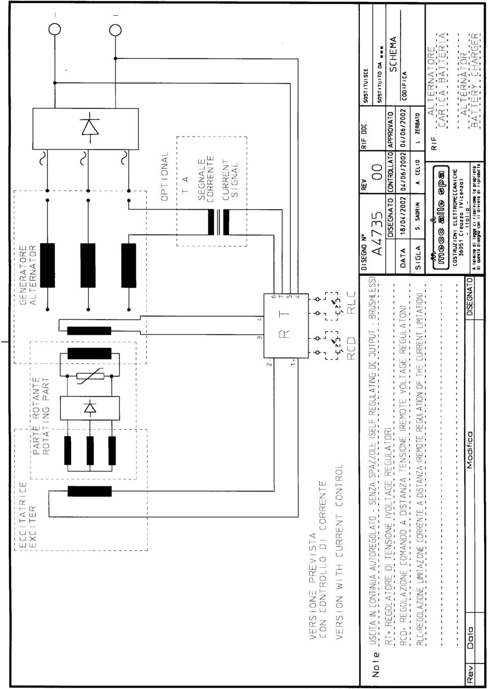
3 REGOLATORE DI TENSIONE PER CARICA BATTERIA RT XXX V YYY A Con la sigla RT si identificano tutti i regolatori per macchine in D.C. (alternatore + ponte di Graetz n-fase) usati generalmente come carica batteria. Lo schema di cablaggio generale è il N A4735/00; da questo schema si vede come l R.T. regoli la tensione dell alternatore variando la corrente di eccitazione in base ai valori misurati della tensione di batteria Vo (in D.C.) e di corrente di statore Is (in A.C.). Con XXX si indica la tensione di uscita, in D.C., della macchina completa, mentre con YYY la corrente nominale. La personalizzazione del regolatore avviene in fabbrica tramite il montaggio di uno specifico insieme di componenti che vanno a determinarne le caratteristiche di tensione, corrente e frequenza. Tramite trimmer, ed eventualmente potenziometri esterni, è possibile una taratura fine dei parametri menzionati. 1) COLLEGAMENTO CON IL GENERATORE Il collegamento con il generatore avviene sulla morsettiera CN1 come indicato nello schema N A2872/03; le funzioni dei morsetti sono indicate in Tab. 1. N Funzione Morsetto 1 Positivo statore eccitatrice 2 Negativo statore eccitatrice 3 Avvolgimento ausiliario di alimentazione 4 Massa (Avvolgimento ausiliario di alimentazione + Terminale positivo della batteria) 5 Terminale negativo della batteria 6 Secondario del trasformatore amperometrico 7 Secondario del trasformatore amperometrico Tab. 1: Connessioni della morsettiera di potenza CN1 2) COLLEGAMENTI PER CONTROLLI REMOTI E possibile remotare sia il controllo di tensione che la limitazione di corrente. REGOLAZIONE REMOTA DI TENSIONE La regolazione a distanza della tensione può essere effettuata tramite l inserzione di un potenziometro da 500K sui morsetti CN3 come indicato nel disegno allegato N A2872/03; il collegamento deve avvenire con una coppia (possibilmente schermata) di cavi unipolari intrecciati; l eventuale schermo deve essere connesso al morsetto 10 del connettore CN2 e alla carcassa del potenziometro. REGOLAZIONE REMOTA DELLA LIMITAZIONE DI CORRENTE La regolazione a distanza del valore di limitazione di RT (XXX V YYY A) VOLTAGE REGULATOR FOR BATTERY CHARGER By the mark RT we identify all the regulators for D.C. units (Alternator + n-phase Graetz bridge) usually used as battery chargers. The general wiring diagram is that you find on N A4735/00 drawing; by this wiring diagram it is possible to see how the RT regulates the alternator voltage varying the excitation current on the base of the measured values of the battery voltage (Vo, D.C. voltage) and stator current (Is, A.C. current). By XXX we point out the D.C. output voltage of the complete alternator and by YYY its rated current. The personalization of the regulator is done in the factory by the assembly of a specific set of components that defines the voltage, current and frequency characteristics. It is possible a fine calibration of the parameters mentioned above by trimmers or remote potentiometers. 1) CONNECTION TO THE ALTERNATOR The connection to the alternator is done by the terminal block CN1, as you can see on the N A2872/03 drawing; the functions of the terminals are pointed out in the following Table 1. Tab. 1: Connections to the power terminal block CN1 Terminal N 1 Positive exciter stator Function 2 Negative exciter stator 3 Feeding auxiliary winding 4 Earth (Feeding auxiliary winding + Positive terminal of the battery) 5 Negative terminal of the battery 6 Secondary windings of the amperometric transformer 7 Secondary windings of the amperometric transformer 2) CONNECTIONS FOR THE REMOTE CONTROLS It is possible to have both a remote control of the voltage and a remote current limitation. REMOTE VOLTAGE REGULATION The remote voltage regulation can be done by connecting a 500K potentiometer on CN3 terminals, as pointed out on the N A2872/03 drawing; the connection has to be done by a couple of unipolar and braided cables (screened, if possible); the screen, if used, has to be connected to the terminal n. 10 of the terminal block CN2 and to the casing of the potentiometer. REMOTE REGULATION OF THE CURRENT LIMI- TATION The remote regulation of the current limit can be done by connecting a 100K potentiometer on CN2 terminals, as pointed out on the N A2872/03 drawing; the connection

4 corrente può essere effettuata tramite l inserzione di un potenziometro da 100K sui morsetti CN2 come indicato nel disegno allegato N A2872/03; il collegamento deve avvenire con una terna (possibilmente schermata) di cavi unipolari intrecciati; l eventuale schermo deve essere connesso al morsetto 10 del connettore CN2 e alla carcassa del potenziometro. 3) CALIBRAZIONI I regolatori della serie RT sono dotati di 4 trimmer: uno per la taratura fine della tensione, uno per la soglia di intervento della protezione di bassa frequenza e due per la limitazione di corrente. Per la localizzazione dei trimmer di taratura si deve fare riferimento al disegno allegato A2872/03. TRIMMER P1: REGOLAZIONE DI TENSIONE Questo trimmer permette la variazione della tensione continua di uscita del generatore. Il valore di tale tensione dipende anche dallo stato in cui si trovano i morsetti CN3 (blocco arancione a 2 terminali). Se questi vengono cortocircuitati, la tensione è regolabile tra circa l 80% e il 110% della tensione nominale indicata nella sigla del regolatore (ad esempio: per RT28 la tensione può essere regolata tra circa 23 Vdc e 32 Vdc). Se i morsetti CN3 vengono lasciati liberi l intervallo di regolazione è più elevato. Ruotando il trimmer P1 in senso orario, la tensione di uscita aumenta, mentre, ruotandolo in senso antiorario, diminuisce. Per la calibrazione della tensione deve essere utilizzata la seguente procedura: 1. Ruotare il trimmer P1 tutto in senso antiorario; 2. Con il generatore a vuoto, portare il motore alla sua velocità nominale; 3. Ruotare il trimmer P1 in senso orario fino al valore desiderato della tensione di uscita; 4. L eventuale potenziometro remoto connesso sui morsetti CN3 permette di aumentare la tensione di uscita precedentemente impostata tramite il trimmer P1. TRIMMER P2: SOGLIA DI INTERVENTO DELLA PROTEZIONE DI BASSA FREQUENZA I regolatori della serie RT sono dotati di un circuito di limitazione della tensione di uscita in caso di diminuzione della frequenza generata. Fissata la soglia di intervento, la tensione diminuisce in modo proporzionale alla frequenza come rappresentato in Fig. 1. has to be done by a set of three unipolar and braided cables (screened, if possible); the screen, if used, has to be connected to the terminal n. 10 of the terminal block CN2 and to the casing of the potentiometer. 3) CALIBRATIONS The regulators of RT series have 4 trimmers: one is for the fine calibration of the voltage, one is for the adjustment of the intervention threshold of the low speed protection and two are for the current limitation. As for the location of the calibration trimmers, do reference to N A2872/03 drawing. P1 TRIMMER: VOLTAGE REGULATION This trimmer allows the adjustment of the D.C. output voltage of the alternator. The value of this voltage also depends on the condition in which the terminals of CN3 terminal block are (orange terminal block with two terminals). If these two terminals are bridged, the voltage is adjustable between about the 80% and the 110% of the rated voltage pointed out on the regulator mark (for instance: as for RT28 regulator, the voltage is adjustable between about 23 Vdc and 32 Vdc). If the two terminals of CN3 terminal block are free (no connection), the voltage regulation range is wider. Turning the P1 trimmer clockwise, the output voltage increases; turning the P1 trimmer anticlockwise, the output voltage decreases. For the voltage calibration the following procedure has to be followed: 1. Turn P1 trimmer anticlockwise completely; 2. Take the engine speed at its rated value with the alternator at no load; 3. Turn P1 trimmer clockwise in order to increase the output voltage to the desired value; 4. The remote potentiometer, if used, connected on the terminals of CN3 terminal block allows to increase the output voltage previously set by P1 trimmer. P2 TRIMMER: INTERVENTION THRESHOLD OF THE LOW SPEED PROTECTION The regulators of RT series have a circuit to limit the output voltage, when there is a decrease of the frequency (speed). Fixed the intervention threshold, the voltage decreases proportionally to the frequency, as pointed out in Chart 1. Vo nom Vo Velocità - Frequenza Speed - Frequency f th Fig. 1: Andamento qualitativo della tensione di uscita Vo in funzione della frequenza. Chart 1: Qualitative trend of the output voltage Vo in function of the frequency La frequenza di soglia fth viene regolata tramite il trimmer P2: se esso è ruotato tutto in senso orario la protezione è disattivata. Per la calibrazione della protezione di bassa frequenza deve essere utilizzata la seguente procedura : The threshold frequency fth is adjusted by P2 trimmer: if this trimmer is turned clockwise completely, then the protection is off. For the calibration of the low speed protection it has to be followed the following procedure :

5 1. Ruotare il trimmer P2 tutto in senso orario; 2. Con il generatore a vuoto, regolare la velocità del motore al valore al quale si desidera l intervento della protezione (ad esempio 1350 RPM per un alternatore a 1500 RPM, cioè circa il 10% in meno della velocità nominale); 3. Ruotare il trimmer P2 in senso antiorario fino a quando la tensione di uscita del generatore diminuisce del 7 10% (ad esempio potrebbe essere 26 Vdc per un RT28). TRIMMER P4 e P5: REGOLAZIONE DEL LIMITE DI CORRENTE Questi trimmer permettono di limitare il valore della corrente erogata dal generatore: quando entrambi sono ruotati in senso orario il limite è disinserito. Per la taratura della protezione amperometrica del regolatore si deve agire sui potenziometri P4 e P5 dello schema A2872/03 come segue: 1. Ruotare il trimmer P4 (MIN) completamente in senso orario; 2. Ruotare il trimmer P5 (MAX) completamente in senso antiorario; 3. A vuoto, si porti l alternatore alla velocità nominale e si verifichi tramite un tester che la tensione di uscita sia quella nominale indicata nel codice del regolatore; 4. Si connetta sull uscita un carico che comporti una corrente pari a circa il 20% della nominale (ad esempio 20 Adc se la corrente nominale è 100 Adc); 5. Ruotare il trimmer P4 in senso antiorario fino a quando la tensione continua in uscita è minore del 7 10% rispetto alla nominale (ad esempio potrebbe essere 26 Vdc per un RT28); 6. Lasciando il trimmer P4 al valore precedentemente impostato, ruotare il trimmer P5 completamente in senso orario; 7. Si connetta in uscita un carico che comporti una corrente superiore del 20% rispetto alla nominale (ad esempio 120 Adc se la corrente nominale è 100 Adc). 8. Ruotare il trimmer P5 in senso antiorario fino ad una posizione per la quale la corrente erogata dal generatore è pari alla corrente nominale (ad esempio 100 Adc nel caso precedente). 9. Misurando la tensione continua in uscita dall alternatore questa dovrebbe essere minore del 7 10% rispetto alla nominale. N.B. : Qualora non fosse possibile la taratura della minima corrente con la procedura indicata ai punti 4 e 5 (ad esempio perchè il carico è costituito da una batteria piuttosto scarica), si deve: 5A. Ruotare il trimmer P4 (MIN) completamente in senso antiorario; 5B. Posizionare il trimmer P4 sulla 3a o 4a tacca ruotandolo in senso orario; 5C. Proseguire la procedura di taratura dal punto 6. 4) ALLEGATI : Schema generale di cablaggio: Disegno N A4735/00 Disposizione dei morsetti e delle tarature nei regolatori serie RT: Disegno N A2872/ Turn P2 trimmer clockwise completely; 2. Take the alternator at its nominal speed (at no load) and then set the engine speed at the value you want the intervention of the protection (for instance, 1350 RPM for an alternator working at 1500 RPM, that is, about 10% less than its nominal speed); 3. Turn P2 trimmer anticlockwise until the output voltage of the alternator decreases about 7 10% of the rated voltage (for instance, it could be 26 Vdc for a RT28 regulator). P4 AND P5 TRIMMERS: CURRENT LIMIT REGULATION These trimmers allow to limit the current value supplied by the alternator: when both the trimmers are turned clockwise completely, the current limitation is off. The calibration of the amperometric protection of the regulator is done by P4 and P5 potentiometers (see N A2872/03 drawing) following this procedure: 1. Turn P4 trimmer (MIN) clockwise completely; 2. Turn P5 trimmer (MAX) anticlockwise completely; 3. Take the alternator at its nominal speed and, at no load, check by a tester that the output voltage is at its nominal value, as pointed out on the regulator code. 4. Load the alternator in such a way to have a current equal to the 20% of the rated current (for instance, 20 Adc, if the rated current is 100 Adc); 5. Turn P4 trimmer anticlockwise until the D.C. output voltage is 7 10% lower than the rated voltage (for instance, it could be 26 Vdc for a RT28 regulator). 6. Leave P4 trimmer at the value set previously and then turn P5 trimmer clockwise completely. 7. Load the alternator in such a way to have a current more than 120% the rated current (for instance, 120 Adc, if the rated current is 100 Adc). 8. Turn P5 trimmer anticlockwise until the current supplied by the alternator is equal to the rated current (for instance, 100 Adc, if the rated current is 100 Adc). 9. The measurement of the D.C. output voltage of the alternator should be 7 10% lower than the rated voltage. NOTE : In case it is not possible to calibrate the minimum current by the procedure pointed out on the items n. 4 and 5 above (for instance, the load is a flat battery ), you have to do as follows: 5A. Turn P4 trimmer (MIN) anticlockwise completely ; 5B. Locate P4 trimmer on the 3rd or 4th notch turning clockwise; 5C. Continue the calibration procedure from item n. 6. 4) ENCLOSURES : General wiring diagram: N A4735/00 drawing Arrangement of the terminals and calibrations on the regulators of RT series: N A2872/03 drawing.

6
7

SAIR NICOTRA-GEBHARDT-FAN.RU ELETTROVENTILATORI CENTRIFUGHI A SEMPLICE ASPIRAZIONE DIRETTAMENTE ACCOPPIATI DIRECT DRIVEN SINGLE INLET CENTRIFUGAL FANS
 SAIR ELETTROVENTILATORI CENTRIFUGHI A SEMPLICE ASPIRAZIONE DIRETTAMENTE ACCOPPIATI DIRECT DRIVEN SINGLE INLET CENTRIFUGAL FANS CATALOGO PROVVISORIO - APRILE 2003 DRAFT CATALOGUE - APRIL 2003 GAMMA E CODICI
SAIR ELETTROVENTILATORI CENTRIFUGHI A SEMPLICE ASPIRAZIONE DIRETTAMENTE ACCOPPIATI DIRECT DRIVEN SINGLE INLET CENTRIFUGAL FANS
 SAIR ELETTROVENTILATORI CENTRIFUGHI A SEMPLICE ASPIRAZIONE DIRETTAMENTE ACCOPPIATI DIRECT DRIVEN SINGLE INLET CENTRIFUGAL FANS CATALOGO PROVVISORIO - APRILE 2003 DRAFT CATALOGUE - APRIL 2003 GAMMA E CODICI
REGOLATORE DI TENSIONE / VOLTAGE REGULATOR M40FA610A
 REGOLATORE DI TENSIONE / VOLTAGE REGULATOR APPLICAZIONE Il regolatore di tensione tipo W1 è adatto per generatori sincroni di costruzione MARELLI MOTORI, della serie M8B, per le grandezze 160-500. Questo
TLR05S-350. Extender in corrente costante, 3 x 350mA per TLR04M_
 TLR05S-350 Extender in corrente costante, 3 x 350mA per TLR04M_350-500 IT DATI TECNICI Alimentazione Uscita Tipo di carico Sistema di collegamento master/slave/slave Distanza massima delle connessioni
Appendice A. Conduttori elettrici, sezioni e diametri Appendix A. Wires, Sizes and AWG diameters
 Appendice A. Conduttori elettrici, sezioni e diametri Appendix A. Wires, Sizes and AWG diameters A.1 Misura dei conduttori elettrici, sezioni e diametri AWG and kcmil wires sizes measurement L America
SISTEMA DI ILLUMINAZIONE PER VERRICELLI WINDLASS LIGHTING SYSTEM
 Istruzioni per l uso Instructions for use SISTEMA DI ILLUMINAZIONE PER VERRICELLI WINDLASS LIGHTING SYSTEM WLS WINDLASS LIGHTING SYSTEM - 1 - Rev.01-2013 Italiano SISTEMA DI ILLUMINAZIONE PER VERRICELLI
Expansion card. EXP-D8-120 I/O Interface Card 8 AC Opto-coupled Digital Inputs 8 DC Digital Outputs
 Expansion card EXP-D8-120 I/O Interface Card 8 AC Opto-coupled Inputs 8 DC Outputs Sommario / Contents Vi ringraziamo per avere scelto questo prodotto Gefran-Siei. Saremo lieti di ricevere all'indirizzo
PROTEZIONI TERMICHE E SCALDIGLIE ANTICONDENSA
 PROTEZIONI TERMICHE E SCALDIGLIE ANTICONDENSA INDICE 1) PROTEZIONI TERMICHE 1.1) TERMISTORI PTC 1.2) TERMORESISTENZE PT100 1.3) PROTETTORI TERMICI BIMETALLICI 2) SCALDIGLIE ANTICONDENSA 1/4 Accessori_01.doc
Centrale MK3 MK3 power packs
 Centrale power packs Manuale di regolazione Adjusting manual - Installare la centrale sulla rampa e collegare i raccordi idraulici A e B come nell immagine sottostante. - Instal the power pack on the dock
SOMMATORE / SOTTRATTORE - SEPARAZIONE GALVANICA
 SOMMATORE / SOTTRATTORE - SEPARAZIONE GALVANICA S190 Strumento conforme alle prescrizioni sulla compatibilità elettromagnetica (direttiva 89/366/CEE.) Norme di riferimento: EN 50081-2 Norma Emissione -
verled DDS.682 Overled is a brand of DDS Elettronica S.r.l. - Via Nicolò Biondo Modena Italy -
 O is a brand of Elettronica.r.l. - Via Nicolò Biondo 171-41100 Modena Italy - www.o.com AC immable Constant Current/Voltage LE power supply 682 è un alimentatore per Led con uscita o in corrente costante
controlli di livello capacitivi capacitive levels controls
 controlli di livello capacitivi capacitive levels controls SENSORI CAPACITIVI ALTA TEMPERATURA SC18M-HT/SC30M-HT HIGH TEMPERATURE CAPACITIVE SENSORS SC18M-HT/SC30M-HT MODELS GENERALITÀ GENERAL DETAILS
Schema dei collegamenti Main connection diagram S2 Caratteristiche tecniche Technical features S2 Dimensioni Dimensions S3 Opzioni Options S3
 Schema dei collegamenti Main connection diagram S2 Caratteristiche tecniche Technical features S2 Dimensioni Dimensions S3 Opzioni Options S3 PLN20 PLN40 Schema dei collegamenti Main connection diagram
Istruzioni per l uso. Instructions for use REGOLATORE DI VELOCITA SPEED REGULATOR RPWM001
 Istruzioni per l uso Instructions for use REGOLATORE DI VELOCITA SPEED REGULATOR RPWM001 Rev. 01 2013 Italiano REGOLATORE DI VELOCITA RPWM001 Il regolatore di velocità RPWM001 è ideale per variare la velocità
INTECNO TRANSTECNO. MICRO Encoder ME22 ME22 MICRO Encoder. member of. group
 INTECNO MICRO ME22 ME22 MICRO 2 0 1 5 member of TRANSTECNO group Pag. Page Indice Index Descrizione Description I2 Caratteristiche principali Technical features I2 Designazione Classification I2 Specifiche
SRT064 BTH SRT051 BTH SRT052 BTH
 KIT FOR TRUCK BRAKE TESTERS SRT051 BTH SRT052 BTH OPERATOR S MANUAL SRT064BTH SRT051BTH SRT052BTH CONTENTS 1. INTRODUCTION...1 2. Description of SRT064BTH Kit...2 3. Description of SRT051BTH Kit...2 4.
PLC2 ELECTRONIC BOARD SCHEDA ELETTRONICA PLC2
 APPLICATION NOTES NOTE DI APPLICAZIONE January 005 Gennaio 005 PLC ELECTRONIC BOARD SCHEDA ELETTRONICA PLC g TeKne Dental s.r.l. Via del Pescinale 77-50041 Calenzano (FI) - ITALY [email protected] www.teknedental.com
DATI TECNICI - TECHNICAL DATA
 APPLICAZIONE Il regolatore di tensione tipo MARK I è adatto per generatori sincroni di costruzione MARELLI MOTORI, della serie MJB, per le grandezze 160-500. Questo regolatore è appropriato per funzionare
sensori per cilindri magnetic sensors for cylinders
 Schema di collegamento: fili Wiring diagram: wires Modello Model RS1-A RS-A RS5-C RS-A RS-A Funzione Function Reed NC Reed NC Numero fili Number of wires Lunghezza cavo Lenght of wires Connettore Connector
Generatori ad inverter ed elettronici per saldatura MMA e TIG lift
 Generatori ad inverter ed elettronici per saldatura e lift Inverter and electronic power sources for and lift welding Inverter: SKYLINE 1500 S 200 S 300 S 460 Elettronici - Electronic: SC 350 SC 500 SC
Alimentatori per LED di segnalazione (MINILED) Power supply units for Signal LEDs (MINILED)
 Power supply units for Signal LEDs (MINILED)") Alimentatori per LED di segnalazione (MINILED) Power supply units for Signal LEDs (MINILED) Alimentatori elettronici con tensione di uscita stabilizzata per moduli LED di segnalazione. Led driver with
Alimentatori per LED di segnalazione (MINILED) Power supply units for Signal LEDs (MINILED) Alimentatori elettronici con tensione di uscita stabilizzata per moduli LED di segnalazione. Led driver with
TRANSTECNO MOTORI ELETTRICI ELECTRIC MOTORS. MS 6324 B Hz. MY 6324 B Hz. Caratteristiche tecniche. Technical characteristics
 Indice Index Caratteristiche tecniche Technical characteristics N2 esignazione esignation N2 ati tecnici Technical data N3 imensioni motori trifase serie MS - B5 MS - B5 Series three phase motors dimensions
Light intensity regulator for Aim LED. Regolatore d intensità luminosa per Aim LED
 X Light intensity regulator for Aim LED Continuous regulation Light intensity memory Soft start Soft stop Light intensity regulation Min. 30% Max. 100% Runs from 1 to 5 Aim Dimmer that needs to be inserted
ELCART. Manuale di istruzioni/scheda tecnica. Alimentatore Switching 60W UPS 13/26500 (Mod. VIC-60-12UPS)
") PAGINA 1 DI 6 Alimentatore Switching 60W UPS 13/26500 (Mod. VIC-60-12UPS) NOTA! LEGGETE ATTENTAMENTE QUESTO MANUALE DI ISTRUZIONI PRIMA DI INSTALLARE QUESTO ALIMENTATORE. Prima della prova e messa in servizio
PAGINA 1 DI 6 Alimentatore Switching 60W UPS 13/26500 (Mod. VIC-60-12UPS) NOTA! LEGGETE ATTENTAMENTE QUESTO MANUALE DI ISTRUZIONI PRIMA DI INSTALLARE QUESTO ALIMENTATORE. Prima della prova e messa in servizio
MST_K12_FAN. Regolatore di velocita per ventole PC. Manuale d uso e d installazione
 MST_K12_FAN Regolatore di velocita per ventole PC Manuale d uso e d installazione Page 1 of 7 Indice Argomenti 1.0 Revisioni. pag. 3 2.0 Introduzione.... pag. 3 2.1 Caratteristiche generali... pag. 3 3.0
S.R.7/2 1.1) OPERATION PRINCIPLE 1.1) PRINCIPIO DI FUNZIONAMENTO
 OPERATION PRINCIPLE 1.1) PRINCIPIO DI FUNZIONAMENTO") S.R.7/2 1) REGOLATORE ELETTRONICO S.R.7/2 1) S.R.7/2 ELECTRONIC REGULATOR 1.1) PRINCIPIO DI FUNZIONAMENTO 1.1) OPERATION PRINCIPLE Il diagramma fondamentale é illustrato in fig. 1; se lo si osserva con
S.R.7/2 1) REGOLATORE ELETTRONICO S.R.7/2 1) S.R.7/2 ELECTRONIC REGULATOR 1.1) PRINCIPIO DI FUNZIONAMENTO 1.1) OPERATION PRINCIPLE Il diagramma fondamentale é illustrato in fig. 1; se lo si osserva con
ISTRUZIONI. Codice: LEMC30 v2.0 VOLTAGE Usa il QRcode per scaricare il foglio di istruzioni sul tuo smartphone/tablet.
 ISTRUZII Codice: v2.0 Alimentatore LED multicorrente dimmerabile Alimentatore LED multicorrente dimmerabile. Alimentatore ad uso indipendente. Corrente di uscita costante: 250-700mA (impostabile tramite
USER MANUAL 2AMIN521VS
 USER MANUAL 2AMIN521VS SUBJECT INDEX: DESCRIPTION TECHNICAL SPECIFICATION FUNCTIONAL DESCRIPTION DEVICE POWER SUPPLY AND CONNECTION TO THE LED MODULE SINGLE POWER SUPPLY MODE MULTIPLE POWER SUPPLY MODE
ISTRUZIONE DI SERVIZIO SERVICE INSTRUCTION
 ISTRUZIONE DI SERVIZIO SERVICE INSTRUCTION Procedura sostituzione motore tipo VALEO 404 864 rotazione braccio ROTOGRAPH PLUS Replacing the arm rotation motor type VALEO 404 864 on the ROTOGRAPH PLUS NOTA:
Exam of ELECTRONIC SYSTEMS June 17 th, 2014 Prof. Marco Sampietro
 Exam of ELETRONI SYSTEMS June 17 th, 2014 Prof. Marco Sampietro Matr. N NAME Problem 1 Operational Amplifier circuit 1. onsiderare il circuito seguente, in cui l Amplificatore Operazionale sia ideale,
U.V.R.6 2) U.V.R.6 ELECTRONIC REGULATOR
 U.V.R.6 ELECTRONIC REGULATOR") 2) REGOLATORE ELETTRONICO U.V.R.6 U.V.R.6 2) U.V.R.6 ELECTRONIC REGULATOR 2.1) Caratteristiche generali Il regolatore di tensione tipo UVR6 é un regolatore elettronico di progettazione avanzata, che assicura
2) REGOLATORE ELETTRONICO U.V.R.6 U.V.R.6 2) U.V.R.6 ELECTRONIC REGULATOR 2.1) Caratteristiche generali Il regolatore di tensione tipo UVR6 é un regolatore elettronico di progettazione avanzata, che assicura
U.V.R.6 - U.V.R.6-H400
 U.V.R.6 - U.V.R.6-H400 2) REGOLATORE ELETTRONICO U.V.R.6 E U.V.R.6-H400 2.1) Caratteristiche generali I regolatori di tensione della famiglia UVR6 sono regolatori elettronici di progettazione avanzata,
Appendice E - Appendix E PANNELLI FOTOVOLTAICI - PHOTOVOLTAIC PANELS
 Appendice E - Appendix E PANNELLI FOTOVOLTAICI - PHOTOVOLTAIC PANELS I sistemi mod. i-léd SOLAR permettono di alimentare un carico sia in bassa tensione 12-24V DC, sia a 230v AC, tramite alimentazione
Regolatore di velocità per motori DC SPEEDREGULATOR 1/8
 Regolatore di velocità per motori DC DC DCSPEED SPEEDREGULATOR REGULATOR 1/8 Descrizione La DC_SPEED_REG permette la regolazione della velocità di un motore in corrente continua a spazzole oppure ad induzione
REGOLATORE DI COSϕ / POWER FACTOR REGULATOR M50FA400A
 REGOLATORE DI COSϕ / POWER FACTOR REGULATOR APPLICAZIONE Il regolatore del fattore di potenza viene utilizzato per il controllo dell eccitazione in generatori funzionanti in parallelo con la rete. Tale
Appendice D - Appendix D DRIVER - DRIVERS
 Appendice D - Appendix D DRIVER - DRIVERS Driver per led a 1 watt - Drivers for leds at 1 watt 84325 1 1 190...265V AC 12V DC - 350mA 84326 2 3 190...265V AC 12V DC - 350mA 84327 1 6 190...265V AC 24V
NDCMG NDCMG MOTORIDUTTORI C.C. AD INGRANAGGI CILINDRICI RARE EARTH D.C. HELICAL GEARMOTORS
 Pag. Page Indice Index Caratteristiche tecniche Technical features C2 Designazione Classification C2 Sensi di rotazione Direction of rotation C3 Lubrificazione Lubrication C3 Simbologia Symbols C3 Carichi
Catalogo Catalogue E1W 06-05
 Catalogo Catalogue E1W 06-05...THE ELECTRIC GENERATION - - - - E1W AC ALTERNATORI/SALDATRICI AC SENZA SPAZZOLE (A CONDENSATORE) BRUSHLESS ALTERNATORS/AC WELDERS (WITH CAPACITOR) La serie E1W AC è costituita
DDS.682. C.F. partita Iva It02275360366 - capitale i. V. 50.000,00euro - telefono +39.059.822993 fax +39.059.823573
 O is a brand of Elettronica.r.l. - Via Nicolò Biondo 171-41100 Modena Italy - www.o.com AC immable Constant Current/Voltage LE power supply 682 è un alimentatore per Led con uscita o in corrente costante
MD2208. Multi I/O Control Module D32305 Rev. B. Microdata Due Martec Group
 MD2208 Multi I/O Control Module D32305 Rev. B Descrizione Si tratta di unità, collegabili sul Loop dei sistemi di rilevamento incendio (FDS) della serie MD9800 o sul Branch dei sistemi della serie MD2010,
Gateway Bacnet Multichiller series
 Servizio egolazione e Controllo File Pagina 1/11 Gateway Bacnet Multichiller series Servizio egolazione e Controllo File Pagina 2/11 CONTENTS 1. PCOWEB INSTALLATION... 3 2. BACNET MAPPING... 5 3. PCO COMMUNICATION
Design, Quality & Production Made in Italy GENERATORI D ARIA. Scheda Tecnica Data Sheet. Caldaie Termostufe Termocamini Stufe
 Design, Quality & Production Made in Italy Scheda Tecnica Data Sheet Caldaie Termostufe Termocamini Stufe www.pasqualicchio.it Caratteristiche tecniche / Technical Specifications 40 60 80 120 150 200 270
M63FA310A. Manuale dell Utente - User Manual SIN.NT Regolatore di Tensione per Generatori Sincroni Trifase
 M63FA310A Email: Manuale dell Utente - User Manual Regolatore di Tensione per Generatori Sincroni Trifase Automatic Voltage Regulator for Three-phase Synchronous Generators (Issued: 05.2010) SIN.NT.014.5
MANUALE OPERATIVO / INSTRUCTION MANUAL IM200-IU v1.3 CT / CTD CT / CTD. Toroidal current transformers. Trasformatori di corrente toroidali. pag.
 MANUALE OPERATIVO / INSTRUCTION MANUAL IM200-IU v1.3 CT / CTD Trasformatori di corrente toroidali CT / CTD Toroidal current transformers pag. 1 / 5 ATTENZIONE!!! Leggere attentamente il manuale prima dell
INVERTER MMA POWER ROD 131
 INVERTER MMA POWER ROD 131 POWER ROD 131 Art. 256 230V 50/60 Hz + 15% / -20% 16 A 4,0 KVA 30% 3,3 KVA 60% 3,0 KVA 100% Dati tecnici Specifications Alimentazione monofase Single phase input Fusibile ritardato
Info Tecniche Technical Info. Esempi di montaggio Assembling examples
 08 Info Tecniche Esempi di montaggio Assembling examples 08 Nota: Qui di seguito vengono riportati alcuni schemi tipici di collegamento in corrente costante e in tensione costante per LED e Strip. Eseguire
M40FA640A/A - Mark I. Manuale dell Utente - User Manual. Regolatore di Tensione per Generatori Sincroni Trifase
 M40FA640A/A - Mark I Manuale dell Utente - User Manual Regolatore di Tensione per Generatori Sincroni Trifase Automatic Voltage Regulator for Three-phase Synchronous Generators INTRODUZIONE La presente
MOSAIC MOR4/MOR4S8 RELAY OUTPUT EXPANSION UNIT
 MOSAIC MOR4/MOR4S8 RELAY OUTPUT EXPANSI UNIT MOR4 e MOR4S8 sono moduli di sicurezza appartenenti alla famiglia Mosaic dotati di 4 uscite a relè di sicurezza indipendenti con relativi 4 ingressi per i contatti
RCM-1 ELECTRONIC REGULATOR FOR CAPACITOR GENERATORS OPERATING INSTRUCTIONS
 REGOLATORE ELETTRONICO RCM-1 PER GENERATORI A CONDENSATORE ISTRUZIONI PER L USO RCM-1 ELECTRONIC REGULATOR FOR CAPACITOR GENERATORS OPERATING INSTRUCTIONS 1 November 2004 rev. 05 Per un corretto funzionamento
Alimentatori. Power supply
 / 143 DAYLIGHTALIA Power supply DAYLIGHTALIA 144 / Alimentatore tensione costante onstant Voltage Driver e regolatori di luce - Power supply and light controller A B aratteristiche costruttive Alimentatore
Finite Model Theory / Descriptive Complexity: bin
 , CMPSCI 601: Recall From Last Time Lecture 19 Finite Model Theory / Descriptive Compleity: Th: FO L DSPACE Fagin s Th: NP SO. bin is quantifier-free.!#"$&% ('*), 1 Space 0 1 ) % Time $ "$ $ $ "$ $.....
RELAY interface for HF, HF Line, HF Top Line, Ally and Megaline series
 V9434D RELAY interface for HF, HF Line, HF Top Line, Ally and Megaline series ITALIANO...pag. ENGLISH...pag. 5 1 ISTRUZIONI PER L USO Un gruppo di continuità (UPS) è un alimentatore funzionante a batteria
GENERATORE DI RAMPA MODELLO: RMP-97
 GENERATORE DI RAMPA MODELLO: RMP-97 1 PRECAUZIONI E SICUREZZA NON LAVORARE MAI SUL MOTORE, AZIONAMENTO O CIRCUITI AUSILIARI SENZA AVER DISINSERITO L ALIMENTAZIONE GENERALE DELL APPARECCHIATURA IL PRODOTTO
Unità Rotostatoriche Alta Frequenza High Frequency Rotor/Stator Units VERSIONI, CARATTERISTICHE MECCANICHE E PRESTAZIONI VERSIONS, MECHANICAL
 Unità Rotostatoriche Alta High Frequency Rotor/Stator Units VERSIONI, CARATTERISTICHE MECCANICHE E PRESTAZIONI VERSIONS, MECHANICAL CHARACTERISTICS AND PERFORMANCES Caratteristiche dimensionali e Prestazioni
M16FA655A - Mark V. Manuale dell Utente - User Manual SIN.NT.002.5. Regolatore di Tensione per Generatori Sincroni Trifase
 M16FA655A - Mark V Manuale dell Utente - User Manual Regolatore di Tensione per Generatori Sincroni Trifase Automatic Voltage Regulator for Three-phase Synchronous Generators SIN.NT.002.5 Instruction Manual
Idoneità ai climi Caldo umido, costante, secondo IEC Caldo umido, ciclico secondo IEC
 Pressostato,1W,15bar Tipo MCS11 Codicenumerico 088527 CatalogNo. MCS11 Programmadifornitura Assortimento Pressostato con contatti ausiliari Grado di protezione IP65 Contatti 1 contatto di scambio Pressionedidisinserzione/inserzione:
REGOLATORE DI TENSIONE TIPO W2 / VOLTAGE REGULATOR TYPE W2 M63FA310A
 REGOLTORE DI TENSIONE TIO W / VOLTGE REGULTOR TYE W M6F0 LICZIONE Il regolatore di tensione tipo W è adatto per generatori sincroni di costruzione MRELLI MOTORI, della serie M7 - M8. Il regolatore è completamente
QK-RADAROMNI. User Manual Manuale d uso V03. w w w. q u i k o i t a l y. c o m
 QK-RADAROMNI User Manual Manuale d uso V03 w w w. q u i k o i t a l y. c o m ATTENZIONE!! Prima di effettuare l'installazione, leggere attentamente questo manuale che è parte integrante di questa confezione.
SENSORI CAPACITIVI CAPACITIVE SENSORS
 SENSORI CAPACITIVI CAPACITIVE SENSORS Copertine Aeco_cat_Generale.indd 2 SENSORI CAPACITIVI ALTA TEMPERATURA HIGH TEMPERATURE CAPACITIVE SENSORS 07/04/14 16.40 SENSORI CAPACITIVI ALTA TEMPERATURA SC18M-HT/SC30M-HT
M40FA640A/A - Mark I. Manuale dell Utente - User Manual SIN.NT Regolatore di Tensione per Generatori Sincroni Trifase
 M40FA640A/A - Mark I Email: Manuale dell Utente - User Manual Regolatore di Tensione per Generatori Sincroni Trifase Automatic Voltage Regulator for Three-phase Synchronous Generators (Issued: 09.2011)
User Manual. Rev Date: 31/05/2018
 Size / Misure 8 50 500 60 150 POWER IN DMX IN DMX OUT 9 4. POWER+DMX out cable + M8 Female Connector 16,80 Connection kit included with the Startline cable / Kit di connessione compreso alla startline
Batterie Avviamento ed Accessori Listino vendita IVA esclusa
 Modelli consigliati: Suggested models: 13 04 A 13 06 A 1304 A 1306 A 1308 A 1310 R Pag. 1 di 5 Tecno 2 srl 1308 A 1310 R 1313R 1318 R 1326 R 1313 R Stra del Cascinotto 139/43 Torino (TO) Italy Tel. 0039
GAB. Scheda Tecnica Data Sheet. Caldaie Termostufe Termocamini Stufe Design, Quality & Production Made in Italy
 Design, Quality & Production Made in Italy Scheda Tecnica Data Sheet Caldaie Termostufe Termocamini Stufe www.pasqualicchio.it Caratteristiche tecniche / Technical Specifications 40 60 80 120 150 200 270