Table of contents, English Indice, Italiano
|
|
|
- Emanuele Baldi
- 8 anni fa
- Visualizzazioni
Transcript
1
2 Table of contents, English Drawings HWAM Autopilot IHS TM...6 Installation Remote control...11 Firing manual - wood...14 Firing in general...16 Maintenance...18 Operational problems...19 Declaration of Performance...19 Type plate Indice, Italiano Disegni HWAM Autopilot IHS TM...20 Istruzioni per l installazione...21 Telecomando...25 Uso iniziale della stufa...28 Ragguagli generali...31 Manutenzione...32 Disturbi del funzionamento...33 Dichiarazione di prestazione...33 Targa dati

3
4 E. 4
5 F

6
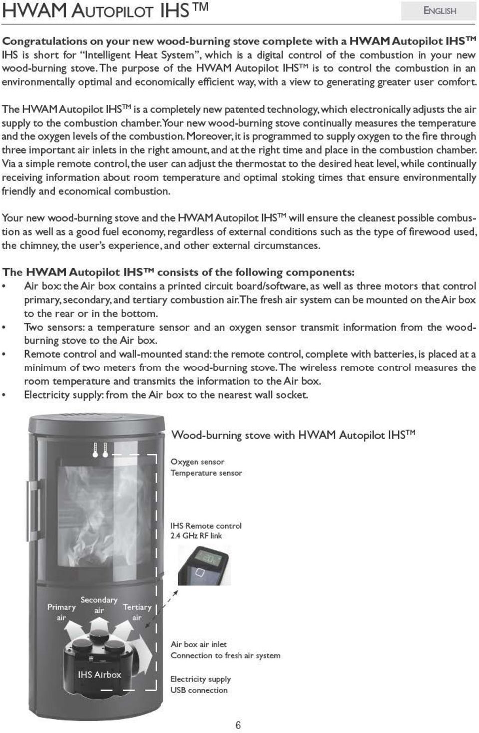
7 Installation General information Installation of your HWAM woodburning stove must always comply with local building regulations. It is a good idea to consult your local chimney sweep before installing, since he will be the one to sweep the chimney and stove. Always follow the instructions of the manual carefully and make sure that the installation is carried out by a qualified professional. HWAM packaging material should always be handled in accordance with the local rules for waste handling. Room requirements There must be a constant supply of fresh air to the room in which the stove is to be installed. The woodburning stove uses approx m 3 air per hour. In comparison, a modern cooker hood sucks up to 1000m 3 air per hour. A window that opens or an adjustable air vent should be sufficient, but it is also possible to connect the stove to a HWAM fresh air system. The air inlet/grating must be placed so that they do not become blocked. Please be aware that not all glass parts are heat-resistant. For this reason, a glass wall should sometimes be treated as a flammable wall, in which case we ask you to contact your local chimney sweep or glass producer to hear at what distance the stove should be kept from glass. Load-bearing capacity of floor Before installing the stove, you must ensure that the load-bearing capacity of the floor can withstand the weight of the stove and the chimney. The weight of the chimney should be calculated according to its dimensions and height. Technical data Model Weight Height Width Dept HWAM 2610c/2620c with plinth 66 kg 73.0 cm 43.0 cm 36.9 cm HWAM 2610c/2620c with wall bracket 64 kg 70.0 cm 43.0 cm 40.4 cm HWAM 2610m/2620m with plinth 64 kg 73.0 cm 43.0 cm 36.9 cm HWAM 2610m/2620m with wall bracket 62 kg 70.0 cm 43.0 cm 40.4 cm HWAM 2630c/2640c 75 kg cm 43.0 cm 36.9 cm HWAM 2630m/2640m 73 kg cm 43.0 cm 36.9 cm The stove is mainly made of sheet iron, with some items made of cast iron. The HWAM Autopilot IHS TM is an electronic product primarily consisting of plastic, a printed circuit board and wires. Test results from nominal test EN Nominal heating effect 4.5 kw Smoke temperature 280ºC Exhaust gas flow 3.55 g/s Efficiency 81.3 % The test result according to NS 3058 Particle emission 2.20 g/kg Distance to inflammable materials Your HWAM woodburning stove should always be installed on a non-combustible hearth. If it is installed on a wooden floor or similar, the floor must be covered with a non-combustible material. If HWAM 2610/2620 is placed on a flammable floor, always mount it on a plinth whether or not the 7

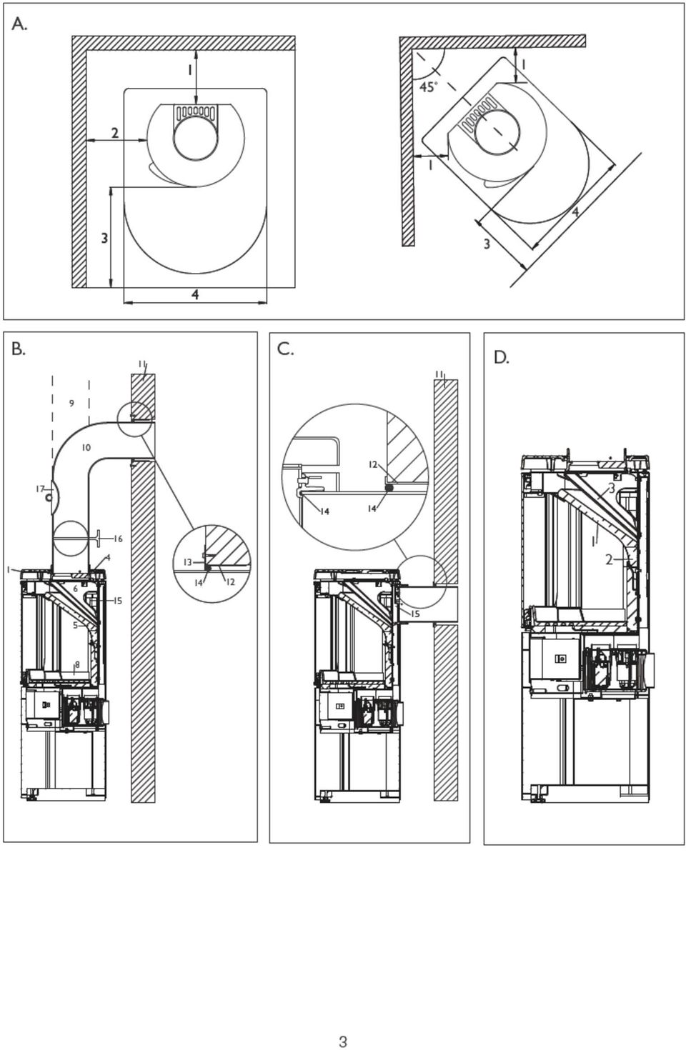
8 floor is covered by a non-flammable material, such as a plate of glass or steel. The plinth is an accessory. Contact your HWAM dealer for more information. Drawing A HWAM 2610 HWAM 2630 HWAM 2610 HWAM Recommended for brick wall 10 cm 10 cm 1. For inflammable back wall 19 cm 19 cm 2. For inflammable side wall 36 cm 36 cm 1.To inflammable wall,corner installation 34 cm* 20 cm* 3. Distance to furnishings in front 80 cm 80 cm *All dimensions in connection with corner installation are only recommendations. Contact your chimney sweep for a clarification. For wall-mounting, HWAM 2610/2620 must be placed at least 3 cm above any inflammable flooring. This also applies to any floorboard placed on the floor. Remember to pay attention to any regulations concerning the required distance between the wall and smoke pipe. The distance to a brick wall is set to faciliate the servicing of the HWAM Autopilot IHS TM. HWAM 2610/2620 may be mounted with wall fittings only on a brick wall. The stove must be taken down when the HWAM Autopilot IHS TM is to be serviced. Requirements for chimney and smoke pipe The chimney must be of a sufficient height to enable an adequate draft and to prevent smoke problems. The stove requires a draft of at least 12 Pa. The chimney must have a minimum opening equivalent to Ø 150 mm. The chimney opening should always be at least the size of the outlet socket of the stove. The chimney must have an easily accessible soot door. Smoke pipe and chimney must always be suitable for a stove connection. Ask your HWAM dealer for more information. Changing the smoke outlet from top outlet to rear outlet (drawing F) 1. Lift the cast-iron top (1) off the stove. 2. Remove the rear plate of the stove by loosening the two screws (2). 3. Remove the cover plate (3). 4. Remove the flue ring (4) and fasten it to the rear of the stove. 5. Carefully fold the wires and fasten by pressing the metallic tabs (5). 6. Break off the cut-out (6) in the rear plate and fasten the rear plate to the stove again. Be careful not to jam the wires when installing the rear plate. 7. Fasten the cover plate (3) to the top of the stove. 8. Place the cast-iron top (1) on the stove. 9. Place the cast-iron top cover (7) in the hole in the cast-iron top plate. Connection to chimney All the stoves have both rear and top smoke outlet that can be connected to an approved steel chimney on top or directly out at the rear to a chimney. Make sure that the chimney is tight and that no false draft is caused around neither the cover plate, in connection with a covered smoke outlet, nor the cleanout door and pipe connections. Please note that bent and/or horizontal smoke pipes will reduce the effect of the chimney draft. Vertical cross-section of smoke flue (Drawing B and C) B: Top smoke outlet C: Rear smoke outlet 8

9 Steel chimney (9). Flue gas elbow (10). Fits into smoke flue socket. Brick-built jamb of flue (11). Built-in pipe sleeve (12). Fits smoke flue. Wall rosette (13). Covers disruption to wall around pipe sleeve. Joint (14). Sealed with packing material. Smoke outlets (15) of the HWAM stove. Smoke flue regulating damper (16). Soot door (17). Fitting the loose parts Before the stove is installed, you must ensure that all loose parts are fitted correctly. Vertical cross-section of the stoves (Drawing B): The smoke shelf (5): Should rest on the rear plate and on the stand uppermost in the front of the combustion chamber. The baffle plate (6): Is suspended on two hooks, one in either side uppermost in the combustion chamber. To mount the baffle plate, lift it to a position at the very top of the combustion chamber, and then push it back until it falls into place in the two hooks. When the stove is installed, the transport protection is removed. Lift the smoke shelf up and forward. Then lower it and remove it from the combustion chamber. Subsequently, the transport protection is bent downwards/forwards until it is vertical. The cast iron bottom plate (8): Must be in a flat position at the bottom of the combustion chamber. Connecting and preparing the HWAM Autopilot IHS TM 1. Connect the plug a) to a normal 230V socket b) to the Air box in the wood section underneath the combustion chamber (lead the plug through the air slot at the bottom between the side and rear plates - on the left side of the wood-burning stove when seen from the front. There is a mark on the Air box where the plug should be let in. See the photo of the power supply on the Air box. Air box without power supply Air box with power supply 2. Insert three AA batteries in the remote control. When the IHS logo disappears from the display, the remote control is ready to use. 3. The remote control and the wood-burning stove must be connected (the factory will see to this). If the status line at the bottom of the display is clear (empty) ( )and divided into three sections, the wood-burning stove and the remote control are connected. If the status line is dotted ( ), the remote control and the wood-burning stove are not connected. Start with a display in which the light is off, and make the connection by pressing and holding down the button, so the advanced menu is displayed. Then press the button repeatedly in short intervals until the text Link to stove is highlighted and wait until it enters this menu. Press the button in short intervals until the text Connect is highlighted and wait again. When the text "Please cycle stove power" appears on the display, disconnect the electricity from the Air box and then reconnect. Press the button once more. If the message "Connected to stove" shows up in the display, the wood-burning stove and the remote control are connected. Press the button once to return to the 9
: The smoke shelf (5): Should rest on the rear plate and on the stand uppermost in the front of the combustion chamber.")
10 main menu. If you do not press the button again, the remote control automatically leaves the menu and returns to the start display. 4. Go through the self-test of the HWAM Autopilot IHS TM : The self-test of the electronic control is carried out before lighting the first fire in the stove (the factory will see to this). The self-test can only be done when the wood-burning stove is cold and in standby mode (no signal in the status line ). Make sure that the display is not active, i.e. there should be no light in the display ( ). If there is light in the display before you hold down the button for a while, you will instead prepare the wood-burning stove for lighting (the matchbox will appear in the display) and no self-test can be carried out. Press the remote control button for approx. 5 seconds in order to enter the menu. Press the button until the cursor reaches Self-test. Wait a few seconds till the remote control enters the Self-test menu. Press the button till the cursor reaches Engage. A few seconds later the self-test begins. By going through a self-test you ensure that all basic operations function correctly. A self-test consists of four test types: A software test A test of the temperature sensor and calibration A test of the lambda sensor and calibration A test of the three motor valves and calibration The remote control will respond with the text Pass if everything is OK or Failed if there is a problem. The remote control will also respond with the text "Failed" if you, prior to self-test with the remote control, have prepared the wood-burning stove for lighting up a fire (made the match box appear on the display). If the electric power is cut and switched on again, the programme will return to standby and the self-test can be carried out. If the remote control responds with the text "Not completed", the self-test could not be carried out, either because the wood-burning stove has not cooled off or because it is not in standby mode. 5. The remote control must be placed in the same room as the wood-burning stove and in a location where it is neither exposed to direct heat radiation from the stove nor to direct sunlight. The reason is that the remote control functions as a thermometer. The room temperature is transmitted wirelessly to the stove s electronic control to support the intelligent regulation of the combustion. The remote control stand can be mounted on the wall. Chimney The chimney is the engine of the stove and it is crucial for the functioning of the woodburning stove. The chimney draft provides a partial vacuum in the stove. The partial vacuum removes the smoke from the stove, sucks air through the damper to the so-called pane flush mechanism, which keeps the window pane soot free, and sucks air into the combustion via the HWAM Autopilot IHS TM. The chimney draft is created by the differences in temperature inside and outside the chimney. The higher the temperature within the chimney, the greater the draft. A brick chimney takes longer to warm up than a steel chimney. On days where the weather and wind conditions create insufficient draught inside the chimney, it is even more important to warm up the chimney as quickly as possible. The trick is to quickly get some flames going. Split the wood into extra fine pieces, use an extra firelighter, etc. If the stove has not been used for a longer period, it is important to check that the chimney pipe is not blocked. It is possible to connect several devices to the same chimney. However, it is important to first check the applicable rules. Even a good chimney can function badly if it is not used correctly. Similarly, a bad chimney may function well if used correctly. 10
 and no self-test")
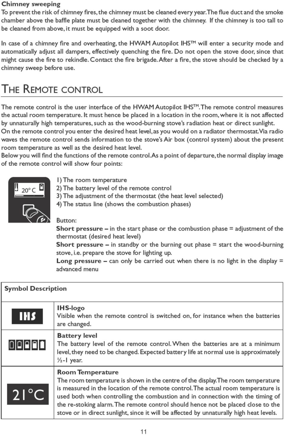
11
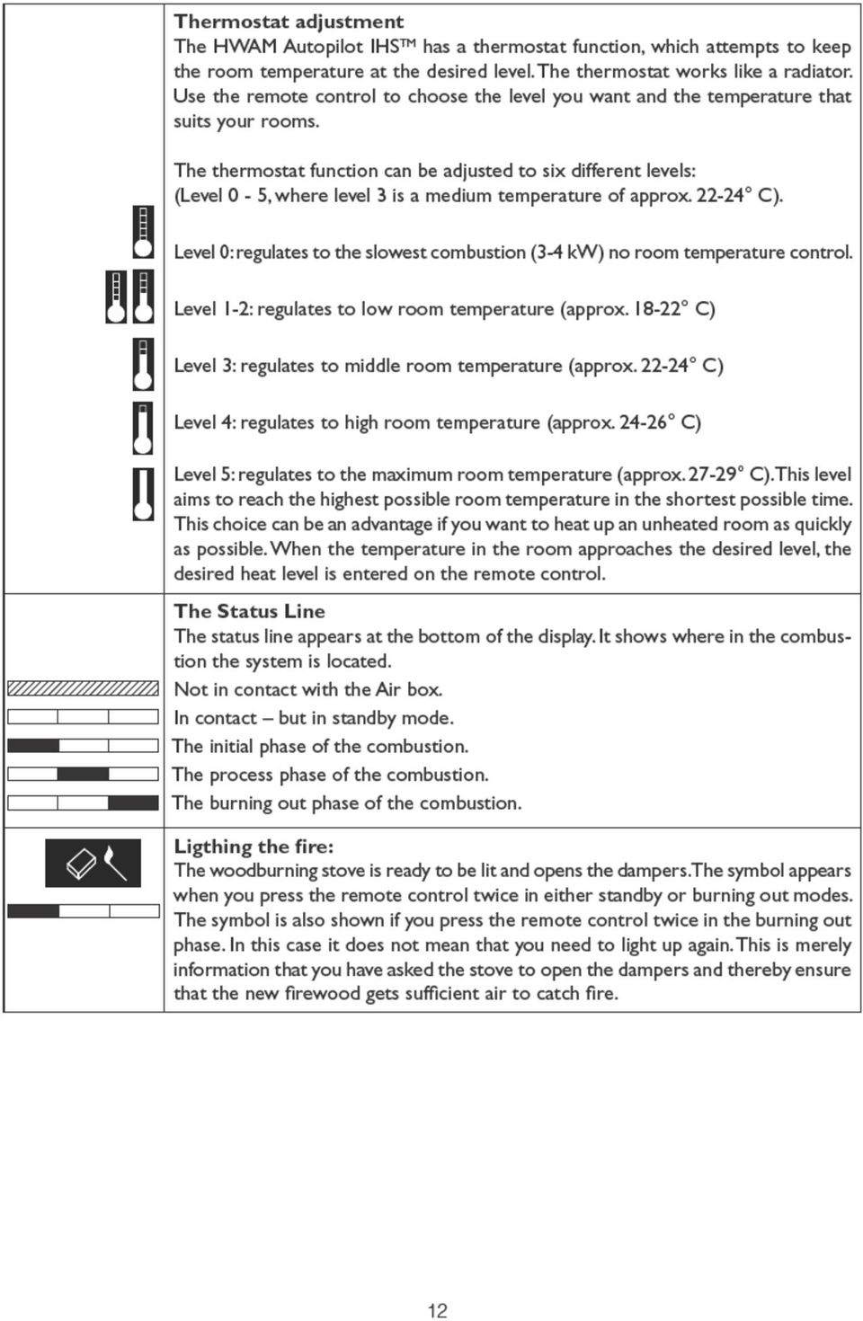
12
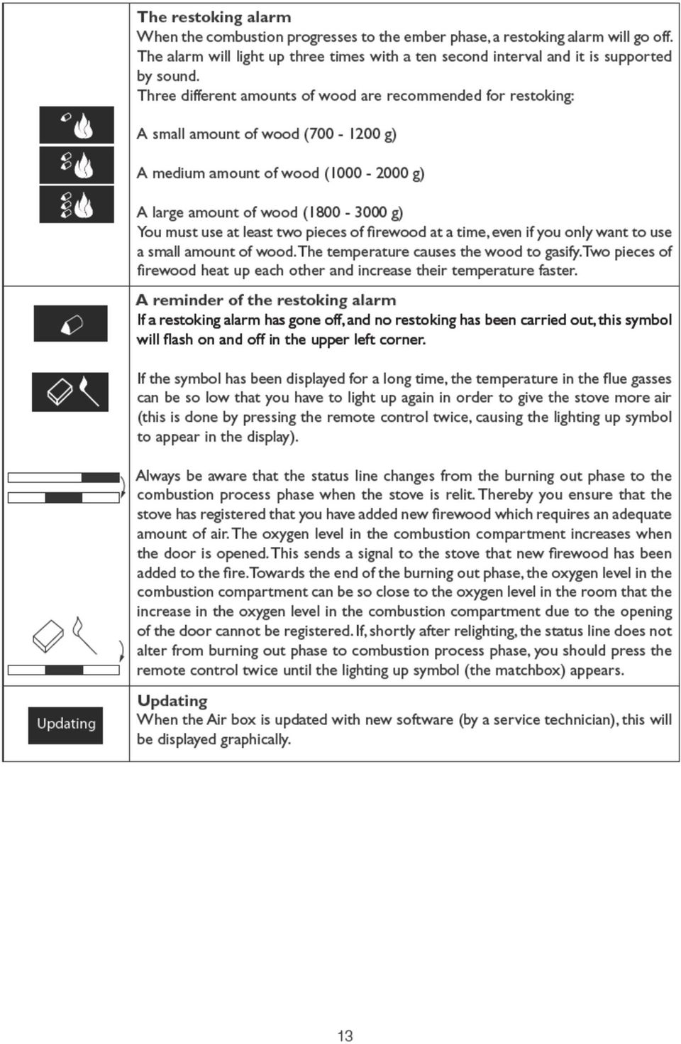
13
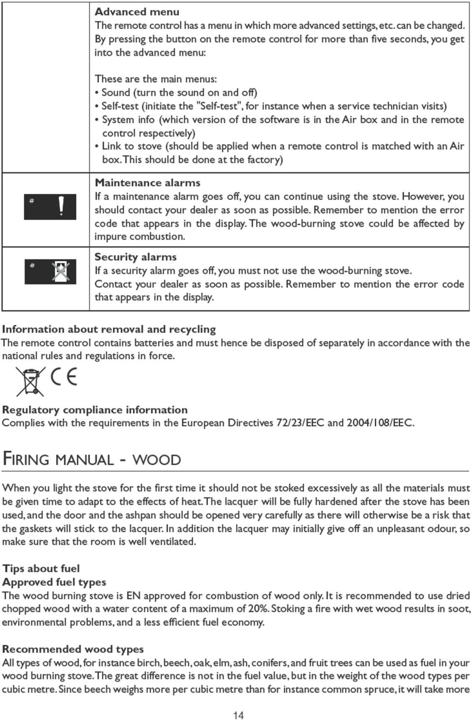
14
15 common spruce to produce the same amount of heat that you would get from a cubic metre of beech. Banned fuel types It is not allowed to stoke a fire with the following: printed matter, plywood, plastic, rubber, fluid fuels, and rubbish such as milk cartons, lacquered wood or impregnated wood and fossil fuels. The reason that you should not apply any of the above is that during combustion they develop substances that are health hazardous and harmful to the environment. These substances could also damage your wood burning stove and chimney, rendering the product warranty void. Storage of wood The wood s water content of a maximum of 20% is reached by storing the wood for a minimum of one year, preferably outdoors in an open shed exposed to sun and wind. The wood must be dry (max. 20% water contents) before it is stored indoors. It is recommended that kindling wood is stored indoors for a couple of days prior to use. Recommended dimensions The dimensions of the fuel are important to good combustion. The dimensions should be as follows: Fuel type Length in cm Diameter in cm Wood for kindling a fire (finely chopped) Chopped wood Lighting Up A successful combustion process requires that the wood is lit in the right way. A cold stove and a cold chimney challenge the combustion process. It is important to achieve a high flue gas temperature quickly. Only at temperatures around 350 C will environmentally friendly combustion take place. Place two pieces of wood (5-8 cm in diameter) horizontally in the bottom of the combustion compartment. Place 5-8 pieces of kindling randomly on top. Place two fire-lighters in between the top layers of kindling. Press the remote control twice to activate the symbol of lighting up. Light up the fire-lighters and close the stove door. Adjust the temperature selection mechanism on the remote control to the desired heat level. If the desired flue gas temperature of 350 C has not been achieved within 15 minutes, the remote control will activate a re-stoking alarm even if there still might be wood and flames in the combustion compartment. The re-stoking alarm can seem misplaced, but it is activated because the temperature climbs too slowly. Re-stoking with small pieces of kindling wood can often result in a faster increase in temperature. HWAM Autopilot IHS TM closes all three air dampers when the stove is in standby mode. This prevents hot air from the room to enter the chimney (heat loss). This might on the other hand result in a very cold chimney when the stove is lit. In certain cases it is necessary to assist the draught in the chimney by burning a couple of newspaper pages on top of the wood ready to be lit. Read more on com about the function of the chimney. Important! The ashpan must not be opened when lighting up. It must always be closed when the stove is in use. Otherwise the stove s intelligent control system does not function. The door should only be opened when lighting up, when restoking, and when cleaning the stove. The Thermostat Function The HWAM Autopilot IHS TM will in general have an environmentally friendly combustion and adapt to the desired room temperature. The thermostat function is designed as a radiator valve. The user enters 15

16
17 If these limits are exceeded, the stove will no longer be covered by the factory guarantee, and it may also become damaged due to excessive heat. The stove has been approved for intermittent use. Typical re-firing interval Typical re-firing interval at nominal performance Wood: 45 min Long burning times You achieve the slowest combustion by setting the desired room temperature at level 0. At this level the combustion takes place with the lowest possible flue gas temperature and the ember phase will be drawn out as long as possible. How to achieve the best combustion The HWAM Autopilot IHS TM is purposely designed to generate the cleanest and the most economical combustion. A good combustion is achieved when the fire gets the right amount of oxygen supply at the right time and place in the combustion chamber. The HWAM Autopilot IHS TM allows for variations in external circumstances. Nevertheless, it is important to use clean and dry wood (humidity approx %). Read more on Cleaning the glass We recommend wiping the glass after a fire. This is best done using a paper towel. Types of fuel The stove may be damaged by very high temperatures and the glass may turn white, for example. This can be avoided by never allowing the stove to burn with the ashpan open and taking great care with types of fuel that develop excessive heat, such as briquettes. If the flue gas temperature exceeds 580 o C, the HWAM Autopilot IHS TM will revert to safety adjustments and automatically turn down the air valves to avoid overheating. When the temperature is reduced to 450 o C, the normal functions apply again. It is recommended that you use birch or beech wood that has been chopped and stored for at least one year in an open shed exposed to sun and wind. The wood must be dry (max. 20% water contents) before it is stored indoors. It is recommended that kindling wood is stored indoors for a couple of days prior to use. Briquettes give off a lot of heat. Certain types expand considerably, thus causing an uncontrollable combustion. Coal burns at a high temperature and makes a lot of soot. Coal must be burned using the coal insert. Not suitable for fuel in these models. Coke burns at a high temperature and makes a lot of soot. Coke must be burned using the coal insert. Coke causes severe wear and tear to stove and combustion chamber and, consequently, this considerably reduces the life expectancy of the stove and chimney. Not suitable for fuel in these models. The stove is EN approved for firing wood only. No particle board, lacquered, painted or treated wood, plastics, or rubber may be burned. 17

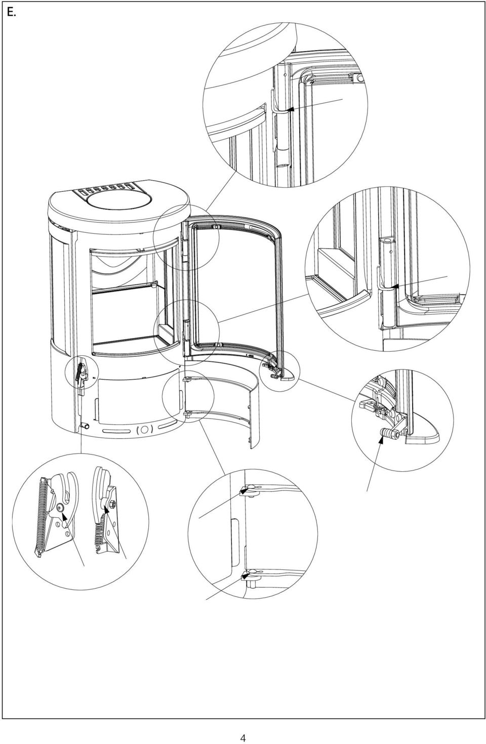
18 Maintenance Cleaning Any maintenance of the stove should only be carried out when it is cold. Daily maintenance is limited to vacuum cleaning the stove externally, using the soft brush attachment. You can also dust the stove using a dry, soft cloth or brush. But remember, only when the stove is cold. Do not use water, spirit or any other kind of cleaner, as this will damage the lacquer. Once a year, the stove should be thoroughly serviced. The combustion chamber should be cleared of ashes and soot. The hinges and the closing hook must be greased with liquid copper fat spray (heat-resistant up to 1100 degrees Celsius), see drawing E. Lift the door approx. ½ cm and spray copper fat onto the hinge leaf. Service inspection Your stove should be given a thorough, preventive inspection once every two years. This includes: Thorough cleaning of the stove. Checking gaskets. Replace gaskets if they are not intact or have softened. Checking of heat insulating material and possibly replacement. Lubricating the hinges and the locking hook with cobber grease (drawing E). All service checks must be performed by an authorised fitter. Use only original spare parts. Inside cleaning The smoke shelf and baffle plate is to be removed from the stove before cleaning. (Drawing D) Lift the smoke shelf (1) up and a little forward, so it is detached from the uppermost rear plate (2). The smoke shelf can now be lowered and removed. Lift the baffle plate (3) up a little and move it forward until it is detached from the hooks in each side. Ashes The ash pan is best emptied by pulling a waste bag over the pan, tipping it and then carefully pulling it out of the bag. Ashes are disposed of via the domestic waste collection. Please note that there may be embers in the ashes for up to 24 hours after the fire has gone out! Insulation The efficient, but porous insulation of the combustion chamber may, in time, become worn and damaged. Cracks in the insulation have no effect on the efficiency of the stove. The insulation should be replaced, however, when it is reduced to less than half the original thickness due to wear and tear. Door/glass A sooty glass door can easily be cleaned with a piece of moist kitchen roll dipped in ash. Go about it in vertical movements (up and down). Follow up with a dry piece of kitchen roll. Check frequently to ensure that seals in the door and ash pan are intact and not brittle. Failing this, they should be replaced. Use original seals only. Surface The surface normally requires no treatment. Any damage to the coating may be remedied using a Senotherm spray. Guarantee The guarantee does not cover damage due to insufficient maintenance! 18
, see drawing E. Lift the door approx.")
19 Maintenance Alarms If a maintenance alarm goes off, you can continue using the wood-burning stove, but contact your dealer as soon as possible. Your stove could be affected by impure combustion. Operational problems Blackened glass The wood is too damp. Only use wood stored for at least 12 months under cover and with a moisture level not exceeding 20% RH. Faulty seal in door. Fit new seal. Smoke in the room when opening door The grate in the chimney may be closed. Open the grate. Insufficient chimney draft. See section on chimney or contact chimney sweep. Soot door leaking or dislodged. Replace or refit. Never open the door when there are still flames on the wood. Uncontrollable combustion Faulty seal in door or ash pan. Fit new seal. Safety Alarms In case the safety alarms go off, you must not use the stove. Contact your dealer as soon as possible. At interruptions that you cannot yourself rectify, you should contact the dealer. Declaration of Performance The DoP can be downloaded from our website via the following links: HWAM 2610 with Autopilot IHS TM : HWAM 2620 with Autopilot IHS TM : HWAM 2630 with Autopilot IHS TM : HWAM 2640 with Autopilot IHS TM :

20
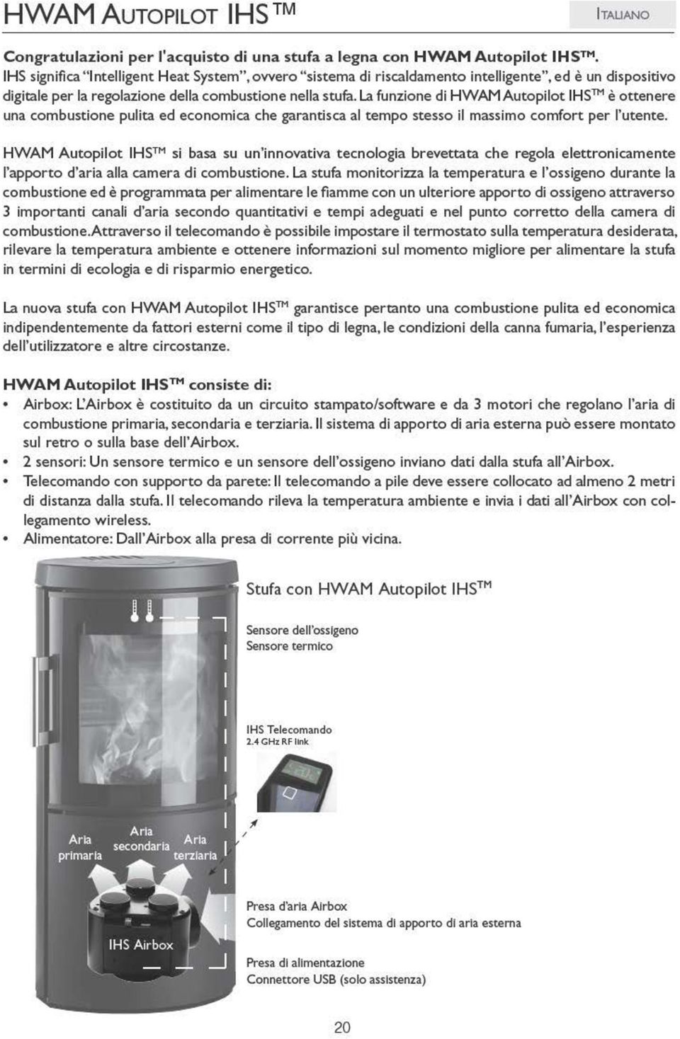
21 Istruzioni per l installazione Norme di legislazione ambientale L'installazione delle stufe HWAM deve sempre avvenire secondo le prescrizioni di legge. È sempre bene consigliarsi con chi ha installato la canna fumaria. Requisiti del locale di installazione È necessario un apporto costante di aria di combustione pulita nel locale di installazione della stufa. La stufa consuma circa m 3 d aria ogni ora. A titolo puramente indicativo, una moderna cappa per cucina aspira fino a 1000 m 3 d aria l'ora. A tale fine una finestra apribile o una valvola regolabile sono considerate sufficienti, ma è possibile anche collegare alla stufa un sistema di areazione. La valvola/griglia dell aria deve essere collocata in modo da non essere ostruita. Ricordare che non tutto il vetro è termoresistente. Pertanto, in alcuni casi, le pareti di vetro dovranno essere considerate infiammabili. Per la corretta distanza da una parete di vetro rivolgersi allo spazzacamino di zona o al fabbricante del vetro. Basamento della stufa Prima di installare la stufa ci si deve assicurare che il pavimento possa sopportare il peso della stufa e della canna fumaria. Il peso della stufa canna fumaria si calcola a secondo della dimensione e dell'altezza. Specifiche tecniche Modello Peso Altezza Larghezza Profondità HWAM 2610c/2620m con basamento 66 kg 73,0 cm 43,0 cm 36,9 cm HWAM 2610c/2620c con staffa per montaggio a parete 64 kg 70,0 cm 43,0 cm 40,4 cm HWAM 2610m/2620m con basamento 64 kg 73,0 cm 43,0 cm 36,9 cm HWAM 2610m/2620m con staffa 62 kg 70,0 cm 43,0 cm 40,4 cm per montaggio a parete HWAM 2630c/2640c 75 kg 100,0 cm 43,0 cm 36,9 cm HWAM 2630m/2640m 73 kg 100,0 cm 43,0 cm 36,9 cm Distanza da materiale infiammabile La stufa HWAM deve essere sempre messa su un pavimento ignifugo. Se la si pone su pavimenti in legno o simili, questi si devono coprire con piastre di materiale resistente al calore. Se la stufa HWAM 2610/2620 viene collocata su un pavimento in materiale infiammabile, montarla sempre al di sopra di un plinto, anche nel caso in cui il pavimento sia ricoperto da un materiale non infiammabile (come una piastra di vetro o acciaio). Il plinto è un accessorio. Per ulteriori informazioni, contattare il proprio rivenditore HWAM. Disegno A HWAM 2610 HWAM 2630 HWAM 2620 HWAM Distanza consigliata da parete in muratura 10 cm 10 cm 1. Parete dietro, infiammabile 19 cm 19 cm 2. Parete di lato, infiammabile 36 cm 36 cm 1. Parete laterale in muratura, posizionamento in angolo 34 cm* 20 cm* 3. Distanza mobili di fronte 80 cm 80 cm *Le dimensioni per il posizionamento in angolo sono indicative. Per ulteriori informazioni, contattare il rivenditore. In caso di installazione a parete, HWAM 2610/2620 deve essere appesa ad almeno 3 cm di distanza dal pavimento, se questo è realizzato in materiale infiammabile. 21
22 Prestare attenzione a eventuali normative circa la distanza tra parete e tubo di uscita fumi. Stabilire la distanza dal muro in modo da consentire l accesso all Autopilot IHS TM a fini di manutenzione. La stufa con staffa a parete può essere montata alla parete en muratura, ma in tal caso è necessario abbassare la stufa per poter intervenire sull Autopilot IHS TM. Requisiti della canna fumaria L'altezza della canna fumaria deve consentire un buon tiraggio. Il tiraggio nominale è di 12 Pa. Il diametro minimo della canna fumaria deve essere di 150 mm e questa deve essere sempre provvista di uno sportello per la pulizia. Il tubo di uscita fumi e la canna fumaria devono sempre essere adatti alla stufa Per ulteriori informazioni, rivolgersi al rivenditore HWAM. Modifica dell uscita fumi da superiore a posteriore (Disegno F) 1. Sollevare il top di ghisa (1) dalla stufa. 2. Svitare il pannello posteriore della stufa allentando le 2 viti (2). 3. Smontare la piastrina di copertura (3). 4. Svitare l anello di uscita fumi (4) e avvitarlo quindi sul retro della stufa. 5. I cavi, che adesso sono più lunghi, devono essere ripiegati con attenzione e fissati per mezzo dei bulloni appositi (5). 6. Rompere l inserto (6) sul pannello posteriore e riavvitare il pannello posteriore sulla stufa. Nel montare il pannello posteriore fare attenzione a non schiacciare i cavi. 7. Avvitare a questo punto la piastrina di copertura (3) sul top della stufa. 8. Applicare il top di ghisa (1) sulla stufa. 9. Posare il coperchio di ghisa (7) sul foro al centro del top di ghisa. Collegamento alla canna fumaria Tutte le stufe della serie hanno lo scarico fumi superiore o posteriore. Possono essere montate con una canna fumaria in acciaio omologata o collegate a una canna fumaria in muratura. Sezione verticale della canna fumaria (Disegno B e C): B: Uscita del fumo superiore C: Uscita del fumo posteriore Canna fumaria (9) in acciaio. Gomito HWAM (10) con isp.e valvola. Supporti murati (11) della canna fumaria. Foro nel muro (12). Combacia con l'entrata in canna fumaria. Rosetta murale (13). Nasconde le imperfezioni. Montaggio (14). Canali del fumo (15) della stufa HWAM. Valvola di regolazione (16) nel tubo del fumo. Sportelletto di pulizia (17). Alloggiamento delle parti singole Prima di installare la stufa, occorre accertarsi che tutti i suoi componenti siano posizionati correttamente. Sezione verticale delle stufe a legna HWAM (Disegno B): Lo scudo dei fumi (5): deve appoggiarsi alla piastra posteriore e sul supporto più alto davanti alla camera di combustione. Il deflettore (6): è sospeso su due ganci, uno per lato, nella parte più alta della camera di combustione. Per montare il deflettore, sollevarlo sopra la camera di combustione, quindi spingerlo indietro fino a quando si trova sui due ganci. Quando la stufa è installata, la protezione per il trasporto viene 22
23 rimossa. Sollevare lo scudo dei fumi in alto e in avanti. Quindi abbassarlo e rimuoverlo dalla camera di combustione. Successivamente la protezione per il trasporto viene piegata in basso/in avanti fino alla posizione verticale. La piastra inferiore in ghisa (8): deve trovarsi in posizione orizzontale sul fondo della camera di combustione. Collegamento e messa a punto di HWAM Autopilot IHS TM 1. Collegare l alimentatore a) a una normale presa della corrente da 230 V e b) all Airbox nel vano portalegna sotto la camera di combustione (introdurre l alimentatore nel traferro in basso tra il pannello laterale e il pannello posteriore, sul lato sinistro della stufa, guardando dal lato anteriore). Sull Airbox è indicato il punto in cui introdurre la spina. Vedere la fotografia del connettore di alimentazione sull Airbox. Airbox senza alimentatore Airbox con alimentatore 2. Inserire 3 pile AA nel telecomando. Quando il logo IHS scompare dal display, il telecomando è pronto per l uso. 3. Il telecomando e la stufa devono essere connessi l uno all altra (operazione eseguita in fabbrica). Se la riga di stato nella parte inferiore del display è pronta (vuota) ( ) e suddivisa in 3 campi, la stufa e il telecomando sono connessi. Se la riga di stato appare ombreggiata ( ), il telecomando e la stufa non sono connessi fra loro. Stabilire la connessione tenendo premuto il pulsante (display non illuminato) fino a visualizzare il menu avanzato. Premere brevemente e ripetutamente il pulsante fino ad evidenziare il testo "Link to stove" (Connetti alla stufa) e attendere che venga inserito in questo menu. Premere brevemente e ripetutamente il pulsante fino ad evidenziare il testo "Connect" (Connetti) e attendere di nuovo. Quando sul display viene visualizzato il testo "Please cycle stove power" (Riavviare l alimentazione elettrica della stufa) interrompere e riavviare la corrente dell Airbox. Quindi premere nuovamente il pulsante. Se il display visualizza il messaggio "Connected to stove" (Connesso alla stufa), la stufa e il telecomando sono connessi. Premere una volta il pulsante per tornare al menu principale. Se non si preme il pulsante, il telecomando chiude automaticamente il menu e si riapre la pagina iniziale. 4. Eseguire il test autodiagnostico di HWAM Autopilot IHS TM : Il test autodiagnostico della centralina elettronica di controllo deve essere eseguito prima della prima accensione della stufa (operazione eseguita in fabbrica). È possibile eseguire la procedura autodiagnostica solo quando la stufa è fredda e in modalità di attesa (nessuna indicazione nella riga di stato ). Verificare che il display non sia attivo, in altre parole non deve essere illuminato ( ). Se il pulsante viene tenuto premuto mentre il display è illuminato, la stufa si prepara per l accensione (il display visualizza un icona che rappresenta una scatola di fiammiferi) e non sarà possibile eseguire la procedura autodiagnostica. Premere il pulsante del telecomando per circa 5 secondi per accedere al menu. Premere il tasto fino a portare il cursore in corrispondenza di "Selftest" (Test autodiagnostico). Attendere per qualche secondo l apertura del menu "Selftest". Premere il tasto fino a portare il cursore in corrispondenza di "Engage" (Avvia). Dopo qualche secondo il test ha inizio. Il test autodiagnostico consente di verificare il corretto funzionamento dell apparecchio. 23
ISTRUZIONI DI MONTAGGIO LOR-THERM 105. Cod. 523.0000.102
 ISTRUZIONI DI MONTAGGIO LOR-THERM 105 Cod. 523.0000.102 Perché la garanzia sia valida, installare e utilizzare il prodotto secondo le istruzioni contenute nel presente manuale. È perciò di fondamentale
EN IT. Computer Manual. Manuale computer. Console
 Computer Manual Manuale computer EN IT Console www.energetics.eu Table of contents / Indice 1. English....................................... p. 4 2. Italiano....................................... p.
Users manual GB Instruzoni per l'uso IT
 Users manual GB Instruzoni per l'uso IT 578 006 3420 3520 3530 05.12.2014 / 97-9662 www.hwam.com 2 Table of contents, English Drawings...4-5 HWAM Autopilot IHS TM...6 Installation..........................................................
Monitor a 14 con selettore a 4 canali modello LEE-128M4 codice 559591005. Manuale d uso
 Monitor a 14 con selettore a 4 canali modello LEE-128M4 codice 559591005 Manuale d uso Sicurezza Questo simbolo indica la presenza di tensione pericolosa non isolata all interno dell'apparecchio che può
 MANUALE UTENTE MODULO ESPANSIONE TASTI MANUALE UTENTE MANUALE UTENTE Descrizione Il modulo fornisce al telefono VOIspeed V-605 flessibilità e adattabilità, mediante l aggiunta di trenta tasti memoria facilmente
SISTEMA COMPLETO DI ILLUMINAZIONE VANO LAMPADA A LED TIPO ILV24 s. COMPARTMENT SYSTEM LIGHTING COMPLETE LED LAMP TYPE ILV24 s
 SISTEMA COMPLETO DI ILLUMINAZIONE VANO LAMPADA A LED TIPO ILV24 s COMPARTMENT SYSTEM LIGHTING COMPLETE LED LAMP TYPE ILV24 s Caratteristiche generali Mean features Lampade a bassa tensione (24Vcc) Lamps
Alimentatori per LED di segnalazione (MINILED) Power supply units for Signal LEDs (MINILED)
 Power supply units for Signal LEDs (MINILED)") Alimentatori per LED di segnalazione (MINILED) Power supply units for Signal LEDs (MINILED) Alimentatori elettronici con tensione di uscita stabilizzata per moduli LED di segnalazione. Led driver with
Alimentatori per LED di segnalazione (MINILED) Power supply units for Signal LEDs (MINILED) Alimentatori elettronici con tensione di uscita stabilizzata per moduli LED di segnalazione. Led driver with
Replacement of hose carrier chain
 3 1. Bring the boom in horizontal position and make the extension completely retract. 2. Remove the rear panel. 3. Remove the front guard on the boom hood. 4. In case of machine with basket pre-arrangement,
Manuale Manutenzione Stufe a Pellet
 Manuale Manutenzione Stufe a Pellet Le stufe prodotte dai F.lli La Cava Sas sono concepite per offrire il massimo rendimento con la minima manutenzione, tuttavia trattandosi di combustibile a base di legno,
Appendice E - Appendix E PANNELLI FOTOVOLTAICI - PHOTOVOLTAIC PANELS
 Appendice E - Appendix E PANNELLI FOTOVOLTAICI - PHOTOVOLTAIC PANELS I sistemi mod. i-léd SOLAR permettono di alimentare un carico sia in bassa tensione 12-24V DC, sia a 230v AC, tramite alimentazione
rasomuro 41_ muratura-wall istruzioni di montaggio
 raso _ muratura- istruzioni di montaggio RSOMURO PERUR IRRE cm 6 cm 7 cm 8 cm 90 cm 9 /8 7 / / 8 /8 8 /8 8 /8 / 9 /8 /8 /8 /8 /8 /8 8 /8 7 /8 RSOMURO PERUR SPINGERE cm 6 cm 7 cm 8 cm 90 cm 9 /8 7 / / 8
ATTILA ISTRUZIONI DI MONTAGGIO ED UTILIZZO
 ATTILA ISTRUZIONI DI MONTAGGIO ED UTILIZZO Gentile Cliente la ringraziamo per aver scelto un nostro prodotto e la invitiamo a leggere attentamente quando di seguito riportato -Affidare l installazione
UNI 10683. ed. Ottobre 2012
 UNI 10683 ed. Ottobre 2012 Generatori di calore alimentati a legna o altri biocombustibili solidi Potenza termica nom< 35 kw VERIFICA INSTALLAZIONE CONTROLLO (NEW) MANUTENZIONE (NEW) APPARECCHI Categorie
User Guide Guglielmo SmartClient
 User Guide Guglielmo SmartClient User Guide - Guglielmo SmartClient Version: 1.0 Guglielmo All rights reserved. All trademarks and logos referenced herein belong to their respective companies. -2- 1. Introduction
MANUALE DI ISTRUZIONI. Cronotermostato MILUX
 MANUALE DI ISTRUZIONI Cronotermostato MILUX GENERALITÁ ITA Il cronotermostato MILUX è un termostato digitale programmabile, in grado di controllare e regolare direttamente gli impianti di riscaldamento
LIBRETTO D ISTRUZIONI CONTA MONETE ELETTRONICO
 LIBRETTO D ISTRUZIONI CONTA MONETE ELETTRONICO Precauzioni non aprire la macchina senza l intervento di un tecnico specializzato; inserire la spina fino infondo nella presa accertarsi che l impianto elettrico
BODY FAT MONITOR MANUALE D USO E MANUTENZIONE USE AND MAINTENANCE BOOK
 BODY FAT MONITOR MANUALE D USO E MANUTENZIONE USE AND MAINTENANCE BOOK ATTENZIONE: Gli operatori devono leggere e capire completamente questo manuale prima di utilizzare il prodotto. ATTENTION: The operators
Compatibilità del Portale Piaggio con Internet Explorer 10 e 11. Internet Explorer 10
 Italiano: Explorer 10 pagina 1, Explorer 11 pagina 2 English: Explorer 10 page 3 and 4, Explorer 11 page 5. Compatibilità del Portale Piaggio con Internet Explorer 10 e 11 Internet Explorer 10 Con l introduzione
www.biohousing.eu.com Meno emissioni e una migliore efficienza nel riscaldamento a stufe Come riuscirci?
 www.biohousing.eu.com Meno emissioni e una migliore efficienza nel riscaldamento a stufe Come riuscirci? 1 ETA Energie Rinnovabili Verso un riscaldamento più confortevole e meno inquinante 1. Usare legna
Manuale d Istruzioni. Misuratore di Umidità Senza Spinotti Modello MO257
 Manuale d Istruzioni Misuratore di Umidità Senza Spinotti Modello MO257 Introduzione Congratulazioni per aver acquistato il Misuratore di Umidità Senza Spinotti MO257 della Extech. Il sensore di umidità
MANUALE DISPLAY REMOTO CALDAIE REMOTE DISPLAY MANUAL FOR BOILERS
 MANUALE DISPLAY REMOTO CALDAIE REMOTE DISPLAY MANUAL FOR BOILERS COMPATIBILE CON - COMPATIBLE WITH LP14/20/30 SCHEDA - MOTHERBOARD 512 E SW V5 2 IT COLLEGAMENTO A MURO DELLA CONSOLE LCD - CALDAIA Collegamento
MANUALE DI USO ED INSTALLAZIONE CAMINETTI Il Canto del Fuoco _LEGNA
 MANUALE DI USO ED INSTALLAZIONE CAMINETTI Il Canto del Fuoco _LEGNA ATTENZIONE!!! Si declina ogni responsabilità relativa ad eventuali inesattezze contenute in queste istruzioni dovute ad errori di trascrizione.
MANUALE DI ISTRUZIONI TAB CHART 32
 MANUALE DI ISTRUZIONI TAB CHART 32 1 INFORMAZIONI PER LA SICUREZZA Vi preghiamo di leggere e seguire attentamente le istruzioni contenute in questo manuale. La mancata ottemperanza alle istruzioni potrebbe
Istruzioni per lo smontaggio delle Lancette; smontaggio quadrante e la regolazione della lancetta dei minuti.
 Istruzioni per lo smontaggio delle Lancette; smontaggio quadrante e la regolazione della lancetta dei minuti. Instructions to remove hands, remove dial and adjust the minute hand. 2 I. Removing hands.
MANUALE D'USO E PRIMA CONFIGURAZIONE. Telecamera IP Wireless
 MANUALE D'USO E PRIMA CONFIGURAZIONE Telecamera IP Wireless Modello 090-IPW G.S.A. Elettronica www.gsaelettronica.com pag. 1 Indice Precauzioni... Pag. 3 Avvertenze e Note... Pag. 4 Software e collegamenti....
Rilevatore portatile di monossido di
 MANUALE UTENTE Rilevatore portatile di monossido di carbonio (CO) Modello CO40 Introduzione Congratulazioni per aver scelto il modello CO40 di Extech Instruments. Il CO40 rileva simultaneamente la concentrazione
INFORMAZIONE AGLI UTENTI DI APPARECCHIATURE DOMESTICHE O PROFESSIONALI
 INFORMAZIONE AGLI UTENTI DI APPARECCHIATURE DOMESTICHE O PROFESSIONALI Ai sensi dell art. 13 del Decreto Legislativo 25 luglio 2005, n. 151 "Attuazione delle Direttive 2002/95/CE, 2002/96/CE e 2003/108/CE,
LIBRETTO D ISTRUZIONI MACCHINA PRODUTTRICE DI GHIACCIO
 LIBRETTO D ISTRUZIONI MACCHINA PRODUTTRICE DI GHIACCIO 1 Gent.li clienti, grazie per aver acquistato la macchina produttrice di ghiaccio portatile. Per un uso corretto e sicuro vi preghiamo di leggere
quick guide guida rapida J.touch hydromassage bath remote control telecomando per vasche idromassaggio
 quick guide guida rapida hydromassage bath remote control telecomando per vasche idromassaggio getting started operazioni preliminari 3 4 5 switch on the remote control by holding the on/off key; turn
www.vola-instruments.net DISTANCE METER
 www.vola-instruments.net LASER www DISTANCE METER 900 INDICE: MESSA IN FUNZIONE 4 USO 6 SPECIFICHE TECNICHE 8 MENU / SETTAGGI 9 CODICI 18 CONDIZIONI PER LA MISURAZIONE 19 ISTRUZIONI DI SICUREZZA 20 3
WWW.TINYLOC.COM CUSTOMER SERVICE GPS/ RADIOTRACKING DOG COLLAR. T. (+34) 937 907 971 F. (+34) 937 571 329 sales@tinyloc.com
 937 907 971 F. (+34) 937 571 329 sales@tinyloc.com") WWW.TINYLOC.COM CUSTOMER SERVICE T. (+34) 937 907 971 F. (+34) 937 571 329 sales@tinyloc.com GPS/ RADIOTRACKING DOG COLLAR MANUALE DI ISTRUZIONI ACCENSIONE / SPEGNERE DEL TAG HOUND Finder GPS Il TAG HOUND
WWW.TINYLOC.COM CUSTOMER SERVICE T. (+34) 937 907 971 F. (+34) 937 571 329 sales@tinyloc.com GPS/ RADIOTRACKING DOG COLLAR MANUALE DI ISTRUZIONI ACCENSIONE / SPEGNERE DEL TAG HOUND Finder GPS Il TAG HOUND
RIPETITORE DI SEGNALE WIRELESS PER SISTEMA VIA RADIO ART. 45RPT000
 RIPETITORE DI SEGNALE WIRELESS PER SISTEMA VIA RADIO ART. 45RPT000 Leggere questo manuale prima dell uso e conservarlo per consultazioni future 1 DESCRIZIONE GENERALE L espansore senza fili è un modulo
PANNELLO REMOTO PER BARRIERE 48BFC000 E 48BFC001
 PANNELLO REMOTO PER BARRIERE 48BFC000 E 48BFC001 ART.48BFA000 Leggere questo manuale prima dell uso e conservarlo per consultazioni future 1 CARATTERISTICHE GENERALI Il terminale 48BFA000 permette di
Registratore Dati Umidità e Temperatura
 Manuale d'istruzioni Registratore Dati Umidità e Temperatura Modello RHT Introduzione Congratulazioni per aver acquistato questo Registratore Dati di Temperatura e Umidità. Con questo strumento, si possono
DT - 7225 PIR INTELLIGENTE ANTI INTRUSIONE
 DT - 7225 PIR INTELLIGENTE ANTI INTRUSIONE Manuale d uso SOMMARIO Precauzioni.....pag. 2 Avvertenze e Note.. pag. 3 Caratteristiche.. pag. 4 Installazione... pag. 5 Dichiarazione Conformità... pag. 6 Skynet
Consolle DESIGN ENZO BERTI
 DESIGN ENZO BERTI Consolle 160-210 - 260 cm / 63-82,67-102,36 in 71,5 cm / 28,15 in 45 cm / 17,71 in - Consolle 160 x 45 cm Peso netto: 190 kg Peso lordo (con imballo): 230 kg - Consolle 210 x 45 cm Peso
S3 Turbo Caldaia a legna. S3 Turbo ORA ANCHE CON SONDA LAMBDA A BANDA LARGA E SERVOMOTORI. www.froeling.com
 S3 Turbo Caldaia a legna S3 Turbo ORA ANCHE CON SONDA LAMBDA A BANDA LARGA E SERVOMOTORI www.froeling.com Un marchio di eccellenza Froling si occupa da oltre cinquant anni dell utilizzo efficiente del
CONFIGURATION MANUAL
 RELAY PROTOCOL CONFIGURATION TYPE CONFIGURATION MANUAL Copyright 2010 Data 18.06.2013 Rev. 1 Pag. 1 of 15 1. ENG General connection information for the IEC 61850 board 3 2. ENG Steps to retrieve and connect
turboinwall Caldaie murali a gas ad alto rendimento per riscaldamento e produzione di acqua calda. Per installazioni a incasso.
 turboinwall Caldaie murali a gas ad alto rendimento per riscaldamento e produzione di acqua calda. Per installazioni a incasso. turboinwall turboinwall Il calore... a scomparsa La tecnologia arriva in
Easy Lock. Mod. DPN13PG Mod. DPN18PG V.2 LEGGERE ATTENTAMENTE LE ISTRUZIONI PRIMA DELL USO E CONSERVARLE IN CASO DI NECESSITA PAG. 2 PAG.
 Easy Lock Mod. DPN13PG Mod. DPN18PG PIN V.2! LEGGERE ATTENTAMENTE LE ISTRUZIONI PRIMA DELL USO E CONSERVARLE IN CASO DI NECESSITA GUIDA ALL USO MANUTENZIONE PAG. 2 PAG. 4 GUIDA ALL INSTALLAZIONE PAG. 8
INNESTO DELLE LAMELLE A TELAIO CHIUSO CON COMPENSAZIONE RAPIDA COUPLING OF SLATS IN CLOSED FRAME WITH RAPID ADJUSTMENT
 INNESTO DELLE LAMELLE A TELAIO CHIUSO CON COMPENSAZIONE RAPIDA Per la versione LASISTAS 54 CML è disponibile la compensazione rapida sia superiore che inferiore, mediante l inserimento rapido delle mezze
STUFA CERAMICA 2000 Watt. mod. SQ 134
 STUFA CERAMICA 2000 Watt mod. SQ 134 manuale d istruzioni European Standard Quality Consigliamo di leggere attentamente il presente manuale d istruzioni prima di procedere nell utilizzo dell apparecchio
PINNER Elettrodi di carica
 SIMCO (Nederland) B.V. Postbus 71 NL-7240 AB Lochem Telefoon + 31-(0)573-288333 Telefax + 31-(0)573-257319 E-mail general@simco-ion.nl Internet http://www.simco-ion.nl Traderegister Apeldoorn No. 08046136
Istruzioni per l uso Unità a schede di memoria
 Istruzioni per l uso Unità a schede di memoria Modello n. AJ- E AJ-PCD10 Collegare l'unità a schede di memoria al personal computer prima di installare il software P2 nel computer dal CD di installazione.
Igro-Termometro di Precisione Modello RH490
 Manuale d Istruzioni Igro-Termometro di Precisione Modello RH490 Introduzione Congratulazioni per aver acquistato l Igro-Termometro di Precisione Extech RH490. Questo di dispositivo misura Umidità, Temperatura
La vita domestica di tutti i giorni ci vede molto esigenti nei confronti di televisori e sistemi audio. La serie UPPLEVA viene sottoposta a rigorosi
 UPPLEVA La vita domestica di tutti i giorni ci vede molto esigenti nei confronti di televisori e sistemi audio. La serie UPPLEVA viene sottoposta a rigorosi test che ci permettono di garantirne la conformità
CRUZPRO ECOSCANDAGLIO D110
 CRUZPRO ECOSCANDAGLIO D110 Il D110 è un misuratore digitale compatto di profondità. Il D110 usa il segnale DSP (Digital Signal Processing) per avere una lettura attendibile della profondità da 1.2 a 1000
RISCALDAMENTO A BIOMASSA NORWOOD 34 CALDAIA A PELLET. Certificato EN 303-5 Classe 5 Il riscaldamento ecologico che offre risparmio e comfort
 PANTONE Warm Red CVC PANTONE Black 6 CVC RISCALDAMENTO A BIOMASSA CALDAIA A PELLET NORWOOD 34 Certificato EN 303-5 Classe 5 Il riscaldamento ecologico che offre risparmio e comfort NORWOOD 34 LA CADAIA
1 Menu utente. Fratelli La Cava Sas Manuale Programmazione Stufe Pag 1
 Fratelli La Cava Sas Manuale Programmazione Stufe Pag 1 IL MENU Con pressione sul tasto P3 (MENU) si accede al menu. Questo è suddiviso in varie voci e livelli che permettono di accedere alle impostazioni
WWW.GRUPPOMARUCCIA.COM
 WWW.GRUPPOMARUCCIA.COM ISTRUZIONI DI MONTAGGIO P10249 CABINA IDROMASSAGGIO MULTIFUNZIONE CON SAUNA CM 105X105 Istruzioni di montaggio Pagina 1 INDICE 1. Preparazione 2 2. Procedura di montaggio 4 3. Pulizia
Manuale di istruzioni aspiratore di fumi e sistema di filtraggio
 Polo scientifico tecnologico Via Bovio 6 28100 Novara - NO - Italy Tel +39 0321697200 - Fax +39 0321 688515 - Email: info@etneo.com www.etneo.com Manuale di istruzioni aspiratore di fumi e sistema di filtraggio
SENSORE MAGNETICO WIRELESS ANTENNA ESTERNA MC001A Manuale
 SENSORE MAGNETICO WIRELESS ANTENNA ESTERNA MC001A Manuale GasiaShop P.Iva: 03957290616 SOMMARIO Precauzioni.....pag. 2 Avvertenze e Note.. pag. 3 Caratteristiche.. pag. 4 Connessioni...pag. 4 Dichiarazione
MANUALE DI ISTRUZIONE ED USO SCHEDE ELETTRONICHE DI FRENATURA PER MOTORI C.A. FRENOMAT-2, FRENOSTAT R
 MANUALE DI ISTRUZIONE ED USO SCHEDE ELETTRONICHE DI FRENATURA PER MOTORI C.A. FRENOMAT-2, FRENOSTAT R Utilizzo: Le schede di frenatura Frenomat2 e Frenostat sono progettate per la frenatura di motori elettrici
Guida rapida di installazione
 Configurazione 1) Collegare il Router Hamlet HRDSL108 Wireless ADSL2+ come mostrato in figura:. Router ADSL2+ Wireless Super G 108 Mbit Guida rapida di installazione Informiamo che il prodotto è stato
Guida alla configurazione Configuration Guide
 Guida alla configurazione Configuration Guide Configurazione telecamere IP con DVR analogici, compatibili IP IP cameras configuration with analog DVR, IP compatible Menu principale: Fare clic con il pulsante
MANUALE D USO POMPE CENTRIFUGHE CON SERBATOIO PER ACQUA DI CONDENSA COD. 12170027-12170013 - 12170012-12170011
 MANUALE D USO POMPE CENTRIFUGHE CON SERBATOIO PER ACQUA DI CONDENSA COD. 12170027-12170013 - 12170012-12170011 INDICE INSTALLAZIONE...3 INTERRUTTORE DI SICUREZZA...3 SCHEMA ELETTRICO...4 GRAFICI PORTATE......5
MANUALE DI ISTRUZIONI PER L INSTALLAZIONE, L USO E LA MANUTENZIONE DI: OVERHAUL HANDBOOK FOR INSTALLATION, USE AND MAINTENANCE OF:
 Sede Operativa: 27020 PARONA (PV) Italy Via Artigianato, 12 Tel. +39 0384 253136 Fax +39 0384 253574 E-mail:info@azzalinsrl.it Web site: www.azzalinsrl.it Sede Legale: 27026 GARLASCO (PV) Vicolo della
Installazione interfaccia e software di controllo mediante PC Installing the PC communication interface and control software
 Windows 7 Installazione interfaccia e software di controllo mediante PC Installing the PC communication interface and control software Contenuto del kit cod. 20046946: - Interfaccia PC-scheda (comprensiva
ISTRUZIONI PER L USO IMPIANTI A SECCO A N T A
 ISTRUZIONI PER L USO IMPIANTI A SECCO A N T A 1 ANTA DATI TECNICI Alimentazione: 230V/50Hz Modello Numero vie di spillatura Potenza installata [W] Capacità di spillatura [lt/ora] Peso [kg] Dimensioni larghezza
Nautilus Installazione Aggiornato a versione 2.4.1092
 Nautilus Installazione Aggiornato a versione 2.4.1092 IMPORTANTE: NON INSERIRE LA CHIAVE USB DI LICENZA FINO A QUANDO RICHIESTO NOTA: se sul vostro computer è già installato Nautilus 2.4, è consigliabile
Manuale di installazione ALM-W002
 Manuale di installazione ALM-W002 ALM-W002 Sirena via radio - Manuale di installazione Tutti i dati sono soggetti a modifica senza preavviso. Conforme alla Direttiva 1999/5/EC. 1. Introduzione ALM-W002
Chiudiporta nascosto a camma 900 Concealed cam door closer 900. ASSA ABLOY, the global leader in door opening solutions
 Chiudiporta nascosto a camma 900 Concealed cam door closer 900 ASSA ABLOY, the global leader in door opening solutions Chiudiporta nascosto con movimento a camma, per porte a battente In-door concealed
Manuale d uso Jump Starter
 Manuale d uso Jump Starter 1.Torcia LED di emergenza 2.Uscita 19V con indicatore LED 3.Uscita 16V con indicatore LED 4.Uscita 12V con indicatore LED 5.Uscite 12/16/19V 2A-3/5A 6.Indicatore LED capacità
Un marchio di eccellenza
 www.froeling.com Un marchio di eccellenza Froling si occupa da quasi cinquant anni dell utilizzo efficiente del legno come fonte di energia. Oggi il marchio Froling è sinonimo di moderna tecnica per il
Dichiarazione di conformità per caldaie a carica manuale
 Ufficio di contatto marchio di qualità: Moritz Dreher Neugasse 6 CH-8005 Zürich Tel.: +41 (0)44 250 88 16 Fax.: +41 (0)44 250 88 22 Email: dreher@holzenergie.ch Marchio di qualità Energia leg Svizzera
SISTEMI FUMARI FLUE SYSTEMS
 SISTEMI FUMARI FLUE SYSTEMS SCHEMA DI MONTAGGIO La THEMA INOX, con questo strumento, cerca di fornire all utilizzatore del proprio prodotto un supporto conforme alle recenti normative in materia, cercando
Disco rigido ATA. Nota: Le istruzioni online sono disponibili all indirizzo http://www.apple.com/support/doityourself/.
 Italiano Istruzioni per la sostituzione Disco rigido ATA AppleCare Attenersi rigorosamente alle istruzioni contenute nel presente documento. Il mancato rispetto delle procedure indicate può causare danni
Kit trasmissione. data transmission. Ref. 10085
 Kit trasmissione dati WIRELESS Kit for wireles data transmission Ref. 10085 MANUALE UTENTE aspetto componenti A Chiavetta USB per connesione al PC B Strumento rilavazione dati C Adattatore 1 Connettore
Manuale d Istruzioni. Tester di Successione delle Fasi e Rotazione Motore Modello 480403
 Manuale d Istruzioni Tester di Successione delle Fasi e Rotazione Motore Modello 480403 Introduzione Congratulazioni per aver acquistato il Rilevatore Rotazione Motore e Fasi della Extech Modello 480403.
dim ELETTRO ASPIRATO 22
 TRAINING DI FORMAZIONE PER TECNICI SPECIALIZZATI dim ELETTRO ASPIRATO 22 Solve problems chart INDICE Cap. 1 IL FOCOLARE N FUNZIONA. Pag. 3 Cap. 2 IL FOCOLARE È RUMOROSO. Pag. 7 Cap. 3 IL FOCOLARE È STATO
Guida. Macchina Scratch
 Pagina 1 di 22 Guida Macchina Scratch Pagina 2 di 22 Scopo Lo scopo della guida è quello di spiegare all'utente come sia possibile creare un unità da scratch con il software Nuovo AHU. La guida spiegherà
Technical Guidelines GON % Italian production. sports car oriented
 The rubber nozzle mod GON (Gas Oval Nozzle) has the intake with 210 mm x 105 mm dimensions and has been developed by WORKY in order to be more SPORTS CAR oriented. It has been studied for vehicles with
TVCC B/W MONITOR MODELLO: TBM10H
 TVCC B/W MONITOR MODELLO: TBM10H 1 2 MONITOR B/W MANUALE D USO Ed. 1 INDICE INDICE...3 IL PANNELLO FRONTALE...5 PARTE POSTERIORE...6 COLLEGAMENTI...7 AVVERTENZE...8 NOTE IMPORTANTI...8 VENTILAZIONE...8
Istruzioni di montaggio
 0 07/00 IT Per i tecnici specializzati Istruzioni di montaggio Gruppo sfiato aria SKS per collettori piani a partire dalla versione. Prego, leggere attentamente prima del montaggio Volume di fornitura
GLS-4 LED STAGE 4. Manuale del proprietario
 GLS-4 LED STAGE 4 Manuale del proprietario Grazie per aver scelto il sistema di luci GLX LED STAGE 4. Per poterne fare un uso migliore del vostro LED SYSTEM, leggere fino in fondo quanto riportato in questo
Scheda video. 2. Se il sistema è in stop, premere il pulsante di alimentazione per riattivarlo.
 Italiano Istruzioni per la sostituzione Scheda video AppleCare Attenersi rigorosamente alle istruzioni contenute nel presente documento. Il mancato rispetto delle procedure indicate può causare danni alle
Tester per Resistenza di Terra a 4 fili Modello GRT300. Manuale d'istruzioni
 Tester per Resistenza di Terra a 4 fili Modello GRT300 Manuale d'istruzioni Introduzione Congratulazioni per aver acquistato il Tester 4 per Resistenza di Terra a 4 fili della Extech. Il Modello GRT300
caldaia a pellet biodom 27
 riscaldamento a biomassa caldaia a pellet biodom 27 Il riscaldamento ecologico che offre risparmio e comfort 27 LA CALDAIA BIODOM 27 RAPPRESENTA UN MODO EFFICACE, ECONOMICO ED ECOLOGICO DI RISCALDAMENTO
Guida utente! Purificatore aria Duux
 Guida utente! Purificatore aria Duux Congratulazioni! Congratulazioni per aver acquistato un prodotto Duux! Per assicurarsi i nostri servizi online, registrare il prodotto e la garanzia su www.duux.com/register
Uscita liquido di raffreddamento per riscaldamento esterno
 Il liquido di raffreddamento del motore può essere usato per riscaldare gli elementi esterni. Questi possono essere ad esempio cassoni, cabine gru e cassette portaoggetti. Il calore viene prelevato dal
Attuatore a relè Manuale di istruzioni
 Attuatore a relè Manuale di istruzioni www.ecodhome.com 1 Sommario 3 Introduzione 4 Descrizione e specifiche prodotto 5 Installazione 6 Funzionamento 6 Garanzia 2 Introduzione SmartDHOME vi ringrazia per
MANUALE D USO POMPA NEBULIZZATRICE PER RISPARMIO ENERGETICO RW MINI PER IMPIANTI RESIDENZIALI
 MANUALE D USO POMPA NEBULIZZATRICE PER RISPARMIO ENERGETICO RW MINI PER IMPIANTI RESIDENZIALI COD. 12170070 INDICE DESCRIZIONE...3 AVVERTENZE DI SICUREZZA...3 INSTALLAZIONE E MESSA IN OPERA...3 ALIMENTAZIONE
REGISTRATION GUIDE TO RESHELL SOFTWARE
 REGISTRATION GUIDE TO RESHELL SOFTWARE INDEX: 1. GENERAL INFORMATION 2. REGISTRATION GUIDE 1. GENERAL INFORMATION This guide contains the correct procedure for entering the software page http://software.roenest.com/
Vista d'insieme del sistema. Comando del riscaldamento via radio Introduzione e vista d'insieme
 Vista d'insieme del sistema Comando del riscaldamento via radio Introduzione e vista d'insieme Indice Indice 1 Note su queste istruzioni...3 2 Introduzione...3 3 Vista d'insieme...4 4 MAX! Soluzione in
INSTALLARE PALLADIO USB DATA CABLE IN WINDOWS XP/ME/2000/98
 rev. 1.0-02/2002 Palladio USB Data Cable INSTALLARE PALLADIO USB DATA CABLE IN WINDOWS XP/ME/2000/98 (tutti i KIT, escluso KIT MOTOROLA V6x-T280) La procedura di installazione del Palladio USB Data Cable
MASAJA - MASAJA INOX DESCRIZIONE PER CAPITOLATO DIMENSIONI MASAJA / MASAJA INOX 29 43 55 68 88 112
 MASAJA - MASAJA INOX Le caldaie a legna MASAJA e MASAJA INOX possono essere alimentate con tronchetti di lunghezza massima, a seconda dei modelli, da 500 a 1.060 mm. Corpo caldaia costituito da due elementidi
Portale Materiali Grafiche Tamburini. Grafiche Tamburini Materials Portal
 Portale Materiali Grafiche Tamburini Documentazione utente italiano pag. 2 Grafiche Tamburini Materials Portal English user guide page 6 pag. 1 Introduzione Il Portale Materiali è il Sistema Web di Grafiche
P/N DESCRIPTION QUANTITY
 BEFORE STARTING WORKING, PLEASE MAKE SURE THAT YOU GOT ALL THE BELOW COMPONENTS OLD PUMP NUMBER BHD2226 NEW PUMP BHD2238 AQND KIT DRE2570 CHECK S/N IT S IMPORTANT P/N DESCRIPTION QUANTITY BHD2238 or BHD2239
Pannelli radianti a infrarossi IHC in fibra di carbonio Per un calore delicato ma efficace
 3 1150 1750 W Riscaldamento elettrico 2 modelli Pannelli radianti a infrarossi IHC in fibra di carbonio Per un calore delicato ma efficace Applicazioni Il riscaldatore a infrarossi al carbonio IHC produce
Modifica del sistema di scarico. Limiti alla modifica del sistema di scarico. Limitazioni generali per tutti i tipi di motore e per i sistemi
 Limiti alla modifica del sistema di scarico Limiti alla modifica del sistema di scarico Limitazioni generali per tutti i tipi di motore e per i sistemi di scarico IMPORTANTE In generale non è consentito
Guida Utente i-help. Giuda per l utente del dispositivo i-help. Ufficio Tecnico ADiTech S.R.L. 09/11/2015 ADITECH S.R.L
 Guida Utente i-help Giuda per l utente del dispositivo i-help Ufficio Tecnico ADiTech S.R.L. 09/11/2015 ADITECH S.R.L INDIRIZZO: VIA GHINO VALENTI, 2, 60131, ANCONA (AN) TELEFONO: 071/2901262 FAX: 071/2917195
ELCART. Manuale di istruzioni/scheda tecnica SPECIFICATION
 PAGINA 1 DI 7 SPECIFICATION Customer : ELCART Applied To : Product Name : Piezo Buzzer Model Name : : Compliance with ROHS PAGINA 2 DI 7 2/7 CONTENTS 1. Scope 2. General 3. Maximum Rating 4. Electrical
Pannelli Fotovoltaici Serie ASP 60 MONTAGGIO Pannelli Fotovoltaici ASP GUIDA DI MONTAGGIO. Pannelli Fotovoltaici X 60
 Pannelli Fotovoltaici Serie ASP 60 MONTAGGIO Pannelli Fotovoltaici ASP GUIDA DI MONTAGGIO Questa guida contiene una serie di suggerimenti per installare i prodotti Abba Solar della serie ASP60 ed è rivolta
BDMPro Positioning Frame
 1 2 Di cosa si tratta La Morsa per BDMpro è uno strumento studiato per agevolare la lettura e la programmazione delle centraline con BDMpro. Vantaggi Grazie alla Morsa per BDMpro è possibile effettuare
PREXISO LASER DISTANCE METER. Manuale d uso
 PREXISO LASER DISTANCE METER Manuale d uso 1 2 3 7 6 4 5 Manuale d uso Italiano Le norme di sicurezza sono contenute nell'opuscolo allegato. Leggere attentamente le norme di sicurezza e il manuale d'uso
CALDAIE PER COMBUSTIBILI SOLIDI MODELLO SASP
 CALDAIE PER COMBUSTIBILI SOLIDI MODELLO SASP Caldaie in acciaio per la produzione di acqua calda ad inversione di fumi, funzionanti a scarti di legno, trucioli, pelet, segatura, cippati, bricchetti, gasolio,
04/2014. Mod: MICRON-48/G. Production code: UPD80 Grey
 04/2014 Mod: MICRON-48/G Production code: UPD80 Grey Model: UPD60-UPD80 Libretto di istruzioni I I Importanti nozioni di sicurezza 1. Per utilizzare correttamente l apparecchio, consigliamo una lettura
Contenuto della confezione. Elenco dei termini. Powerline Adapter
 Powerline Adapter Importante! Non esporre lo Powerline Adapter a temperature estreme. Non lasciare l apparecchio alla luce diretta del sole o in prossimità di elementi di riscaldamento. Non utilizzare
manuale d uso ALZAMALATI A BASE ED INNESTO Miglioriamo la qualità della vita www.vaimas.com
 manuale d uso ALZAMALATI A BASE ED INNESTO Indice AVVERTENZE DESCRIZIONE COMPONENTI MONTAGGIO SICUREZZA Consigli d uso MANUTENZIONE PULIZIA DEMOLIZIONI DATI TECNICI Componenti GARANZIA 02 03 04 05 05 05
LIBRETTO INSTALLAZIONE, USO E MANUTENZIONE BOX DOCCIA IDROMASSAGGIO
 LIBRETTO INSTALLAZIONE, USO E MANUTENZIONE BOX DOCCIA IDROMASSAGGIO Note importanti: L installazione deve eseguita da personale qualificato, la ditta importatrice declina ogni responsabilità in merito