VALVOLE IDRAULICHE E COMPONENTI INTEGRATI HYDRAULIC VALVES AND INTEGRATED COMPONENTS
|
|
|
- Gabriele Marra
- 5 anni fa
- Visualizzazioni
Transcript
1 VALVOLE IDRAULICHE E COMPONENTI INTEGRATI HYDRAULIC VALVES AND INTEGRATED COMPONENTS


2 CATALOGO GENERALE GENERAL CATALOGUE
3 MANAGEMENT SYSTEM CERTIFICATE Certificato no./certificate No.: AQ-ITA-ACCREDIA Data prima emissione/initial date: 14 dicembre 2015 Validità:/Valid: 14 dicembre dicembre 2021 Si certifica che il sistema di gestione di/this is to certify that the management system of LUEN S.r.l. - Sede Legale e Operativa Via Lombardia, Calvenzano (BG) - Italy È conforme ai requisiti della norma per il Sistema di Gestione Qualità/ has been found to conform to the Quality Management System standard: ISO 9001:2015 Questa certificazione è valida per il seguente campo applicativo: Progettazione, produzione e commercializzazione di valvole oleodinamiche e relativi gruppi integrati (EA: 17) This certificate is valid for the following scope: Design, manufacture and marketing of hydraulic valves and related integrated groups (EA: 17) Luogo e Data/Place and date: Vimercate (MB), 16 agosto 2018 Per l'organismo di Certificazione/ For the Certification Body DNV GL Business Assurance Via Energy Park, Vimercate (MB) - Italy Zeno Beltrami Management Representative La validità del presente Certificato è subordinata al rispetto delle condizioni contenute nel Contratto di Certificazione/ Lack of fulfilment of conditions as set out in the Certification Agreement may render this Certificate invalid. DNV GL Business Assurance Italia S.r.l., Via Energy Park, Vimercate (MB) - Italy. TEL: SISTEMA DI GESTIONE QUALITÀ QUALITY MANAGEMENT SYSTEM 2
4 INFORMAZIONI TECNICHE GENERALI GENERAL TECHNICAL INFORMATION Le informazioni sotto riportate sono di carattere puramente generale, per dettagli specifici contattare direttamente i nostri uffici. Col fine di migliorare costantemente la qualità dei nostri prodotti, ci riserviamo il diritto di modificarne in qualsiasi momento le caratteristiche senza preavviso. È responsabilità della spettabile clientela la costante verifica dei dati contenuti nei cataloghi. FLUIDO IDRAULICO Il fluido idraulico deve avere caratteristiche fisiche, lubrificanti e chimiche tali da renderlo idoneo all impiego in impianti oleodinamici, come ad esempio olio idraulico a base minerale HL DIN (Parte 1) e HLP DIN (Parte 2). Il grado di viscosità ISO-3448 viene indica to con lettere ISO VG seguite da un numero che rappresenta la viscosità cinematica MEDIA a 40 C in mm2/s o centi- Stokes cst. The information below is purely general, for specific details contact our offices directly. In order to constantly improve the quality of our products, we reserve the right to change specifications at any time without notice. The constant verification of the data contained in the catalogues is the responsibility of the clientele. HYDRAULIC FLUID Hydraulic fluid must have physical, lubricating and chemical properties suitable for use in hydraulic systems such as, for example, mineral based oil HL DIN (Part 1) and HLP DIN (Part 2). ISO-3448 viscosity class is expressed by ISO VG followed by one number representing the average kinematic viscosity at 40 C in mm2/s or centi- Stokes cst. GRADI DI VISCOSITÀ VISCOSITÀ CINEMATICA KINEMATIC VISCOSITY (cst) VISCOSITY max a 0 C media a 40 C min a 100 C CLASS max at 0 C medium at 40 C min at 100 C ISO VG ,4 ISO VG ,1 ISO VG ,0 ISO VG ,1 ISO VG ,8 ISO VG ,9 FILTRAZIONE Premessa : Una delle più frequenti cause di avarie negli impianti oleodinamici è l eccessiva contaminazione dell olio. Le particelle di impurità, soprattutto quelle dure e abrasive, usurano le superfici dei componenti oleodinamici e danneggiano le sedi di tenuta, provocando trafilamenti interni e malfunzionamenti. Per il corretto funzionamento delle valvole LuEn il livello di contaminazione massimo dell olio non deve generalmente eccedere i limiti delle classi 19/15 ISO-4406, ovvero NAS-1638 (vedi tabella), salvo eventuali prescrizioni più restrittive che troverete indicate nelle schede tecniche delle valvole interessate. Rapporto di filtrazione (3x) : è un dato che caratterizza ciascun tipo di filtro e rappresenta il rapporto tra il numero di particelle presenti prima e dopo il filtro aventi un diametro maggiore di X micron. Filtrazione assoluta (ISO-4572) : è il diametro X delle particelle più grosse alle quali corrisponde 3x>=75. Classe di contaminazione secondo ISO-4406 : viene espressa mediante 2 numeri che indicano rispettivamente la quantità di particelle con diametro superiore a 5 micron e 15 micron presenti in 1ml di olio. Classe di contaminazione secondo NAS-1638 : viene FILTRATION General information: very often the cause of malfunctions in hydraulic systems and components is found to be excessive fluid contamination. In particular the hard and abrasive particles in the fluid wear the hydraulic components and prevent the poppets from re-seating, with consequent internal leakage and system inefficiency. For the correct operation of Luen valves it is necessary to ensure that the oil contamination level does not exceed the limits given in class 19/15 ISO-4406, or NAS-1638 (see chart), unless otherwise specified in the relevant technical sheet. Filtration ratio (3x): it s the ratio between the number of particles before and after the filter with diameter larger than X micron. Absolute filtration rating (ISO-4572): it s the diameter X of the largest particles with 13x>=75. Contamination class ISO-4406: it s expressed by two scale numbers representing the number of particles larger than 5 micron and larger than 15 microns contained in 1 ml of fluid. Contamination class NAS-1638: it s expressed by one scale number representing the number of par- 3
5 espressa mediante un numero che indica la quantità di particelle di diverse dimensioni presenti in 100 ml di olio ticles of different size ranges contained in 100 ml of fluid. OIL FILTRATION RECOMMENDATIONS TYPE OF SYSTEM TYPE OF VALVE CLEANLINESS CLASS RECOMMENDED ISO 4406 : 1999 NAS 1638 ABSOLUTE FILTRATION (MICRON RATING) HIGH PRESSURE > 250 bar (3600 psi) components with LOW dirt tolerance 18 / 16 / MEDIUM HIGH PRESSURE components with moderate dirt tolerance 19 / 17 / LOW PRESSURE < 100 bar (1500 psi) components with GOOD dirt tolerance 20 / 18 / COMPONENTI DELLE VALVOLE COLLETTORI Valvole con collettore in ACCIAIO. Il collettore viene realizzato in Acciaio AVP (es.: 11SMn- Pb37) e viene protetto da ossidazione mediante trattamento superficiale di Zincatura o Fosfatazione. Valvole con collettore in ALLUMINIO. Il collettore viene realizzato in Alluminio estruso ad alta resistenza, appositamente studiato per applicazioni oleoidrauliche ad elevate pressioni di esercizio. A richiesta può essere sottoposto a trattamento di anodizzazione indurente (durezza HRw per una profondità di 2-3 micron), consentendo una miglior resistenza nei filetti dei condotti di collegamento e dei vari tappi di chiusura e regolazione. Sono idonee per impieghi dove la pressione massima indicata per ciascun tipo di valvola viene raggiunta solo occasionalmente o per impieghi a pressione ridotta continuativa. Per impieghi gravosi o nei casi dove la pressione massima ammissibile venga raggiunta frequentemente LuEn consiglia l uso di collettori in acciaio. CAVITÀ CE...N : Cavità normalizzata per cartucce. CE...L : Cavità per cartucce di disegno specifico LuEn. CE...LN : Cavità compatibile con altri costruttori. CI...LN : Cavità per valvole non a cartuccia. I particolari interni vengono assemblati direttamente sul blocco (in acciaio o alluminio). Tale soluzione consente una maggior compattezza e minori perdite di carico. Vengono utilizzati pattini in teflon per proteggere gli OR dall usura ed ottenere sempre il massimo delle prestazioni. Sono disponibili i disegni tecnici relativi alle Cavità di tipo CE. Non vengono invece forniti disegni di cavità interne del tipo CI in quanto l operazione di assemblaggio di valvole direttamente su collettore può essere effettuata unicamente nello stabilimento LuEn da personale specializzato, sotto rigorosi controlli dimensionali. VALVE COMPONENTS BODIES STEEL BODIES The bodies are made of Steel AVP (ex: 11SMnPb37) and is protected by oxidation through Galvanizing or Phosphating. ALUMINIUM BODIES. The bodies are made of high resistance extruded Aluminium, designed for high pressure hydraulic applications. For a higher hardness degree, they can be anodized upon request (hardness HRw, 2-3 micron deep). This allows a better resistance of the connecting threads and of the plugs and of the adjustment plugs.these bodies can be used in applications where the maximum pressure set for each single valve type is reached only occasionally or for applications with a continuous moderate pressure. Luen recommends steel bodies designed for heavy duties or for the applications in which the maximum pressure allowed is frequently reached. CAVITIES CE...N Normalized cavity for cartridges CE...L LuEn proprietary cartridge cavity CE...LN Cavity compatible with other manufacturers CI...LN Non cartridge valve cavity. The single parts are assembled directly on the body (in aluminium or steel). This allows a good compact design and low pressure drops. Special Teflon rings are used to protect the OR from wearing to always allow best performances. CE cavity drawings are at the customer s disposal. CI cavities are not supplied because the valves assembly directly on the bodies can be performed only at LuEn factory by specialized personnel and under strict dimensional controls. 4

6 ATTACCHI Gli attacchi filettati sono normalmente del tipo GAS cilindrico (BSPP) nelle dimensioni da 1/4" a 1"1/4. Altri tipi di attacchi filettati sono disponibili a richiesta. A disposizione una vasta gamma standard, METRI- CO, NPT, SAE, CETOP e flangiature specifiche per i modelli più diffusi di motori idraulici. CARTUCCE Di tipo avvitabile, possono venire inserite nell apposita cavità ricavata direttamente nell attuatore (cilindro, motore, pompa, ecc...) o in un blocco integrato. Sono realizzate in Acciaio AVP (es.:11smnpb37 o 36SMnPb14) oppure in Acciaio da Cementazione (es.: 16NiCr4) per i particolari interni. Tutti i particolari interni vengono trattati termicamente e sottoposti a rettifica o lappatura in modo da assicurare la massima affidabilità di resistenza meccanica e precisione dimensionale. Esternamente vengono protette da ossidazione mediante trattamenti superficiali di zincatura o fosfatazione. INSTALLAZIONE Per l installazione di VALVOLE CON COL- LETTORE, si raccomanda l utilizzo di accessori conformi con le porte del collettore stesso. Controllare visivamente il buono stato degli attacchi e usare coppie di serraggio adatte. Per l installazione di VALVO- LE A CARTUCCIA, seguire scrupolosamente la procedura sotto riportata. 1) Assicurarsi che la Cavità del collettor e sia eseguita correttamente a disegno. Deve essere pulita e senza bave di lavorazione (a). 2) Verificare che la Cartuccia non sia spor ca o in cattive condizioni. 3) Controllare il corretto posizionamento delle guarnizioni O-Ring e degli anelli antiestrusione. L O-Ring deve essere montato verso la porta a pressione più alta se vi è un solo anello antie strusione, oppure in mezzo a due anelli antiestrusione se entrambe le porte possono ricevere olio ad alta pressione. 4) Lubrificare le tenute della cartuccia con olio pulito, preferibilmente con lo stesso olio usato nell applicazione. Esso faciliterà l alloggiamento delle stesse nella cavità, senza danneggiamenti (b). Si consiglia inoltre l utilizzo di grasso antigrip paggio sulle filettature (c). 5) Avvitare la cartuccia a mano, finche si incontra l O-Ring sotto testa. L operazione dovrebbe essere eseguita con un leggero sforzo manuale, se così non fosse, potrebbe essere un segnale di esecuzione non corretta della cavità o danneggiamento delle parti (d). 6) Serrare la cartuccia con apposita chiave, usando una coppia di serraggio corretta, riportata sulla pa gina di catalogo corrispondente (e). 7) Nel caso di cartucce a solenoide, installare correttamente la bobina e serrare l apposita ghiera con una forza di serraggio adeguata. Se così non fosse, si potrebbe danneggiare il gruppo pilota. PORTS The threaded ports are usually GAS type, cylindrical (BSPP), size from 1/4 to 1 1/4. Different port sizes available upon request. A wide range of standard ports available METRIC NPT SAE - CETOP, as well as specific flanges for the most common hydraulic motors. CARTRIDGES Screw type, they can be fitted directly into the cavity in the actuator (cylinder, motor, pump, etc.) or in the integrated block. The valves are made of steel AVP (e.g.: 11SMnPb37 o 36SMnPb14) or for the internal mechanical blocks (es.: 16NiCr4). All the internal parts are thermally treated and ground or lapped to ensure the maximum reliability and resistance and dimensional accuracy. The external face is either galvanized or phosphating. INSTALLATION For the installation of VALVES WITH BODIES, it is recommended to use accessories which comply with the ports of the same body. Visually check the good condition of the ports and use suitable tightening torques. For the installation of CARTRIDGE VAL- VES, scrupulously follow the procedure below. 1) Make sure that the body Cavi ty is correctly executed according to drawing. It must be clean and without processing burrs (a). 2) Inspect the cartridge to ensure that it is in good condition and no external contaminant is present. 3) Check that O-rings and back-up ring are correctly positioned.the O-ring should be towards the higher-pressure port, if only one back-up ring is present, or between double back-up rings if both ports receive high pressure. 4) Dip the cartridge seals in clean oil preferably with the same oil used in the application. It will facilitate the housing of the same in the cavity, without damage (b). We also recommend the use of anti-seize grease on the threads (c). 5) Screw the cartridge in by hand until the O-ring is met. The operation should be performed with a slight manual effort, if not, it could be a signal of i ncorrect execution of the cavity or damage to the parts (d). 6) Tighten the cartridge with the appropriate wrench,using a correct tightening torque, shown on the corresponding catalogue page (e). 7) In the case of solenoid cartridges, correctly install the coil and tighten the ring nut with proper clamping force. If not, the pilot group may be damaged. 5
7 GUARNIZIONI O-RING Gli O-Ring vengono utilizzati per realizzare tenute statiche (quando non sussistono movimenti reciproci tra le parti) e dinamiche (quando ci si trova in presenza di movimento relativo delle parti). La scelta della dimensione ottimale dell'o-ring è fondamentale per realizzare la tenuta. Si raccomanda, in caso di necessità di sostituzione, di utilizzare gli stessi O-Ring specificati nella documentazione LuEn. Gli O-Ring vengono forniti standard con mescola NBR (nitrile-butadiene) (durezza 70 Shore A) secondo DIN ISO 1229 e sono idonei per temperature da -20 C a +100 C. Per temperature più alte, a richiesta, si raccomandano mescole diverse (es. V ton). ANELLI BACK-UP Dove risulta possibile l'espulsione degli O-Ring dalle loro sedi, a causa della pressione, vengono utilizzati : Anelli anti-estrusione Parbak (durezza 90 Shore A), Anelli di scorrimento in teflon (PTFE). Nel caso sia presente un solo anello antiestrusione, va sempre montato sul lato non in pressione della tenuta rispetto all'o-ring. MAGNETI Le bobine vengono fornite per funzionamento in servizio continuativo. L intermittenza ED di un elettromagnete è il valore percentuale del tempo di intersezione TI rispetto al tempo del ciclo completo di funzionamento TC, dove TC=TI+TR (TR tempo di riposo). ED=TI/TC * 100%. Servizio continuativo significa che tutte le bobine funzionano con ED=100% (nei limiti di temperatura specificati). La massima temperatura di esercizio per le bobine è di 125 C : la temperatura ambiente deve essere compresa tra -30 C e +50 C per consentire un corretto funzionamento. Le variazioni nella tensione di alimentazione non devono superare +/- 10% della tensione nominale. Al di fuori di questi valori non è garantito il corretto funzionamento delle cartucce. I connettori sono normalizzati DIN ISO 4400 (Hirshmann). Sono disponibili a richiesta connettori Kostal e cavi. Per il calcolo degli assorbimenti utilizzare le seguenti formule : corrente alternata : assorbimento(a) = potenza(va)/tensione(v) corrente continua : assorbimento(a) = potenza(w)/tensione(v). COLLAUDO TARATURA DELLE VALVOLE COLLAUDO Le Valvole Luen sono sottoposte a collaudi funzionali conformi alle specifiche, riportate nella relativa documentazione tecnica. Nel caso in cui le effettive e dettagliate condizioni di funzionamento dell apparecchiatura del Cliente non possano essere integralmente riproducibili nei laboratori di prova Luen, la completa idoneità all uso è responsabilità dell acquirente stesso. Test-report di collaudo, di norma, non vengono forniti da Luen. Nel caso in cui essi SEALS O-RING The sealing is achieved by means of O-Rings both for the static (when the parts don t move) and for the dynamic (when there s movement between the parts) sealing. The right dimension of the O-Ring is fundamental for the sealing. In case the O-Ring must be replaced, it is highly recommended to use exactly the models specified in the LUEn documentation. The O-Rings supplied are standard, made of an NBR compound, hardness 70 - Shore A, according to DIN ISO They are suitable for a temperature range between -20 and +100 C. In case higher temperatures are reached, it is recommended to use different compounds (e.g. Viton). These compounds are available upon request. BACK-UP RINGS In case the O-Ring is subject to expulsion from its seat due to high pressure, Parbak rings (hardness 90 Shore A) and Teflon (PTFE) rings are used. When a single Parbak ring is used, it should always be mounted on the side which is not under pressure with respect to the O-Ring. MAGNETS The coils are supplied to operate continuously. The working duty ED is the ratio between energized time TI and full cycle time TC, where TC=TI+TR (TR de-energized time). ED=TI/TC * 100% Working continuously duty means that all the coils have ED=100% (in the limits of the operating temperature). The maximum working temperature for the coils is 125 C: the ambient temperature must between -30 C and +50 C. Fluctuations in the operating voltage must not exceed +/- 10% of the nominal voltage. Exceeding this limit will result in an incorrect operation of the cartridges. Connectors are standard DIN ISO 4400 (Hirshmann). On request are available also Kostal connectors and wires.to calculate the current intensity, use the following formulas: alternate current: intensity(a)=power (VA)/tension(V) direct current: intensity(a)=power(w)/tension(v) TESTING AND VALVE CALIBRATION TESTING The Luen Valves are subjected to functional testing which comply with the specifications shown in the relative technical documentation. If the actual and detailed operating conditions of the Customer's equipment cannot be fully reproducible in the Luen test laboratories, the suitability for use is the buyer's Responsibility. Testing reports, as a rule, are not provided by Luen. If they are requested, they first must be agreed with Luen 6
8 siano richiesti, vanno concordati prima con Luen e specificati nell ordine, previa verifica di fattibilità degli stessi. TARATURA La taratura delle Valvole Luen è eseguita secondo due procedure ben distinte: STANDARD e SPECIA- LE. E dovere del Cliente specificare, al momento dell ordine, la taratura speciale richiesta. Altrimenti, la taratura delle valvole verrà eseguita con la procedura standard. In entrambi i casi, la taratura è eseguita con Olio tipo ISO VG 32 a 30 C di temperatura. TARATURA STANDARD : Le valvole sono tarate al valore di pressione standard (+/- 10 bar) indicato nella relativa pagina di catalogo. La responsabilità di un eventuale modifica del valore di settaggio, una volta in funzione la valvola, spetta al Cliente, che deve assicurarsi di non uscire dal campo di taratura corrispondente, indicato nella relativa pagina di catalogo. Dadi di bloccaggio, contro-dadi, dadi ciechi di protezione, in questo caso vengono leggermente serrati sul grano di regolazione, e non tirati a coppia. Dadi a tenuta stagna, dadi con guarnizioni, vengono semplicemente avvitati sul grano di regolazione. Non vengono serrati a battuta per lasciare la guarnizione intatta. Il serraggio a battuta con coppia di serraggio corretta è responsabilità del Cliente, dopo verifica del valore di taratura. Attenzione che, se non viene eseguito il serraggio corretto del dado, la valvola può avere trafilamenti di olio dal grano di regolazione. Tappi o cappucci di piombatura antimanomissione non vengono applicati, ma forniti a parte nell imballaggio. TARATURA SPECIALE : Le valvole sono tarate al valore di pressione (+/- 10 bar) richiesto dal Cliente al momento dell ordine. Dadi di bloccaggio, contro-dadi, dadi ciechi di protezione vengono serrati con coppia di serraggio adatta. Dadi a tenuta stagna, dadi con guarnizioni vengono avvitati a battuta e serrati con coppia di serraggio adatta. Tappi o cappucci di piombatura antimanomissione vengono applicati al grano di regolazione. In questo caso, se il Cliente necessita di modifica del valore di taratura, una volta in funzione la valvola, la responsabilità dell operazione di ri-taratura e la relativa sostituzione dei componenti di bloccaggio e piombatura, spetta al Cliente stesso. MARCATURA E STAMPIGLIATURA DELLE VALVOLE Le valvole Luen sono fornite, di norma, con marcatura per l identificazione e la rintracciabilità del prodotto. Viene eseguita con apparecchiatura laser o a punzone, a discrezione del costruttore. Se il Cliente desidera una marcatura SPECIALE, che comprende anche la NON MARCATURA, è tenuto a prendere accordi con l'ufficio commerciale e successivamen- and specified in the order, after their feasibility study. CALIBRATION The calibration of the Luen Valves is performed according to two distinct procedures: STANDARD and SPECIAL. It is the Customer's duty to specify, when ordering, the special calibration required. Otherwise, valve calibration will be performed with the standard procedure. In both cases, calibration is performed with ISO VG 32 Oil at temperature of 30 C. STANDARD CALIBRATION: The valves are calibrated at the standard pressure setting (+/- 10 bar) shown by the relevant catalogue page. The responsibility for any change in the setting value, once the valve is operating, is the Customer's responsibility, who must ensure that he does not go out of the corresponding calibration range shown on the relevant catalogue page. Locking nuts, counter-nuts, cap nuts, in this case they are slightly tightened on the adjusting screw, and not pulled together. Watertight nuts, nuts with gaskets, are simply screwed onto the adjusting screw. They are not screwed down tight to leave the gasket intact. Screwed down tight with correct tightening torque is the Client's responsibility, after verification of the calibration value. Attention: if the correct tightening of the nut is not carried out, the valve may have oil leaks from the adjusting screw.tamper proof caps are not applied but supplied separately in the package. SPECIAL CALIBRATION: The valves are calibrated at the pressure value (+/- 10 bar) requested by the Customer when ordering. Locking nuts, counter nuts, blind protection nuts are tightened with a suitable tightening torque. Watertight nuts, nuts with gaskets, are screwed down tight and tightened with a suitable tightening torque. Tamper-proof lead caps or caps are applied to the adjustment screw. In this case, once the valve is operating, if the Client needs to change the calibration value, the responsibility of the re-calibration and the relative replacement of the locking and sealing components, is the Client's responsibility. VALVE MARKING AND STAMPING The Luen valves are supplied, as a rule, with marking for product identification and traceability. It is performed with laser or punching equipment, at the discretion of the manufacturer. If the Client wants a SPECIAL marking, which also includes NON-MARKING, he is obliged to decide with the sales department and then to specify it in the order, otherwise the valves will be marked with STANDARD MARKING as in the following diagrams. 7
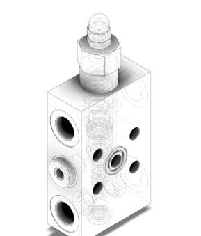
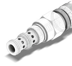
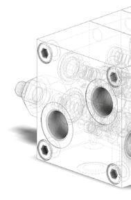
9 te a specificarlo nell ordine, altrimenti le valvole verranno marcate con MARCATURA STANDARD come negli schemi che seguono. Valvole con Collettore : La marcatura viene eseguita solamente sulla faccia principale del collettore e comprende (vedi immagine) : Logo Luen Made in Italy Codice della Valvola Lotto di produzione Sigla delle Porte Valvole a Cartuccia : La marcatura viene eseguita su una delle facce dell esagono per chiave. In questo caso, un eventuale marcatura speciale richiesta dal Cliente, deve tener conto dello spazio ridotto per l esecuzione. Essa comprende (vedi immagine) : Codice della Valvola Lotto di produzione Valves with Bodies: The marking is performed only on the main face of the body and includes (see image): Luen Logo Made in Italy Valve code Production batch Port Code Cartridge valves: The marking is performed on one of the hexagon faces by wrench. In this case, any special marking requested by the Client must consider the reduced space for execution. It includes (see image): Valve code Production batch IMBALLAGGIO E STOCCAGGIO DELLE VALVOLE Le valvole vanno conservate protette nel loro involucro termoretraibile, lontane dall'irraggiamento solare o da sorgenti di calore e di ozono (che producono un invecchiamento precoce delle guarnizioni), in un ambiente con temperature tra -20 C e +50 C. Evitare la vicinanza con motori elettrici in funzione. Di norma, eventuali parti accessorie alla valvola (bulloni, rondelle, tappi antimanomissione, particolari speciali per flangiatura) vengono forniti a parte, in quantità richiesta, in un unico contenitore. Eventuali richieste, da parte del Cliente, di imballaggio speciale devono essere concordate al momento dell ordine. PACKAGING AND STORAGE OF VALVES The valves must be kept protected in their shrink wrapping, away from solar radiation or from heat and ozone sources (which produce premature aging of the gaskets), in an environment with temperatures between -20 C and +50 C. Avoid being near running electric motors.as a rule, any valve accessory parts (bolts, washers, tamper-proof caps, special parts for flanging) are supplied separately in a single container of the requested quantity. Any Client requests for special packaging must be agreed when ordering. 8
10 INDICE GENERALE GENERAL INDEX VALVOLE DI BILANCIAMENTO E BLOCCO COUNTERBALANCE VALVES 1 VALVOLE DI MASSIMA PRESSIONE RELIEF VALVES 2 VALVOLE DI BLOCCO CHECK VALVES 3 VALVOLE REGOLATRICI DI PORTATA FLOW CONTROL VALVES 4 ELETTROVALVOLE SOLENOID VALVES 5 9
11

12 VALVOLE DI BILANCIAMENTO E BLOCCO COUNTERBALANCE VALVES
13 NOTE
14 VALVOLE DI BILANCIAMENTO E BLOCCO COUNTERBALANCE VALVES 1 VALVOLE A CARTUCCIA CARTRIDGE VALVES PAG VALVOLE A SEMPLICE EFFETTO IN LINEA SINGLE ACTING VALVES WITH IN-LINE BODY PAG VALVOLE A DOPPIO EFFETTO IN LINEA DOUBLE ACTING VALVES WITH IN-LINE BODY PAG VALVOLE CON COLLETTORE FLANGIABILE VALVES WHITH FLANGIABLE BODY PAG Control Control VALVOLE CON COLLETTORE CETOP VALVES WITH CETOP INSTALLATION PAG VALVOLE CON FLANGIATURA MOTORE MOTOR FLANGEABLE VALVES PAG VALVOLE CON FUNZIONE RIGENERATIVA VALVES WITH REGENERATIVE FUNCTION PAG
15 OWC VALVOLA BILANCIAMENTO, BLOCCO E CONTROLLO MOVIMENTO A CARTUCCIA CARATTERISTICHE PERFORMANCE Luce nominale DN 4 Rated size Portata min/max 1/25 l/min /6.6 GPM Min/max flow-rate Pressione max. di picco 450 bar PSI Max peak pressure Pressione max. di taratura 350 bar PSI Max setting pressure Rapporto di pilotaggio standard 4 : 1 Standard pilot ratio Temperatura ambiente -30 C + 50 C Room temperature Temperatura olio -30 C + 80 C Oil temperature Filtraggio consigliato 30 micron Recommended filtration Coppia di serraggio Nm Tightening torque Peso Kg Weight NOTE: La taratura deve essere 1.3 volte maggiore della pressione indotta dal carico. Valve should be set at 1.3 times load induced pressure. ESEMPIO/EXAMPLE: Pressione di lavoro max: Max working pressure: 350 bar / 1.3 = 270 bar Viscosità olio 46 cst a 50 C Oil viscosity 46 cst at 50 C
16 CARTRIDGE COUNTERBALANCE VALVES WITHOUT BODY CAVITÀ CAVITY CE.120.N ESEMPIO TIPICO DI CIRCUITO TYPICAL CIRCUIT EXAMPLE Si raccomanda l esatta esecuzione della sede The valve seat should be perfectly tooled CODICE DI ORDINAZIONE HOW TO ORDER X 0 Campo taratura / Setting range Campo taratura bar (molla colore verde) Setting range bar (green spring) Campo taratura bar (molla colore giallo) Setting range bar (yellow spring) Rapporto di pilotaggio Pilot ratios O 4 : 1 X Regolazione Adjustment Grano - Dowel Taratura standard (Q=5 l/1 ) Std. bar setting (Q=5 l/1 ) 180 bar Incr. press. - bar giro/vite Pressure rise - turn of screw (45) Taratura standard (Q=5 l/1 ) Std. bar setting (Q=5 l/1 ) 250 bar Incr. press. - bar giro/vite Pressure rise - turn of screw (75) F 7 :
17 OWC VALVOLA BILANCIAMENTO, BLOCCO E CONTROLLO MOVIMENTO A CARTUCCIA CARATTERISTICHE PERFORMANCE Luce nominale DN 10 Rated size Portata min/max 1/60 l/min /15.9 GPM Min/max flow-rate Pressione max. di picco 450 bar PSI Max peak pressure Pressione max. di taratura 350 bar PSI Max setting pressure Rapporto di pilotaggio standard 4.25 : 1 Standard pilot ratio Temperatura ambiente -30 C + 50 C Room temperature Temperatura olio -30 C + 80 C Oil temperature Filtraggio consigliato 30 micron Recommended filtration Coppia di serraggio Nm Tightening torque Peso Kg Weight NOTE: La taratura deve essere 1.3 volte maggiore della pressione indotta dal carico. Valve should be set at 1.3 times load induced pressure. ESEMPIO/EXAMPLE: Pressione di lavoro max: Max working pressure: 350 bar / 1.3 = 270 bar Viscosità olio 46 cst a 50 C Oil viscosity 46 cst at 50 C
18 CARTRIDGE COUNTERBALANCE VALVES WITHOUT BODY CAVITÀ CAVITY CE.025.N ESEMPIO TIPICO DI CIRCUITO TYPICAL CIRCUIT EXAMPLE Si raccomanda l esatta esecuzione della sede The valve seat should be perfectly tooled CODICE DI ORDINAZIONE HOW TO ORDER N X 0 Campo taratura / Setting range Campo taratura bar (molla colore verde) Setting range bar (green spring) Taratura standard (Q=5 l/1 ) Std. bar setting (Q=5 l/1 ) 180 bar Incr. press. - bar giro/vite Pressure rise - turn of screw (50) Campo taratura bar (molla colore giallo) Setting range bar (yellow spring) Taratura standard (Q=5 l/1 ) Std. bar setting (Q=5 l/1 ) 250 bar Incr. press. - bar giro/vite Pressure rise - turn of screw (90) Rapporto di pilotaggio Pilot ratios O 4.25 : 1 D 8 : 1 X Regolazione Adjustment Grano - Dowel
19 OWC-30-CC-... VALVOLA BILANCIAMENTO, BLOCCO E CONTROLLO MOVIMENTO PER CENTRO CHIUSO A CARTUCCIA CARATTERISTICHE PERFORMANCE Luce nominale DN 4 Rated size Portata min/max 1/25 l/min /6.6 GPM Min/max flow-rate Pressione max. di picco 450 bar PSI Max peak pressure Pressione max. di taratura 350 bar PSI Max setting pressure Rapporto di pilotaggio standard 4 : 1 Standard pilot ratio Temperatura ambiente -30 C + 50 C Room temperature Temperatura olio -30 C + 80 C Oil temperature Filtraggio consigliato 30 micron Recommended filtration Coppia di serraggio Nm Tightening torque Peso Kg Weight NOTE: La taratura deve essere 1.3 volte maggiore della pressione indotta dal carico. Valve should be set at 1.3 times load induced pressure. ESEMPIO/EXAMPLE: Pressione di lavoro max: Max working pressure: 350 bar / 1.3 = 270 bar Viscosità olio 46 cst a 50 C Oil viscosity 46 cst at 50 C
20 CARTRIDGE STYLE COUNTERBALANCE VALVE FOR CLOSED CENTRE SPOOL CAVITÀ CAVITY CE.120.N ESEMPIO TIPICO DI CIRCUITO TYPICAL CIRCUIT EXAMPLE Si raccomanda l esatta esecuzione della sede The valve seat should be perfectly tooled CODICE DI ORDINAZIONE HOW TO ORDER X 0 Campo taratura / Setting range Campo taratura bar (molla colore verde) Setting range bar (green spring) Campo taratura bar (molla colore giallo) Setting range bar (yellow spring) Rapporto di pilotaggio Pilot ratios O 4 : 1 X Regolazione Adjustment Grano - Dowel Taratura standard (Q=5 l/1 ) Std. bar setting (Q=5 l/1 ) 180 bar Incr. press. - bar giro/vite Pressure rise - turn of screw (45) Taratura standard (Q=5 l/1 ) Std. bar setting (Q=5 l/1 ) 250 bar Incr. press. - bar giro/vite Pressure rise - turn of screw (75) F 7 : 1 H Piombata - Sealed
21 WBC-40-CC-... VALVOLA BILANCIAMENTO, BLOCCO E CONTROLLO MOVIMENTO PER CENTRO CHIUSO A CARTUCCIA CARATTERISTICHE PERFORMANCE Luce nominale DN 10 Rated size Portata min/max 1/60 l/min /15.9 GPM Min/max flow-rate Pressione max. di picco 450 bar PSI Max peak pressure Pressione max. di taratura 350 bar PSI Max setting pressure Rapporto di pilotaggio standard 4.25 : 1 Standard pilot ratio Temperatura ambiente -30 C + 50 C Room temperature Temperatura olio -30 C + 80 C Oil temperature Filtraggio consigliato 30 micron Recommended filtration Coppia di serraggio Nm Tightening torque Peso Kg Weight NOTE: La taratura deve essere 1.3 volte maggiore della pressione indotta dal carico. Valve should be set at 1.3 times load induced pressure. ESEMPIO/EXAMPLE: Pressione di lavoro max: Max working pressure: 350 bar / 1.3 = 270 bar Viscosità olio 46 cst a 50 C Oil viscosity 46 cst at 50 C
22 CARTRIDGE STYLE COUNTERBALANCE VALVE FOR CLOSED CENTRE SPOOL CAVITÀ CAVITY CE.025.N ESEMPIO TIPICO DI CIRCUITO TYPICAL CIRCUIT EXAMPLE Si raccomanda l esatta esecuzione della sede The valve seat should be perfectly tooled CODICE DI ORDINAZIONE HOW TO ORDER X 0 Campo taratura / Setting range 498 Campo taratura bar (molla colore rosso) Setting range bar (red spring) Taratura standard (Q=5 l/1 ) Std. bar setting (Q=5 l/1 ) 250 bar Incr. press. - bar giro/vite Pressure rise - turn of screw (140) Rapporto di pilotaggio Pilot ratios O 4.25 : 1 D 8 : 1 X Regolazione Adjustment Grano - Dowel
23 WBC-40-CC-RPV VALVOLA BILANCIAMENTO, BLOCCO E CONTROLLO MOVIMENTO PER CENTRO CHIUSO A CARTUCCIA CARATTERISTICHE PERFORMANCE Luce nominale DN 10 Rated size Portata min/max 1/60 l/min /15.9 GPM Min/max flow-rate Pressione max. di picco 450 bar PSI Max peak pressure Pressione max. di taratura 350 bar PSI Max setting pressure Rapporto di pilotaggio standard 9 : 1 Standard pilot ratio Temperatura ambiente -30 C + 50 C Room temperature Temperatura olio -30 C + 80 C Oil temperature Filtraggio consigliato 30 micron Recommended filtration Coppia di serraggio Nm Tightening torque Peso Kg Weight NOTE: La taratura deve essere 1.3 volte maggiore della pressione indotta dal carico. Valve should be set at 1.3 times load induced pressure. ESEMPIO/EXAMPLE: Pressione di lavoro max: Max working pressure: 350 bar / 1.3 = 270 bar Viscosità olio 46 cst a 50 C Oil viscosity 46 cst at 50 C
24 CARTRIDGE STYLE COUNTERBALANCE VALVE FOR CLOSED CENTRE SPOOL CAVITÀ CAVITY CE.025.N ESEMPIO TIPICO DI CIRCUITO TYPICAL CIRCUIT EXAMPLE Si raccomanda l esatta esecuzione della sede The valve seat should be perfectly tooled CODICE DI ORDINAZIONE HOW TO ORDER X 0 Campo taratura / Setting range 011 Campo taratura bar (molla colore rosso) Setting range bar (red spring) Taratura standard (Q=5 l/1 ) Std. bar setting (Q=5 l/1 ) 250 bar Incr. press. - bar giro/vite Pressure rise - turn of screw (140) Rapporto di pilotaggio Pilot ratios O 9 : 1 X Regolazione Adjustment Grano - Dowel
25 A-OWC-SE-...-L-FR VALVOLA BILANCIAMENTO, BLOCCO E CONTROLLO MOVIMENTO A SEMPLICE EFFETTO CON COLLETTOREIN LINEA CARATTERISTICHE PERFORMANCE Luce nominale DN 6/8/10 Rated size Portata min/max 1/60 l/min /15.9 GPM Min/max flow-rate Pressione max. di picco 450 bar PSI Max peak pressure Pressione max. di taratura 350 bar PSI Max setting pressure Rapporto di pilotaggio standard 4.25 : 1 Standard pilot ratio Temperatura ambiente -30 C + 50 C Room temperature Temperatura olio -30 C + 80 C Oil temperature Filtraggio consigliato 30 micron Recommended filtration Coppia di serraggio Tightening torque Peso Weight NOTE: La taratura deve essere 1.3 volte maggiore della pressione indotta dal carico. Valve should be set at 1.3 times load induced pressure. ESEMPIO/EXAMPLE: Pressione di lavoro max 350 bar / 1.3 = 270 bar Max working pressure Fornitura standard valvola: corpo in acciaio. A richiesta corpo in alluminio. Steel body valves as standard, aluminium body on request Viscosità olio 46 cst a 50 C - Oil viscosity 46 cst at 50 C
26 SINGLECOUNTERBALANCE VALVE WITH IN LINE BODY ESEMPIO TIPICO DI CIRCUITO TYPICAL CIRCUIT EXAMPLE DIMENSIONI DIMENSIONS Campo taratura Setting range P Q R S Attacchi Port size V2-C2 V1-C1 GAS (BSPP) Luce nominale Rated size DN Portata max Max flow-rate l/min - GPM /4" /8" /2" CODICE DI ORDINAZIONE HOW TO ORDER N X 0 A Campo taratura / Setting range Campo taratura bar (molla colore verde) Setting range bar (green spring) Taratura standard (Q=5 l/1 ) Std. bar setting (Q=5 l/1 ) 180 bar Incr. press. - bar giro/vite Pressure rise - turn of screw (50) Campo taratura bar (molla colore giallo) Setting range bar (yellow spring) Taratura standard (Q=5 l/1 ) Std. bar setting (Q=5 l/1 ) 250 bar Incr. press. - bar giro/vite Pressure rise - turn of screw (90) Rapporto di pilotaggio Pilot ratios O 4.25 : 1 D 8 : 1 X K Regolazione Adjustment Grano - Dowel Piombata - Sealed A Collettore Body Acciaio zincato Zinc plated steel
27 A-WB-C-SE-...-L VALVOLA BILANCIAMENTO, BLOCCO E CONTROLLO MOVIMENTO A SEMPLICE EFFETTO CON COLLETTORE IN LINEA CARATTERISTICHE PERFORMANCE Luce nominale DN 6/8/10 Rated size Portata min/max 1/60 l/min /15.9 GPM Min/max flow-rate Pressione max. di picco 450 bar PSI Max peak pressure Pressione max. di taratura 350 bar PSI Max setting pressure Rapporto di pilotaggio standard 4.25 : 1 Standard pilot ratio Temperatura ambiente -30 C + 50 C Room temperature Temperatura olio -30 C + 80 C Oil temperature Filtraggio consigliato 30 micron Recommended filtration Coppia di serraggio Tightening torque Peso Weight NOTE: La taratura deve essere 1.3 volte maggiore della pressione indotta dal carico. Valve should be set at 1.3 times load induced pressure. ESEMPIO/EXAMPLE: Pressione di lavoro max 350 bar / 1.3 = 270 bar Max working pressure Fornitura standard valvola: corpo in acciaio. A richiesta corpo in alluminio. Steel body valves as standard, aluminium body on request Viscosità olio 46 cst a 50 C - Oil viscosity 46 cst at 50 C
28 SINGLE COUNTERBALANCE VALVE WITH IN LINE BODY ESEMPIO TIPICO DI CIRCUITO TYPICAL CIRCUIT EXAMPLE DIMENSIONI DIMENSIONS Campo taratura Setting range P Q R Attacchi Port size V2-C2 V1-C1 GAS (BSPP) Luce nominale Rated size DN Portata max Max flow-rate l/min - GPM /8" /2" CODICE DI ORDINAZIONE HOW TO ORDER N X 0 A Campo taratura / Setting range Campo taratura bar (molla colore verde) Setting range bar (green spring) Taratura standard (Q=5 l/1 ) Std. bar setting (Q=5 l/1 ) 180 bar Incr. press. - bar giro/vite Pressure rise - turn of screw (50) Campo taratura bar (molla colore giallo) Setting range bar (yellow spring) Taratura standard (Q=5 l/1 ) Std. bar setting (Q=5 l/1 ) 250 bar Incr. press. - bar giro/vite Pressure rise - turn of screw (90) Rapporto di pilotaggio Pilot ratios O 4.25 : 1 D 8 : X K Regolazione Adjustment Grano - Dowel Piombata - Sealed Collettore possibile in AL togliendo "A" Available aluminium body without "A" A Collettore Body Acciaio zincato Zinc plated steel
29 ...-OWC-SE-...-L-... VALVOLA BILANCIAMENTO, BLOCCO E CONTROLLO MOVIMENTO A SEMPLICE EFFETTO CON COLLETTORE IN LINEA CARATTERISTICHE PERFORMANCE Luce nominale DN 12/14 Rated size Portata min/max 1/160 l/min /42.3 GPM Min/max flow-rate Pressione max. di picco 450 bar PSI Max peak pressure Pressione max. di taratura 350 bar PSI Max setting pressure Rapporto di pilotaggio standard 6.2 : 1 Standard pilot ratio Temperatura ambiente -30 C + 50 C Room temperature Temperatura olio -30 C + 80 C Oil temperature Filtraggio consigliato Recommended filtration Coppia di serraggio Tightening torque Peso Weight NOTE: La taratura deve essere 1.3 volte maggiore della pressione indotta dal carico. Valve should be set at 1.3 times load induced pressure. ESEMPIO/EXAMPLE: Pressione di lavoro max: Max working pressure: 350 bar / 1.3 = 270 bar Viscosità olio 46 cst a 50 C Oil viscosity 46 cst at 50 C
30 SINGLE COUNTERBALANCE VALVE WITH IN LINE BODY ESEMPIO TIPICO DI CIRCUITO TYPICAL CIRCUIT EXAMPLE DIMENSIONI DIMENSIONS Campo taratura Setting range P Q R S Attacchi Port size V2-C2 V1-C1 GAS (BSPP) Luce nominale Rated size DN Portata max Max flow-rate l/min - GPM /4" " Corpo Body Acciaio Steel Acciaio Steel CODICE DI ORDINAZIONE HOW TO ORDER X 0 A Campo taratura / Setting range Campo taratura bar (molla colore giallo) Setting range bar (yellow spring) Taratura standard (Q=5 l/1 ) Std. bar setting Q=5 l/1 ) 250 bar Incr. press. - bar giro/vite Pressure rise - turn of screw (125) Rapporto di pilotaggio Pilot ratios O 6.2 : 1 G 4.1 : 1 X K Regolazione Adjustment Grano - Dowel Piombata - Sealed A Collettore Body Acciaio zincato Zinc plated steel
31 OWC-30-SE-14-L VALVOLA BILANCIAMENTO, BLOCCO E CONTROLLO MOVIMENTO A SEMPLICE EFFETTO CON COLLETTORE IN LINEA CARATTERISTICHE PERFORMANCE Luce nominale DN 6 Rated size Portata min/max 1/25 l/min /6.6 GPM Min/max flow-rate Pressione max. di picco 450 bar PSI Max peak pressure Pressione max. di taratura 350 bar PSI Max setting pressure Rapporto di pilotaggio standard 4 : 1 Standard pilot ratio Temperatura ambiente -30 C + 50 C Room temperature Temperatura olio -30 C + 80 C Oil temperature Filtraggio consigliato 30 micron Recommended filtration Coppia di serraggio Tightening torque Peso Kg Weight NOTE: La taratura deve essere 1.3 volte maggiore della pressione indotta dal carico. Valve should be set at 1.3 times load induced pressure. ESEMPIO/EXAMPLE: Pressione di lavoro max: Max working pressure: 350 bar / 1.3 = 270 bar Viscosità olio 46 cst a 50 C Oil viscosity 46 cst at 50 C
32 SINGLE COUNTERBALANCE VALVE WITH IN LINE BODY DIMENSIONI DIMENSIONS ESEMPIO TIPICO DI CIRCUITO TYPICAL CIRCUIT EXAMPLE Campo taratura Setting range Attacchi Port size V2-C2 V1-C1-PIL GAS (BSPP) Luce nominale Rated size DN Portata max Max flow-rate l/min - GPM 623 1/4" CODICE DI ORDINAZIONE HOW TO ORDER X 0 A Campo taratura / Setting range 623 Campo taratura bar (molla colore giallo) Setting range bar (yellow spring) Taratura standard (Q=5 l/1 ) Std. bar setting Q=5 l/1 ) 250 bar Incr. press. - bar giro/vite Pressure rise - turn of screw (75) Rapporto di pilotaggio Pilot ratios O 4 : 1 F 7 : 1 X Regolazione Adjustment Grano - Dowel A Collettore Body Acciaio zincato Zinc plated steel
33 A-WB-C-SE VALVOLA BILANCIAMENTO, BLOCCO E CONTROLLO MOVIMENTO CON PILOTAGGIO ESTERNO CARATTERISTICHE PERFORMANCE Luce nominale DN 6/8/10 Rated size Portata min/max 1/60 l/min /15.9 GPM Min/max flow-rate Pressione max. di picco 450 bar PSI Max peak pressure Pressione max. di taratura 350 bar PSI Max setting pressure Rapporto di pilotaggio standard 4.25 : 1 Standard pilot ratio Temperatura ambiente -30 C + 50 C Room temperature Temperatura olio -30 C + 80 C Oil temperature Filtraggio consigliato 30 micron Recommended filtration Coppia di serraggio Tightening torque Peso Weight NOTE: La taratura deve essere 1.3 volte maggiore della pressione indotta dal carico. Valve should be set at 1.3 times load induced pressure. ESEMPIO/EXAMPLE: Pressione di lavoro max 350 bar / 1.3 = 270 bar Max working pressure Fornitura standard valvola: corpo in acciaio. A richiesta corpo in alluminio. Steel body valves as standard, aluminium body on request Viscosità olio 46 cst a 50 C - Oil viscosity 46 cst at 50 C
34 COUNTERBALANCE VALVE WITH EXTERNAL PILOT ESEMPIO TIPICO DI CIRCUITO TYPICAL CIRCUIT EXAMPLE DIMENSIONI DIMENSIONS Campo taratura Setting range P Q R S Attacchi Port size V2-C2 GAS (BSPP) Luce nominale Rated size DN Portata max Max flow-rate l/min - GPM /8" /2" CODICE DI ORDINAZIONE HOW TO ORDER N X 0 A Campo taratura / Setting range Campo taratura bar (molla colore verde) Setting range bar (green spring) Taratura standard (Q=5 l/1 ) Std. bar setting (Q=5 l/1 ) 180 bar Incr. press. - bar giro/vite Pressure rise - turn of screw (50) Campo taratura bar (molla colore giallo) Setting range bar (yellow spring) Taratura standard (Q=5 l/1 ) Std. bar setting (Q=5 l/1 ) 250 bar Incr. press. - bar giro/vite Pressure rise - turn of screw (90) Rapporto di pilotaggio Pilot ratios O 4.25 : 1 D 8 : 1 X K Regolazione Adjustment Grano - Dowel Piombata - Sealed A Collettore Body Acciaio zincato Zinc plated steel
35 ...-OWC-SE VALVOLA BILANCIAMENTO, BLOCCO E CONTROLLO MOVIMENTO CON PILOTAGGIO ESTERNO CARATTERISTICHE PERFORMANCE Luce nominale DN 12/14 Rated size Portata min/max 1/160 l/min /42.3 GPM Min/max flow-rate Pressione max. di picco 450 bar PSI Max peak pressure Pressione max. di taratura 350 bar PSI Max setting pressure Rapporto di pilotaggio standard 6.2 : 1 Standard pilot ratio Temperatura ambiente -30 C + 50 C Room temperature Temperatura olio -30 C + 80 C Oil temperature Filtraggio consigliato micron Recommended filtration Coppia di serraggio Tightening torque Peso Weight NOTE: La taratura deve essere 1.3 volte maggiore della pressione indotta dal carico. Valve should be set at 1.3 times load induced pressure. ESEMPIO/EXAMPLE: Pressione di lavoro max: Max working pressure: 350 bar / 1.3 = 270 bar Viscosità olio 46 cst a 50 C Oil viscosity 46 cst at 50 C
36 COUNTERBALANCE VALVE WITH EXTERNAL PILOT ESEMPIO TIPICO DI CIRCUITO TYPICAL CIRCUIT EXAMPLE DIMENSIONI DIMENSIONS Campo taratura Setting range Corpo Body A B Attacchi Port size V2-C2 GAS (BSPP) Luce nominale Rated size DN Portata max Max flow-rate l/min - GPM Attacchi Port size Acciaio Steel /4" /4" Acciaio Steel " /4" PIL CODICE DI ORDINAZIONE HOW TO ORDER X 0 A Campo taratura / Setting range Campo taratura bar (molla colore verde) Setting range bar (greenspring Rapporto di pilotaggio Pilot ratios Regolazione Adjustment Collettore Body Taratura standard (Q=5 l/1 ) Std. bar setting Q=5 l/1 ) 250 bar Incr. press. - bar giro/vite Pressure rise - turn of screw (125) O 6.2 : 1 G 4 : 1 X K Grano - Dowel Piombata - Sealed A Acciaio zincato Zinc plated steel 448 Collettore possibile in AL togliendo "A" Available aluminium body without "A"
37 OWC-30-CC-SE-14-L VALVOLA BILANCIAMENTO, BLOCCO E CONTROLLO MOVIMENTO PER CENTRO CHIUSO CON COLLETTORE IN LINEA CARATTERISTICHE PERFORMANCE Luce nominale DN 6 Rated size Portata min/max 1/25 l/min /6.6 GPM Min/max flow-rate Pressione max. di picco 450 bar PSI Max peak pressure Pressione max. di taratura 350 bar PSI Max setting pressure Rapporto di pilotaggio standard 4 : 1 Standard pilot ratio Temperatura ambiente -30 C + 50 C Room temperature Temperatura olio -30 C + 80 C Oil temperature Filtraggio consigliato 30 micron Recommended filtration Coppia di serraggio Tightening torque Peso Weight NOTE: La taratura deve essere 1.3 volte maggiore della pressione indotta dal carico. Valve should be set at 1.3 times load induced pressure. ESEMPIO/EXAMPLE: Pressione di lavoro max: Max working pressure: 350 bar / 1.3 = 270 bar Viscosità olio 46 cst a 50 C Oil viscosity 46 cst at 50 C
38 COUNTERBALANCE VALVE FOR CLOSED CENTRE SPOOL WITH IN LINE BODY DIMENSIONI DIMENSIONS ESEMPIO TIPICO DI CIRCUITO TYPICAL CIRCUIT EXAMPLE Campo taratura Setting range Attacchi Port size V2-C2 GAS (BSPP) Luce nominale Rated size DN Portata max Max flow-rate l/min - GPM 874 1/4" CODICE DI ORDINAZIONE HOW TO ORDER X 0 A Campo taratura / Setting range 874 Campo taratura bar (molla colore giallo) Setting range bar (yellow spring) Taratura standard (Q=5 l/1 ) Std. bar setting Q=5 l/1 ) 250 bar Incr. press. - bar giro/vite Pressure rise - turn of screw (75) Rapporto di pilotaggio Pilot ratios O 4 : 1 X Regolazione Adjustment Grano - Dowel A Collettore Body Acciaio zincato Zinc plated steel
39 A-WB-CC-SE-...-L-... VALVOLA BILANCIAMENTO, BLOCCO E CONTROLLO MOVIMENTO PER CENTRO CHIUSO CON COLLETTORE IN LINEA CARATTERISTICHE PERFORMANCE Luce nominale DN 6/8/10 Rated size Portata min/max 1/60 l/min /15.9 GPM Min/max flow-rate Pressione max. di picco 450 bar PSI Max peak pressure Pressione max. di taratura 350 bar PSI Max setting pressure Rapporto di pilotaggio standard 4.25 : 1 Standard pilot ratio Temperatura ambiente -30 C + 50 C Room temperature Temperatura olio -30 C + 80 C Oil temperature Filtraggio consigliato 30 micron Recommended filtration Coppia di serraggio Tightening torque Peso Weight NOTE: La taratura deve essere 1.3 volte maggiore della pressione indotta dal carico. Valve should be set at 1.3 times load induced pressure. ESEMPIO/EXAMPLE: Pressione di lavoro max 350 bar / 1.3 = 270 bar Max working pressure Fornitura standard valvola: corpo in acciaio. A richiesta corpo in alluminio. Steel body valves as standard, aluminium body on request Viscosità olio 46 cst a 50 C - Oil viscosity 46 cst at 50 C
40 COUNTERBALANCE VALVE FOR CLOSED CENTRE SPOOL WITH IN LINE BODY ESEMPIO TIPICO DI CIRCUITO TYPICAL CIRCUIT EXAMPLE DIMENSIONI DIMENSIONS Campo taratura Setting range P Q Attacchi Port size V1-C1 V2-C2 GAS (BSPP) Luce nominale Rated size DN Portata max Max flow-rate l/min - GPM /8" /2" CODICE DI ORDINAZIONE HOW TO ORDER X 0 A Campo taratura / Setting range Campo taratura bar (molla colore giallo) Setting range bar (green spring) Taratura standard (Q=5 l/1 ) Std. bar setting (Q=5 l/1 ) 180 bar Incr. press. - bar giro/vite Pressure rise - turn of screw (60) Campo taratura bar (molla colore rosso) Setting range bar (red spring) Taratura standard (Q=5 l/1 ) Std. bar setting (Q=5 l/1 ) 250 bar Incr. press. - bar giro/vite Pressure rise - turn of screw (140) Rapporto di pilotaggio Pilot ratios O 4.25 : 1 D 8 : 1 X Regolazione Adjustment Grano - Dowel A Collettore Body Acciaio zincato Zinc plated steel
41 OWC-SE-...-L-CC-.. VALVOLA BILANCIAMENTO, BLOCCO E CONTROLLO MOVIMENTO PER CENTRO CHIUSO CON COLLETTORE IN LINEA CARATTERISTICHE PERFORMANCE Luce nominale DN 12/14 Rated size Portata min/max 1/160 l/min /42.3 GPM Min/max flow-rate Pressione max. di picco 450 bar PSI Max peak pressure Pressione max. di taratura 350 bar PSI Max setting pressure Rapporto di pilotaggio standard 6.2 : 1 Standard pilot ratio Temperatura ambiente -30 C + 50 C Room temperature Temperatura olio -30 C + 80 C Oil temperature Filtraggio consigliato micron Recommended filtration Coppia di serraggio Tightening torque Peso Weight NOTE: La taratura deve essere 1.3 volte maggiore della pressione indotta dal carico. Valve should be set at 1.3 times load induced pressure. ESEMPIO/EXAMPLE: Pressione di lavoro max: Max working pressure: 350 bar / 1.3 = 270 bar Viscosità olio 46 cst a 50 C Oil viscosity 46 cst at 50 C
42 COUNTERBALANCE VALVE FOR CLOSED CENTRE SPOOL WITH IN LINE BODY ESEMPIO TIPICO DI CIRCUITO TYPICAL CIRCUIT EXAMPLE DIMENSIONI DIMENSIONS Campo taratura Setting range A B C D Attacchi Port size V2-C2 GAS (BSPP) Luce nominale Rated size DN Portata max Max flow-rate l/min - GPM /4" " CODICE DI ORDINAZIONE HOW TO ORDER X 0 Campo taratura / Setting range Campo taratura bar (molla colore giallo) Setting range bar (yellow spring) Taratura standard (Q=5 l/1 ) Std. bar setting Q=5 l/1 ) 250 bar Incr. press. - bar giro/vite Pressure rise - turn of screw (140) Rapporto di pilotaggio Pilot ratios O 6.2 : 1 G 4.1 : 1 X Regolazione Adjustment Grano - Dowel A Collettore Body A Acciaio zincato Zinc plated steel
43 OWC-30-DEI-14-L VALVOLA BILANCIAMENTO, BLOCCO E CONTROLLO MOVIMENTO A DOPPIO EFFETTO CON COLLETTORE IN LINE CARATTERISTICHE PERFORMANCE Luce nominale DN 6 Rated size Portata min/max 1/25 l/min /6.6 GPM Min/max flow-rate Pressione max. di picco 350 bar PSI Max peak pressure Pressione max. di taratura 350 bar PSI Max setting pressure Rapporto di pilotaggio standard 4 : 1 Standard pilot ratio Temperatura ambiente -30 C + 50 C Room temperature Temperatura olio -30 C + 80 C Oil temperature Filtraggio consigliato 30 micron Recommended filtration Coppia di serraggio Tightening torque Peso Kg Weight NOTE: La taratura deve essere 1.3 volte maggiore della pressione indotta dal carico. Valve should be set at 1.3 times load induced pressure. ESEMPIO/EXAMPLE: Pressione di lavoro max: Max working pressure: 350 bar / 1.3 = 270 bar Viscosità olio 46 cst a 50 C Oil viscosity 46 cst at 50 C
44 DOUBLE COUNTERBALANCE VALVE WITH IN LINE BODY ESEMPIO TIPICO DI CIRCUITO TYPICAL CIRCUIT EXAMPLE DIMENSIONI DIMENSIONS Campo taratura Setting range Attacchi Port size V1-C1 V2-C2 GAS (BSPP) Luce nominale Rated size DN Portata max Max flow-rate l/min - GPM 626 1/4" CODICE DI ORDINAZIONE HOW TO ORDER X 0 Campo taratura / Setting range 626 Campo taratura bar (molla colore verde) Setting range bar (green spring) Taratura standard (Q=5 l/1 ) Std. bar setting Q=5 l/1 ) 250 bar Incr. press. - bar giro/vite Pressure rise - turn of screw (75) Rapporto di pilotaggio Pilot ratios O 4 : 1 F 7 : 1 X Regolazione Adjustment Grano - Dowel A A Collettore Body Acciaio zincato Zinc plated steel 626 Collettore possibile in AL togliendo "A" Available aluminium body without "A"
45 A-OWF-DE-...-LU-... VALVOLA BILANCIAMENTO, BLOCCO E CONTROLLO MOVIMENTO A DOPPIO EFFETTO CON COLLETTORE IN LINEA CARATTERISTICHE PERFORMANCE Luce nominale DN 6/8/10 Rated size Portata min/max 1/60 l/min /15.9 GPM Min/max flow-rate Pressione max. di picco 350 bar PSI Max peak pressure Pressione max. di taratura 350 bar PSI Max setting pressure Rapporto di pilotaggio standard 4.25 : 1 Standard pilot ratio Temperatura ambiente -30 C + 50 C Room temperature Temperatura olio -30 C + 80 C Oil temperature Filtraggio consigliato 30 micron Recommended filtration Coppia di serraggio Tightening torque Peso Weight NOTE: La taratura deve essere 1.3 volte maggiore della pressione indotta dal carico. Valve should be set at 1.3 times load induced pressure. ESEMPIO/EXAMPLE: Pressione di lavoro max: Max working pressure: 350 bar / 1.3 = 270 bar Viscosità olio 46 cst a 50 C Oil viscosity 46 cst at 50 C
46 DOUBLE COUNTERBALANCE VALVE WITH IN LINE BODY ESEMPIO TIPICO DI CIRCUITO TYPICAL CIRCUIT EXAMPLE DIMENSIONI DIMENSIONS Campo taratura Setting range P Q R Attacchi Port size V2-C2 V1-C1 GAS (BSPP) Luce nominale Rated size DN Portata max Max flow-rate l/min - GPM ,5 1/4" ,5 3/8" /2" CODICE DI ORDINAZIONE HOW TO ORDER N X 0 Campo taratura / Setting range Campo taratura bar (molla colore verde) Setting range bar (green spring) Taratura standard (Q=5 l/1 ) Std. bar setting (Q=5 l/1 ) 180 bar Incr. press. - bar giro/vite Pressure rise - turn of screw (50) Campo taratura bar (molla colore giallo) Setting range bar (yellow spring) Taratura standard (Q=5 l/1 ) Std. bar setting (Q=5 l/1 ) 250 bar Incr. press. - bar giro/vite Pressure rise - turn of screw (90) Rapporto di pilotaggio Pilot ratios O 4.25 : 1 D 8 : 1 X K Regolazione Adjustment Grano - Dowel Piombata - Sealed A Collettore Body A Acciaio zincato Zinc plated steel
47 WB-C-DE-LU VALVOLA BILANCIAMENTO, BLOCCO E CONTROLLO A DOPPIO EFFETTO CON COLLETTORE INLINEA CARATTERISTICHE PERFORMANCE Luce nominale DN 6/8/10 Rated size Portata min/max 1/60 l/min /15.9 GPM Min/max flow-rate Pressione max. di picco 350 bar PSI Max peak pressure Pressione max. di taratura 350 bar PSI Max setting pressure Rapporto di pilotaggio standard 4.25 : 1 Standard pilot ratio Temperatura ambiente -30 C + 50 C Room temperature Temperatura olio -30 C + 80 C Oil temperature Filtraggio consigliato 30 micron Recommended filtration Coppia di serraggio Tightening torque Peso Weight NOTE: La taratura deve essere 1.3 volte maggiore della pressione indotta dal carico. Valve should be set at 1.3 times load induced pressure. ESEMPIO/EXAMPLE: Pressione di lavoro max: Max working pressure: 350 bar / 1.3 = 270 bar Viscosità olio 46 cst a 50 C Oil viscosity 46 cst at 50 C
48 DOUBLE COUNTERBALANCE VALVE WITH IN LINE BODY ESEMPIO TIPICO DI CIRCUITO TYPICAL CIRCUIT EXAMPLE DIMENSIONI DIMENSIONS Campo taratura Setting range P Q R Attacchi Port size V2-C2 V1-C1 GAS (BSPP) Luce nominale Rated size DN Portata max Max flow-rate l/min - GPM /8" /2" CODICE DI ORDINAZIONE HOW TO ORDER N X 0 A Campo taratura / Setting range Campo taratura bar (molla colore verde) Setting range bar (green spring) Taratura standard (Q=5 l/1 ) Std. bar setting (Q=5 l/1 ) 180 bar Incr. press. - bar giro/vite Pressure rise - turn of screw (50) Campo taratura bar (molla colore giallo) Setting range bar (yellow spring) Taratura standard (Q=5 l/1 ) Std. bar setting (Q=5 l/1 ) 250 bar Incr. press. - bar giro/vite Pressure rise - turn of screw (90) Rapporto di pilotaggio Pilot ratios O 4.25 : 1 D 8 : X K Regolazione Adjustment Grano - Dowel Piombata - Sealed Collettore possibile in AL togliendo "A" Available aluminium body without "A" A Collettore Body Acciaio zincato Zinc plated steel
49 A-OWC-DE-...-OIL-... VALVOLA BILANCIAMENTO, BLOCCO E CONTROLLO MOVIMENTO A DOPPIO EFFETTO CON COLLETTORE IN LINEA CARATTERISTICHE PERFORMANCE Luce nominale DN 8/10 Rated size Portata min/max 1/60 l/min /15.9 GPM Min/max flow-rate Pressione max. di picco 350 bar PSI Max peak pressure Pressione max. di taratura 350 bar PSI Max setting pressure Rapporto di pilotaggio standard 4.25 : 1 Standard pilot ratio Temperatura ambiente -30 C + 50 C Room temperature Temperatura olio -30 C + 80 C Oil temperature Filtraggio consigliato 30 micron Recommended filtration Peso Kg Weight NOTE: La taratura deve essere 1.3 volte maggiore della pressione indotta dal carico. Valve should be set at 1.3 times load induced pressure. ESEMPIO/EXAMPLE: Pressione di lavoro max: Max working pressure: 350 bar / 1.3 = 270 bar Viscosità olio 46 cst a 50 C Viscosità olio 46 cst a 50 C Oil viscosity 46 cst at 50 C
50 DOUBLE COUNTERBALANCE VALVE WITH IN LINE BODY ESEMPIO TIPICO DI CIRCUITO TYPICAL CIRCUIT EXAMPLE DIMENSIONI DIMENSIONS Campo taratura Setting range P Q R S Attacchi Port size V2-C2 V1-C1 GAS (BSPP) Luce nominale Rated size DN Portata max Max flow-rate l/min - GPM ,6 3/8" /2" CODICE DI ORDINAZIONE HOW TO ORDER N X 0 Campo taratura / Setting range Campo taratura bar (molla colore verde) Setting range bar (green spring) Taratura standard (Q=5 l/1 ) Std. bar setting (Q=5 l/1 ) 180 bar Incr. press. - bar giro/vite Pressure rise - turn of screw (50) Campo taratura bar (molla colore giallo) Setting range bar (yellow spring) Taratura standard (Q=5 l/1 ) Std. bar setting (Q=5 l/1 ) 250 bar Incr. press. - bar giro/vite Pressure rise - turn of screw (90) Rapporto di pilotaggio Pilot ratios O 4.25 : 1 D 8 : X K Regolazione Adjustment Grano - Dowel Piombata - Sealed A Collettore Body A Acciaio zincato Zinc plated steel Collettore possibile in AL togliendo "A" Available aluminium body without "A"
51 WB-DE-...-OIL-... VALVOLA BILANCIAMENTO, BLOCCO E CONTROLLO MOVIMENTO A DOPPIO EFFETTO CON COLLETTORE IN LINEA CARATTERISTICHE PERFORMANCE Luce nominale DN 8/10 Rated size Portata min/max 5/60 l/min /15.9 GPM Min/max flow-rate Pressione max. di picco 350 bar PSI Max peak pressure Pressione max. di taratura 350 bar PSI Max setting pressure Rapporto di pilotaggio standard 4.25 : 1 Standard pilot ratio Temperatura ambiente -30 C + 50 C Room temperature Temperatura olio -30 C + 80 C Oil temperature Filtraggio consigliato 30 micron Recommended filtration Peso 3/8 Kg Weight Peso 1/2 Kg Weight NOTE: La taratura deve essere 1.3 volte maggiore della pressione indotta dal carico. Valve should be set at 1.3 times load induced pressure. ESEMPIO/EXAMPLE: Pressione di lavoro max: Max working pressure: 350 bar / 1.3 = 270 bar Viscosità olio 46 cst a 50 C Oil viscosity 46 cst at 50 C
52 DOUBLE COUNTERBALANCE VALVE WITH IN LINE BODY ESEMPIO TIPICO DI CIRCUITO TYPICAL CIRCUIT EXAMPLE DIMENSIONI DIMENSIONS Campo taratura Setting range P Q R S T U V Attacchi Port size V2-C2 GAS (BSPP) Portata max Max flow-rate l/min - GPM /8" /2" CODICE DI ORDINAZIONE HOW TO ORDER N X 0 Campo taratura / Setting range Campo taratura bar (molla colore giallo) Setting range bar (yellow spring) Taratura standard (Q=5 l/1 ) Std. bar setting Q=5 l/1 ) 250 bar Incr. press. - bar giro/vite Pressure rise - turn of screw (90) Rapporto di pilotaggio Pilot ratios O 4,25 : 1 D 8 : 1 X K Regolazione Adjustment Grano - Dowel Piombata - Sealed A A Collettore Body Acciaio zincato Zinc plated steel 115 Collettore possibile in AL togliendo "A" Available aluminium body without "A"
53 OWC-DE-...-LU-... VALVOLA BILANCIAMENTO, BLOCCO E CONTROLLO MOVIMENTO A DOPPIO EFFETTO CON COLLETTORE IN LINEA CARATTERISTICHE PERFORMANCE Luce nominale DN 12/14 Rated size Portata min/max 1/160 l/min /42.3 GPM Min/max flow-rate Pressione max. di picco 350 bar PSI Max peak pressure Pressione max. di taratura 350 bar PSI Max setting pressure Rapporto di pilotaggio standard6.2 : 1 Standard pilot ratio Temperatura ambiente -30 C + 50 C Room temperature Temperatura olio -30 C + 80 C Oil temperature Filtraggio consigliato 30 micron Recommended filtration Coppia di serraggio Tightening torque Peso Weight NOTE: La taratura deve essere 1.3 volte maggiore della pressione indotta dal carico. Valve should be set at 1.3 times load induced pressure. ESEMPIO/EXAMPLE: Pressione di lavoro max: Max working pressure: 350 bar / 1.3 = 270 bar Viscosità olio 46 cst a 50 C Oil viscosity 46 cst at 50 C
54 DOUBLE COUNTERBALANCE VALVE WITH IN LINE BODY ESEMPIO TIPICO DI CIRCUITO TYPICAL CIRCUIT EXAMPLE DIMENSIONI DIMENSIONS Campo taratura Setting range P Attacchi Port size V1-C1 V2-C2 GAS (BSPP) Luce nominale Rated size DN Portata max Max flow-rate l/min - GPM /4" " CODICE DI ORDINAZIONE HOW TO ORDER X 0 Campo taratura / Setting range Campo taratura bar (molla colore giallo) Setting range bar (yellow spring) Taratura standard (Q=5 l/1 ) Std. bar setting Q=5 l/1 ) 250 bar Incr. press. - bar giro/vite Pressure rise - turn of screw (125) Rapporto di pilotaggio Pilot ratios O 6.20 : 1 G 4 : 1 X K Regolazione Adjustment Grano - Dowel Piombata - Sealed A A Collettore Body Acciaio zincato Zinc plated steel 453 Collettore possibile in AL togliendo "A" Available aluminium body without "A"
55 OWC-CC-30-DEI-14-L VALVOLA BILANCIAMENTO, BLOCCO E CONTROLLO MOVIMENTO PER CENTRO CHIUSO A DOPPIO EFFETTO CON COLLETTORE IN LINEA CARATTERISTICHE PERFORMANCE Luce nominale DN 6 Rated size Portata min/max 1/25 l/min /6.6 GPM Min/max flow-rate Pressione max. di picco 350 bar PSI Max peak pressure Pressione max. di taratura 350 bar PSI Max setting pressure Rapporto di pilotaggio standard 4 : 1 Standard pilot ratio Temperatura ambiente -30 C + 50 C Room temperature Temperatura olio -30 C + 80 C Oil temperature Filtraggio consigliato 30 micron Recommended filtration Coppia di serraggio Tightening torque Peso Kg Weight NOTE: La taratura deve essere 1.3 volte maggiore della pressione indotta dal carico. Valve should be set at 1.3 times load induced pressure. ESEMPIO/EXAMPLE: Pressione di lavoro max: Max working pressure: 350 bar / 1.3 = 270 bar Viscosità olio 46 cst a 50 C Oil viscosity 46 cst at 50 C
56 DOUBLE COUNTERBALANCE VALVE FOR CLOSED CENTRE SPOOL WITH IN LINE BODY DIMENSIONI DIMENSIONS ESEMPIO TIPICO DI CIRCUITO TYPICAL CIRCUIT EXAMPLE Campo taratura Setting range Attacchi Port size V1-C1 V2-C2 GAS (BSPP) Luce nominale Rated size DN Portata max Max flow-rate l/min - GPM 669 1/4" CODICE DI ORDINAZIONE HOW TO ORDER X 0 Campo taratura / Setting range 669 Campo taratura bar (molla colore giallo) Setting range bar (yellow spring) Taratura standard (Q=5 l/1 ) Std. bar setting Q=5 l/1 ) 250 bar Incr. press. - bar giro/vite Pressure rise - turn of screw (75) Rapporto di pilotaggio Pilot ratios O 4 : 1 F 7 : 1 X Regolazione Adjustment Grano - Dowel A A Collettore Body Acciaio zincato Zinc plated steel 669 Collettore possibile in AL togliendo "A" Available aluminium body without "A"
57 A-WB-CC-DE-LU VALVOLA BILANCIAMENTO, BLOCCO E CONTROLLO MOVIMENTO PER CENTRO CHIUSO A DOPPIO EFFETTO CON COLLETTORE IN LINEA CARATTERISTICHE PERFORMANCE Luce nominale DN 6/8/10 Rated size Portata min/max 1/60 l/min /15.9 GPM Min/max flow-rate Pressione max. di picco 350 bar PSI Max peak pressure Pressione max. di taratura 350 bar PSI Max setting pressure Rapporto di pilotaggio standard 4.25 : 1 Standard pilot ratio Temperatura ambiente -30 C + 50 C Room temperature Temperatura olio -30 C + 80 C Oil temperature Filtraggio consigliato 30 micron Recommended filtration Coppia di serraggio Tightening torque Peso Kg Weight NOTE: La taratura deve essere 1.3 volte maggiore della pressione indotta dal carico. Valve should be set at 1.3 times load induced pressure. ESEMPIO/EXAMPLE: Pressione di lavoro max 350 bar / 1.3 = 270 bar Max working pressure Fornitura standard valvola: corpo in acciaio. A richiesta corpo in alluminio. Steel body valves as standard, aluminium body on request Viscosità olio 46 cst a 50 C - Oil viscosity 46 cst at 50 C
58 DOUBLE COUNTERBALANCE VALVE FOR CLOSED CENTRE SPOOL WITH IN LINE BODY ESEMPIO TIPICO DI CIRCUITO TYPICAL CIRCUIT EXAMPLE DIMENSIONI DIMENSIONS Campo taratura Setting range P Q R S Attacchi Port size V2-C2 V1-C1 GAS (BSPP) Luce nominale Rated size DN Portata max Max flow-rate l/min - GPM /8" /2" CODICE DI ORDINAZIONE HOW TO ORDER X 0 Campo taratura / Setting range Campo taratura bar (molla colore verde) Setting range bar (green spring) Taratura standard (Q=5 l/1 ) Std. bar setting (Q=5 l/1 ) 180 bar Incr. press. - bar giro/vite Pressure rise - turn of screw (60) Campo taratura bar (molla colore rosso) Setting range bar (red spring) Taratura standard (Q=5 l/1 ) Std. bar setting (Q=5 l/1 ) 250 bar Incr. press. - bar giro/vite Pressure rise - turn of screw (140) Rapporto di pilotaggio Pilot ratios O 4.25 : 1 D 8 : X Regolazione Adjustment Grano - Dowel A A Collettore Body Acciaio zincato Zinc plated steel Collettore possibile in AL togliendo "A" Available aluminium body without "A"
59 OWC-DE-...-LU-CC-... VALVOLA BILANCIAMENTO, BLOCCO E CONTROLLO MOVIMENTO PER CENTRO CHIUSO A DOPPIO EFFETTO CON COLLETTORE IN LINEA CARATTERISTICHE PERFORMANCE Luce nominale DN 12/14 Rated size Portata min/max 1/160 l/min /42.3 GPM Min/max flow-rate Pressione max. di picco 350 bar PSI Max peak pressure Pressione max. di taratura 350 bar PSI Max setting pressure Rapporto di pilotaggio standard 6.2 : 1 Standard pilot ratio Temperatura ambiente -30 C + 50 C Room temperature Temperatura olio -30 C + 80 C Oil temperature Filtraggio consigliato 30 micron Recommended filtration Peso Weight NOTE: La taratura deve essere 1.3 volte maggiore della pressione indotta dal carico. Valve should be set at 1.3 times load induced pressure. ESEMPIO/EXAMPLE: Pressione di lavoro max: Max working pressure: 350 bar / 1.3 = 270 bar Viscosità olio 46 cst a 50 C Oil viscosity 46 cst at 50 C
60 DOUBLE COUNTERBALANCE VALVE FOR CLOSED CENTRE SPOOL WITH IN LINE BODY ESEMPIO TIPICO DI CIRCUITO TYPICAL CIRCUIT EXAMPLE DIMENSIONI DIMENSIONS Campo taratura Setting range P Attacchi Port size V1-C1 V2-C2 GAS (BSPP) Luce nominale Rated size DN Portata max Max flow-rate l/min - GPM /4" " CODICE DI ORDINAZIONE HOW TO ORDER X 0 Campo taratura / Setting range Campo taratura bar (molla colore giallo) Setting range bar (yellow spring) Taratura standard (Q=5 l/1 ) Std. bar setting Q=5 l/1 ) 250 bar Incr. press. - bar giro/vite Pressure rise - turn of screw (140) Rapporto di pilotaggio Pilot ratios O 6.2 : 1 G 4 : 1 X Regolazione Adjustment Grano - Dowel A A Collettore Body Acciaio zincato Zinc plated steel 463 Collettore possibile in AL togliendo "A" Available aluminium body without "A"
61 ...-OWC-SE-...-FC1-B VALVOLA BILANCIAMENTO, BLOCCO E CONTROLLO MOVIMENTO A SEMPLICE EFFETTO CON COLLETTORE FLANGIATO CARATTERISTICHE PERFORMANCE Luce nominale DN 6/8 Rated size Portata min/max 1/40 l/min /10.6 GPM Min/max flow-rate Pressione max. di picco 450 bar PSI Max peak pressure Pressione max. di taratura 350 bar PSI Max setting pressure Rapporto di pilotaggio standard 4.25 : 1 Standard pilot ratio Temperatura ambiente -30 C + 50 C Room temperature Temperatura olio -30 C + 80 C Oil temperature Filtraggio consigliato 30 micron Recommended filtration Coppia di serraggio Tightening torque Peso Weight NOTE: La taratura deve essere 1.3 volte maggiore della pressione indotta dal carico. Valve should be set at 1.3 times load induced pressure. ESEMPIO/EXAMPLE: Pressione di lavoro max 350 bar / 1.3 = 270 bar Max working pressure Fornitura standard valvola: corpo in acciaio. A richiesta corpo in alluminio. Steel body valves as standard, aluminium body on request
62 SINGLE COUNTERBALANCE VALVE WITH FLANGEABLE BODY ESEMPIO TIPICO DI CIRCUITO TYPICAL CIRCUIT EXAMPLE DIMENSIONI DIMENSIONS Campo taratura Setting range Corpo Body Attacchi Port size V2-C2 V1-C1 GAS (BSPP) Luce nominale Rated size DN Portata max Max flow-rate l/min - GPM Acciaio Steel 1/4" Acciaio Steel 3/8" CODICE DI ORDINAZIONE HOW TO ORDER N X 0 A Campo taratura / Setting range Campo taratura bar (molla colore verde) Setting range bar (green spring) Taratura standard (Q=5 l/1 ) Incr. press. - bar giro/vite Campo taratura bar (molla colore giallo) Setting range bar (yellow spring) Taratura standard (Q=5 l/1 ) Incr. press. - bar giro/vite Rapporto di pilotaggio Pilot ratios O 4.25 : 1 D 8 : 1 X K Regolazione Adjustment Grano - Dowel Piombata - Sealed A Collettore Body Acciaio zincato Zinc plated steel Std. bar setting (Q=5 l/1 ) Pressure rise - turn of screw Std. bar setting (Q=5 l/1 ) Pressure rise - turn of screw 180 bar (50) 250 bar (90)
63 WBN-SE-F VALVOLA BILANCIAMENTO, BLOCCO E CONTROLLO MOVIMENTO A SEMPLICE EFFETTO CON COLLETTORE FLANGIATO CARATTERISTICHE PERFORMANCE Luce nominale DN 6/8 Rated size Portata min/max 1/60 l/min /15.9 GPM Min/max flow-rate Pressione max. di picco 450 bar PSI Max peak pressure Pressione max. di taratura 350 bar PSI Max setting pressure Rapporto di pilotaggio standard 4.25 : 1 Standard pilot ratio Temperatura ambiente -30 C + 50 C Room temperature Temperatura olio -30 C + 80 C Oil temperature Filtraggio consigliato 30 micron Recommended filtration Coppia di serraggio Tightening torque Peso Weight NOTE: La taratura deve essere 1.3 volte maggiore della pressione indotta dal carico. Valve should be set at 1.3 times load induced pressure. ESEMPIO/EXAMPLE: Pressione di lavoro max 350 bar / 1.3 = 270 bar Max working pressure Fornitura standard valvola: corpo in acciaio. A richiesta corpo in alluminio. Steel body valves as standard, aluminium body on request Viscosità olio 46 cst a 50 C - Oil viscosity 46 cst at 50 C
64 SINGLE COUNTERBALANCE VALVE WITH FLANGEABLE BODY ESEMPIO TIPICO DI CIRCUITO TYPICAL CIRCUIT EXAMPLE DIMENSIONI DIMENSIONS Campo taratura Setting range P Q Attacchi Port size M GAS (BSPP) Attacchi Port size V1-2-C GAS (BSPP) Luce nominale Rated size DN Portata max Max flow-rate l/min - GPM /4" 3/8" /4" 1/2" CODICE DI ORDINAZIONE HOW TO ORDER N Campo taratura / Setting range Campo taratura bar (molla colore giallo) Setting range bar (yellow spring) Taratura standard (Q=5 l/1 ) Std. bar setting Q=5 l/1 ) 250 bar Incr. press. - bar giro/vite Pressure rise - turn of screw (90) 0 X 0 Rapporto di pilotaggio Pilot ratios O 4.25 : 1 D 8 : 1 X K Regolazione Adjustment Grano - Dowel Piombata - Sealed A A Collettore Body Acciaio zincato Zinc plated steel
65 OWC-DE-...-LU-FC2-... VALVOLA BILANCIAMENTO, BLOCCO E CONTROLLO MOVIMENTO A DOPPIO EFFETTO CON COLLETTORE FLANGIATO CARATTERISTICHE PERFORMANCE Luce nominale DN 8/10 Rated size Portata min/max 1/60 l/min /15.9 GPM Min/max flow-rate Pressione max. di picco 350 bar PSI Max peak pressure Pressione max. di taratura 350 bar PSI Max setting pressure Rapporto di pilotaggio standard Pag. 02 Standard pilot ratio Temperatura ambiente -30 C + 50 C Room temperature Temperatura olio -30 C + 80 C Oil temperature Filtraggio consigliato 30 micron Recommended filtration Peso 3/8 GAS Kg Weight Peso 1/2 GAS Kg Weight NOTE: La taratura deve essere 1.3 volte maggiore della pressione indotta dal carico. Valve should be set at 1.3 times load induced pressure. ESEMPIO/EXAMPLE: Pressione di lavoro max: Max working pressure: 350 bar / 1.3 = 270 bar Viscosità olio 46 cst a 50 C Oil viscosity 46 cst at 50 C
66 DOUBLE COUNTERBALANCE VALVE WITH FLANGEABLE BODY ESEMPIO TIPICO DI CIRCUITO TYPICAL CIRCUIT EXAMPLE DIMENSIONI DIMENSIONS Campo taratura Setting range P Q R S T U Attacchi Port size V2-V1 GAS (BSPP) Luce nominale Rated size DN Portata max Max flow-rate l/min - GPM /8" /2" CODICE DI ORDINAZIONE HOW TO ORDER N X 0 Campo taratura / Setting range Campo taratura bar (molla colore verde) Setting range bar (green spring) Taratura standard (Q=5 l/1 ) Std. bar setting (Q=5 l/1 ) 180 bar Incr. press. - bar giro/vite Pressure rise - turn of screw (50) Campo taratura bar (molla colore giallo) Setting range bar (yellow spring) Taratura standard (Q=5 l/1 ) Std. bar setting (Q=5 l/1 ) 250 bar Incr. press. - bar giro/vite Pressure rise - turn of screw (90) Rapporto di pilotaggio Pilot ratios O 4.25 : 1 D 8 : Collettore possibile in AL togliendo "A" 022 X K Regolazione Adjustment Grano - Dowel Piombata - Sealed A Collettore Body A Acciaio zincato Zinc plated steel Available aluminium body without "A"
67 WB-DE-...-LU-FC2-OIL VALVOLA BILANCIAMENTO, BLOCCO E CONTROLLO MOVIMENTO A DOPPIO EFFETTO CON COLLETTORE FLANGIATO CARATTERISTICHE PERFORMANCE Luce nominale DN 8/10 Rated size Portata min/max 1/60 l/min /15.9 GPM Min/max flow-rate Pressione max. di picco 350 bar PSI Max peak pressure Pressione max. di taratura 350 bar PSI Max setting pressure Rapporto di pilotaggio standard 4.25 : 1 Standard pilot ratio Temperatura ambiente -30 C + 50 C Room temperature Temperatura olio -30 C + 80 C Oil temperature Filtraggio consigliato 30 micron Recommended filtration Peso Weight Peso Weight NOTE: La taratura deve essere 1.3 volte maggiore della pressione indotta dal carico. Valve should be set at 1.3 times load induced pressure. ESEMPIO/EXAMPLE: Pressione di lavoro max: Max working pressure: 350 bar / 1.3 = 270 bar Viscosità olio 46 cst a 50 C Oil viscosity 46 cst at 50 C
68 DOUBLE COUNTERBALANCE VALVE WITH FLANGEABLE BODY ESEMPIO TIPICO DI CIRCUITO TYPICAL CIRCUIT EXAMPLE DIMENSIONI DIMENSIONS Campo taratura Setting range P Q R Attacchi Port size V2-V1 GAS (BSPP) Portata max Max flow-rate l/min - GPM /8" /2" CODICE DI ORDINAZIONE HOW TO ORDER N X 0 Campo taratura / Setting range Campo taratura bar (molla colore verde) Setting range bar (green spring) Taratura standard (Q=5 l/1 ) Std. bar setting (Q=5 l/1 ) 180 bar Incr. press. - bar giro/vite Pressure rise - turn of screw (50) Campo taratura bar (molla colore giallo) Setting range bar (yellow spring) Taratura standard (Q=5 l/1 ) Std. bar setting (Q=5 l/1 ) 250 bar Incr. press. - bar giro/vite Pressure rise - turn of screw (90) Rapporto di pilotaggio Pilot ratios O 4.25 : 1 D 8 : 1 X K Regolazione Adjustment Grano - Dowel Piombata - Sealed A A Collettore Body Acciaio zincato Zinc plated steel
69 WB-CCN-DE-...-LU-FC2-OIL-... VALVOLA BILANCIAMENTO, BLOCCO E CONTROLLO MOVIMENTO PER CENTRO CHIUSO, A DOPPIO EFFETTO CON COLLETTORE FLANGIATO CARATTERISTICHE PERFORMANCE Luce nominale DN 10 Rated size Portata min/max 1/60 l/min /15 GPM Min/max flow-rate Pressione max. di picco 350 bar PSI Max peak pressure Pressione max. di taratura 350 bar PSI Max setting pressure Rapporto di pilotaggio standard 4.25 : 1 Standard pilot ratio Temperatura ambiente -30 C + 50 C Room temperature Temperatura olio -30 C + 80 C Oil temperature Filtraggio consigliato 30 micron Recommended filtration Coppia di serraggio Tightening torque Peso Weight NOTE: La taratura deve essere 1.3 volte maggiore della pressione indotta dal carico. Valve should be set at 1.3 times load induced pressure. ESEMPIO/EXAMPLE: Pressione di lavoro max: Max working pressure: 350 bar / 1.3 = 270 bar Viscosità olio 46 cst a 50 C Oil viscosity 46 cst at 50 C
70 DOUBLE COUNTERBALANCE VALVE FOR CLOSED CENTRE SPOOL WITH FLANGEABLE BODY ESEMPIO TIPICO DI CIRCUITO TYPICAL CIRCUIT EXAMPLE DIMENSIONI DIMENSIONS Campo taratura Setting range P Q Attacchi Port size V1-C1 GAS (BSPP) Luce nominale Rated size DN Portata max Max flow-rate l/min - GPM /8" /2" CODICE DI ORDINAZIONE HOW TO ORDER X 0 Campo taratura / Setting range Campo taratura bar (molla colore verde) Setting range bar (green spring) Taratura standard (Q=5 l/1 ) Std. bar setting (Q=5 l/1 ) 180 bar Incr. press. - bar giro/vite Pressure rise - turn of screw (60) Campo taratura bar (molla colore rosso) Setting range bar (red spring) Taratura standard (Q=5 l/1 ) Std. bar setting (Q=5 l/1 ) 250 bar Incr. press. - bar giro/vite Pressure rise - turn of screw (140) Rapporto di pilotaggio Pilot ratios O 4.25 : 1 D 8 : 1 X Regolazione Adjustment Grano - Dowel A A Collettore Body Acciaio zincato Zinc plated steel
71 WB-SE-...FBC-... VALVOLA BILANCIAMENTO, BLOCCO E CONTROLLO MOVIMENTO A SEMPLICE EFFETTO CON COLLETTORE FLANGIATO CARATTERISTICHE PERFORMANCE Luce nominale DN 8/10 Rated size Portata min/max 1/60 l/min /15.9 GPM Min/max flow-rate Pressione max. di picco 450 bar PSI Max peak pressure Pressione max. di taratura 350 bar PSI Max setting pressure Rapporto di pilotaggio standard 4.25 : 1 Standard pilot ratio Temperatura ambiente -30 C + 50 C Room temperature Temperatura olio -30 C + 80 C Oil temperature Filtraggio consigliato 30 micron Recommended filtration Peso Weight NOTE: La taratura deve essere 1.3 volte maggiore della pressione indotta dal carico. Valve should be set at 1.3 times load induced pressure. ESEMPIO/EXAMPLE: Pressione di lavoro max: Max working pressure: 350 bar / 1.3 = 270 bar Viscosità olio 46 cst a 50 C Oil viscosity 46 cst at 50 C
72 SINGLE COUNTERBALANCE VALVE WITH FLANGEABLE BODY ESEMPIO TIPICO DI CIRCUITO TYPICAL CIRCUIT EXAMPLE DIMENSIONI DIMENSIONS Campo taratura Setting range F G L M N P Q R S T U V Attacchi Port size V2-C2 GAS (BSPP) Luce nominale Rated size DN Portata max Max flow-rate l/min - GPM /8" /2" CODICE DI ORDINAZIONE HOW TO ORDER N X 0 Campo taratura / Setting range Campo taratura bar (molla colore giallo) Setting range bar (yellow spring) Taratura standard (Q=5 l/1 ) Std. bar setting Q=5 l/1 ) 250 bar Incr. press. - bar giro/vite Pressure rise - turn of screw (90) Rapporto di pilotaggio Pilot ratios O 4.25 : 1 D 8 : 1 X K Regolazione Adjustment Grano - Dowel Piombata - Sealed A A Collettore Body Acciaio zincato Zinc plated steel 284 Collettore possibile in AL togliendo "A" Available aluminium body without "A"
73 WB-SE FCB VALVOLA BILANCIAMENTO, BLOCCO E CONTROLLO MOVIMENTO A SEMPLICE EFFETTO CON COLLETTORE FLANGIATO CARATTERISTICHE PERFORMANCE Luce nominale DN 8/10 Rated size Portata min/max 1/60 l/min /15.9 GPM Min/max flow-rate Pressione max. di picco 450 bar PSI Max peak pressure Pressione max. di taratura 350 bar PSI Max setting pressure Rapporto di pilotaggio standard 4.25 : 1 Standard pilot ratio Temperatura ambiente -30 C + 50 C Room temperature Temperatura olio -30 C + 80 C Oil temperature Filtraggio consigliato 30 micron Recommended filtration Peso Weight NOTE: La taratura deve essere 1.3 volte maggiore della pressione indotta dal carico. Valve should be set at 1.3 times load induced pressure. ESEMPIO/EXAMPLE: Pressione di lavoro max: Max working pressure: 350 bar / 1.3 = 270 bar Viscosità olio 46 cst a 50 C Oil viscosity 46 cst at 50 C
74 SINGLE COUNTERBALANCE VALVE WITH FLANGEABLE BODY ESEMPIO TIPICO DI CIRCUITO TYPICAL CIRCUIT EXAMPLE DIMENSIONI DIMENSIONS Campo taratura Setting range L N P Q R S T U V Attacchi Port size V2-C2 GAS (BSPP) Attacchi Port size M-PIL GAS (BSPP) Portata max Max flow-rate l/min - GPM , /8" 1/4" /2" 1/4" CODICE DI ORDINAZIONE HOW TO ORDER N X 0 Campo taratura / Setting range Campo taratura bar (molla colore verde) Setting range bar (green spring) Taratura standard (Q=5 l/1 ) Std. bar setting (Q=5 l/1 ) 180 bar Incr. press. - bar giro/vite Pressure rise - turn of screw (50) Campo taratura bar (molla colore giallo) Setting range bar (yellow spring) Taratura standard (Q=5 l/1 ) Std. bar setting (Q=5 l/1 ) 250 bar Incr. press. - bar giro/vite Pressure rise - turn of screw (90) Rapporto di pilotaggio A B Pilot ratios Ø 0,7 mm Ø 1 mm C Ø 1,2 mm D O Senza grano Without dowel Rapp.pilot Pilot Ratio 8 :1 Senza grano Without dowel X K Regolazione Adjustment Grano - Dowel Piombata - Sealed A A Collettore Body Acciaio zincato Zinc plated steel 613 Collettore possibile in AL togliendo "A" 614 Available aluminium body without "A"
75 WB-CC-SE L-FCB VALVOLA BILANCIAMENTO, BLOCCO E CONTROLLO MOVIMENTO PER CENTRO CHIUSO CON COLLETTORE FLANGIATO CARATTERISTICHE PERFORMANCE Luce nominale DN 8 Rated size Portata min/max 1/40 l/min /10 GPM Min/max flow-rate Pressione max. di picco 450 bar PSI Max peak pressure Pressione max. di taratura 350 bar PSI Max setting pressure Rapporto di pilotaggio standard 4.25 : 1 Standard pilot ratio Temperatura ambiente -30 C + 50 C Room temperature Temperatura olio -30 C + 80 C Oil temperature Filtraggio consigliato 30 micron Recommended filtration Coppia di serraggio Tightening torque Peso Weight NOTE: La taratura deve essere 1.3 volte maggiore della pressione indotta dal carico. Valve should be set at 1.3 times load induced pressure. ESEMPIO/EXAMPLE: Pressione di lavoro max: Max working pressure: 350 bar / 1.3 = 270 bar Viscosità olio 46 cst a 50 C Oil viscosity 46 cst at 50 C
76 SINGLE COUNTERBALANCE VALVE FOR CLOSED CENTRE SPOOL WITH FLANGEABLE BODY DIMENSIONI DIMENSIONS ESEMPIO TIPICO DI CIRCUITO TYPICAL CIRCUIT EXAMPLE Campo taratura Setting range Attacchi Port size V1-C1 V2-C2 GAS (BSPP) Attacchi Port size M Portata max Max flow-rate l/min - GPM 101 3/8" 1/4" CODICE DI ORDINAZIONE HOW TO ORDER Campo taratura / Setting range 101 Campo taratura bar (molla colore rosso) Setting range bar (red spring) Taratura standard (Q=5 l/1 ) Std. bar setting Q=5 l/1 ) 250 bar Incr. press. - bar giro/vite Pressure rise - turn of screw (140) A A Collettore Body Acciaio zincato Zinc plated steel Collettore possibile in AL togliendo "A" Available aluminium body without "A"
77 WB-DE-...FCB-... VALVOLA BILANCIAMENTO, BLOCCO E CONTROLLO MOVIMENTO A DOPPIO EFFETTOCON COLLETTOREFLANGIATO CARATTERISTICHE PERFORMANCE Luce nominale DN 8/10 Rated size Portata min/max 1/60 l/min /15.9 GPM Min/max flow-rate Pressione max. di picco 450 bar PSI Max peak pressure Pressione max. di taratura 350 bar PSI Max setting pressure Rapporto di pilotaggio standard 4.25 : 1 Standard pilot ratio Temperatura ambiente -30 C + 50 C Room temperature Temperatura olio -30 C + 80 C Oil temperature Filtraggio consigliato 30 micron Recommended filtration Peso Weight NOTE: La taratura deve essere 1.3 volte maggiore della pressione indotta dal carico. Valve should be set at 1.3 times load induced pressure. ESEMPIO/EXAMPLE: Pressione di lavoro max: Max working pressure: 350 bar / 1.3 = 270 bar Viscosità olio 46 cst a 50 C Oil viscosity 46 cst at 50 C
78 DOUBLE COUNTERBALANCE VALVES WITH FLANGEABLE BODY ESEMPIO TIPICO DI CIRCUITO TYPICAL CIRCUIT EXAMPLE DIMENSIONI DIMENSIONS Campo taratura Setting range F G L M N P Q R Attacchi Port size V1-C1 V2-C2 GAS (BSPP) Coppia serr. Bullone Tightening torque for Bolt NM Portata max Max flow-rate l/min - GPM /8" /2" CODICE DI ORDINAZIONE HOW TO ORDER N X 0 Campo taratura / Setting range Campo taratura bar (molla colore giallo) Setting range bar (yellow spring) Taratura standard (Q=5 l/1 ) Std. bar setting Q=5 l/1 ) 250 bar Incr. press. - bar giro/vite Pressure rise - turn of screw (90) Rapporto di pilotaggio Pilot ratios O 4.25 : 1 D 8 : 1 X K Regolazione Adjustment Grano - Dowel Piombata - Sealed A A Collettore Body Acciaio zincato Zinc plated steel 288 Collettore possibile in AL togliendo "A" Available aluminium body without "A"
79 OWC-SE-L6-... VALVOLA BILANCIAMENTO, BLOCCO E CONTROLLO DISCESA A SEMPLICE EFFETTO CON MONTAGGIO CETOP Control Control CARATTERISTICHE PERFORMANCE Luce nominale Rated size Portata min/max DN 6 Min/max flow-rate Pressione max. di picco 1/50 l/min /12.5 GPM Max peak pressure Pressione max. di taratura 350 bar PSI Max setting pressure Rapporto di pilotaggio standard 350 bar PSI Standard pilot ratio Temperatura ambiente 4.25 : 1 Room temperature Temperatura olio -30 C + 50 C Oil temperature Filtraggio consigliato -30 C + 80 C Recommended filtration Peso 30 micron Weight Peso Weight NOTE: La taratura deve essere 1.3 volte maggiore della pressione indotta dal carico. Valve should be set at 1.3 times load induced pressure. ESEMPIO/EXAMPLE: Pressione di lavoro max: Max working pressure: 350 bar / 1.3 = 270 bar Viscosità olio 46 cst a 50 C Oil viscosity 46 cst at 50 C
80 SINGLE COUNTERBALANCE WITH SANDWICH INSTALLATION (CETOP) ESEMPIO TIPICO DI CIRCUITO TYPICAL CIRCUIT EXAMPLE DIMENSIONI DIMENSIONS Campo taratura Setting range Tipo flangia Flange type Portata max Max flow-rate l/min - GPM Controllo Control CETOP A CETOP B CODICE DI ORDINAZIONE HOW TO ORDER N X 0 Campo taratura / Setting range Campo taratura bar (molla colore verde) Setting range bar (green spring) Taratura standard (Q=5 l/1 ) Std. bar setting (Q=5 l/1 ) 180 bar Incr. press. - bar giro/vite Pressure rise - turn of screw (50) Campo taratura bar (molla colore giallo) Setting range bar (yellow spring) Taratura standard (Q=5 l/1 ) Std. bar setting (Q=5 l/1 ) 250 bar Incr. press. - bar giro/vite Pressure rise - turn of screw (90) Rapporto di pilotaggio Pilot ratios O 4.25 : 1 D 8 : 1 X K Regolazione Adjustment Grano - Dowel Piombata - Sealed A A Collettore Body Acciaio zincato Zinc plated steel
81 OWC-SE-L VALVOLA BILANCIAMENTO, BLOCCO E CONTROLLO DISCESA A SEMPLICE EFFETTO CON MONTAGGIO CETOP Control Control CARATTERISTICHE PERFORMANCE Luce nominale DN 8/10 Rated size Portata min/max 1/90 l/min /24 GPM Min/max flow-rate Pressione max. di picco 350 bar PSI Max peak pressure Pressione max. di taratura 350 bar PSI Max setting pressure Rapporto di pilotaggio standard 6.2 : 1 Standard pilot ratio Temperatura ambiente -30 C + 50 C Room temperature Temperatura olio -30 C + 80 C Oil temperature Filtraggio consigliato 30 micron Recommended filtration Peso Weight Peso Weight NOTE: La taratura deve essere 1.3 volte maggiore della pressione indotta dal carico. Valve should be set at 1.3 times load induced pressure. ESEMPIO/EXAMPLE: Pressione di lavoro max: Max working pressure: 350 bar / 1.3 = 270 bar Viscosità olio 46 cst a 50 C Oil viscosity 46 cst at 50 C
82 SINGLE COUNTERBALANCE WITH SANDWICH INSTALLATION (CETOP) Control Control Control Control DIMENSIONI DIMENSIONS ESEMPIO TIPICO DI CIRCUITO TYPICAL CIRCUIT EXAMPLE Campo taratura Setting range Tipo flangia Flange type Portata max Max flow-rate l/min - GPM Controllo Control 483 CETOP A 484 CETOP B CODICE DI ORDINAZIONE HOW TO ORDER X 0 Campo taratura / Setting range Campo taratura bar (molla colore giallo) Setting range bar (yellow spring) Taratura standard (Q=5 l/1 ) Std. bar setting Q=5 l/1 ) 250 bar Incr. press. - bar giro/vite Pressure rise - turn of screw (125) Rapporto di pilotaggio Pilot ratios O 6.2 : 1 X K Regolazione Adjustment Grano - Dowel Piombata - Sealed A A Collettore Body Acciaio zincato Zinc plated steel
83 OWC-DE-L6-... VALVOLA BILANCIAMENTO, BLOCCO E CONTROLLO DISCESA A DOPPIO EFFETTO CON MONTAGGIO CETOP CARATTERISTICHE PERFORMANCE Luce nominale DN 6 Rated size Portata min/max 1/50 l/min /12.5 GPM Min/max flow-rate Pressione max. di picco 350 bar PSI Max peak pressure Pressione max. di taratura 350 bar PSI Max setting pressure Rapporto di pilotaggio standard 4.25 : 1 Standard pilot ratio Temperatura ambiente -30 C + 50 C Room temperature Temperatura olio -30 C + 80 C Oil temperature Filtraggio consigliato 30 micron Recommended filtration Peso Weight Peso Weight NOTE: La taratura deve essere 1.3 volte maggiore della pressione indotta dal carico. Valve should be set at 1.3 times load induced pressure. ESEMPIO/EXAMPLE: Pressione di lavoro max: Max working pressure: 350 bar / 1.3 = 270 bar Viscosità olio 46 cst a 50 C Oil viscosity 46 cst at 50 C
84 DOUBLE COUNTERBALANCE WITH SANDWICH INSTALLATION (CETOP) DIMENSIONI DIMENSIONS ESEMPIO TIPICO DI CIRCUITO TYPICAL CIRCUIT EXAMPLE Campo taratura Setting range Tipo flangia Flange type Portata max Max flow-rate l/min - GPM 226 CETOP CODICE DI ORDINAZIONE HOW TO ORDER N X 0 A Campo taratura / Setting range 226 Campo taratura bar (molla colore giallo) Setting range bar (yellow spring) Rapporto di pilotaggio Pilot ratios Regolazione Adjustment Collettore Body Taratura standard (Q=5 l/1 ) Std. bar setting Q=5 l/1 ) 250 bar Incr. press. - bar giro/vite Pressure rise - turn of screw (90) O 4.25 : 1 X K Grano - Dowel Piombata - Sealed A Acciaio zincato Zinc plated steel 226 Collettore possibile in AL togliendo "A" Available aluminium body without "A"
85 OWC-DE-L VALVOLA BILANCIAMENTO, BLOCCO E CONTROLLO DISCESA A DOPPIO EFFETTO CON MONTAGGIO CETOP CARATTERISTICHE PERFORMANCE Luce nominale DN 12 Rated size Portata min/max 1/90 l/min /24 GPM Min/max flow-rate Pressione max. di picco 350 bar PSI Max peak pressure Pressione max. di taratura 350 bar PSI Max setting pressure Rapporto di pilotaggio standard 6.2 : 1 Standard pilot ratio Temperatura ambiente -30 C + 50 C Room temperature Temperatura olio -30 C + 80 C Oil temperature Filtraggio consigliato 30 micron Recommended filtration Peso Weight Peso Weight NOTE: La taratura deve essere 1.3 volte maggiore della pressione indotta dal carico. Valve should be set at 1.3 times load induced pressure. ESEMPIO/EXAMPLE: Pressione di lavoro max: Max working pressure: 350 bar / 1.3 = 270 bar Viscosità olio 46 cst a 50 C Oil viscosity 46 cst at 50 C
86 DOUBLE COUNTERBALANCE WITH SANDWICH INSTALLATION (CETOP) DIMENSIONI DIMENSIONS ESEMPIO TIPICO DI CIRCUITO TYPICAL CIRCUIT EXAMPLE Campo taratura Setting range Tipo flangia Flange type Portata max Max flow-rate l/min - GPM 292 CETOP CODICE DI ORDINAZIONE HOW TO ORDER X 0 Campo taratura / Setting range 292 Campo taratura bar (molla colore giallo) Setting range bar (yellow spring) Taratura standard (Q=5 l/1 ) Std. bar setting Q=5 l/1 ) 250 bar Incr. press. - bar giro/vite Pressure rise - turn of screw (125) Rapporto di pilotaggio Pilot ratios O 6.2 : 1 X K Regolazione Adjustment Grano - Dowel Piombata - Sealed A A Collettore Body Acciaio zincato Zinc plated steel
87 OWC30-DE-HPR VALVOLA OVERCENTER A DOPPIO EFFETTO FLANGIATA MOTORE 30X22 CARATTERISTICHE PERFORMANCE Pressione max. 250 bar Max pressure Portata max 25 l/min Max flow-rate Campo taratura bar Setting range Rapporto di pilotaggio standard 10:1 Standard pilot ratio Collettorein in aluminio Aluminium body Peso 1,200 kg Weight C1 C2 V1 V2 86
88 DOUBLE COUNTERBALANCE MOTOR FLANGEABLE VALVE 32X x 10,5 PASS V ,5 V Ø28 O-Ring ATTACCHI PORT SIZE 42 0,1 V1-V2 C1-C2 GAS (bspp) 3/8" HPR OMS 5 C2 32 0,1 22 0,1 32 0,1 C1 26, CODICE DI ORDINAZIONE HOW TO ORDER
89 WB-M-SE-VFF VALVOLA BILANCIAMENTO BLOCCO E CONTROLLO MOVIMENTO A SEMPLICE EFFETTO FLANGIATA MOTORE CARATTERISTICHE PERFORMANCE Luce nominale DN 12 Rated size Portata min/max 1/60 l/min /15.9 GPM Min/max flow-rate Pressione max. di picco 350 bar PSI Max peak pressure Pressione max. di taratura 350 bar PSI Max setting pressure Rapporto di pilotaggio standard 4.25 : 1 Standard pilot ratio Temperatura ambiente -30 C + 50 C Room temperature Temperatura olio -30 C + 80 C Oil temperature Filtraggio consigliato 30 micron Recommended filtration Coppia di serraggio Nm Tightening torque Peso Weight NOTE: La taratura deve essere 1.3 volte maggiore della pressione indotta dal carico. Valve should be set at 1.3 times load induced pressure. ESEMPIO/EXAMPLE: Pressione di lavoro max: Max working pressure: 350 bar / 1.3 = 270 bar Viscosità olio 46 cst a 50 C Oil viscosity 46 cst at 50 C
90 SINGLE COUNTERBALANCE MOTOR FLANGEABLE VALVE DIMENSIONI DIMENSIONS ESEMPIO TIPICO DI CIRCUITO TYPICAL CIRCUIT EXAMPLE Campo taratura Setting range Attacchi Port size V2-C2 V1-C1 GAS (BSPP) Attacchi Port size C3 GAS (BSPP) Tipo motore Motor type Samhydraulik HPR-HPRC /2" 1/4" Danfoss OMS (32x2) 534 1/2" 1/4" Olidrive (32x22) FOLD Danfoss OMR-OMP 535 1/2" 1/4" (36x36) TRW MAC/MAF 545 1/2" 1/4" (45,7) FTRW Samhydraulik /2" 1/4" AG-BG-AR (40x8) FSH FOMS - HPR FOMR - OMP CODICE DI ORDINAZIONE HOW TO ORDER N X 0 Campo taratura / Setting range Campo taratura bar (molla colore verde) Setting range bar (green spring) Taratura standard (Q=5 l/1 ) Std. bar setting (Q=5 l/1 ) 180 bar Incr. press. - bar giro/vite Pressure rise - turn of screw (50) Campo taratura bar (molla colore giallo) Setting range bar (yellow spring) Taratura standard (Q=5 l/1 ) Std. bar setting (Q=5 l/1 ) 250 bar Incr. press. - bar giro/vite Pressure rise - turn of screw (90) Rapporto di pilotaggio Pilot ratios O 4.25 : 1 D 8 : 1 X K Regolazione Adjustment Grano - Dowel Piombata - Sealed A A Collettore Body Acciaio zincato Zinc plated steel
91 OWC-SE-12-FMD-G-... VALVOLA BILANCIAMENTO, BLOCCO E CONTROLLO MOVIMENTO A SEMPLICE EFFETTO FLANGIATA MOTORE CARATTERISTICHE PERFORMANCE Luce nominale DN 10 Rated size Portata min/max 1/60 l/min /15.9 GPM Min/max flow-rate Pressione max. di picco 350 bar PSI Max peak pressure Pressione max. di taratura 220 bar PSI Max setting pressure Rapporto di pilotaggio standard 4.25 : 1 Standard pilot ratio Temperatura ambiente -30 C + 50 C Room temperature Temperatura olio -30 C + 80 C Oil temperature Filtraggio consigliato 30 micron Recommended filtration Coppia di serraggio Tightening torque Peso Weight NOTE: La taratura deve essere 1.3 volte maggiore della pressione indotta dal carico. Valve should be set at 1.3 times load induced pressure. ESEMPIO/EXAMPLE: Pressione di lavoro max: Max working pressure: 350 bar / 1.3 = 270 bar Viscosità olio 46 cst a 50 C Oil viscosity 46 cst at 50 C
92 SINGLE COUNTERBALANCE MOTOR FLANGEABLE VALVE DIMENSIONI DIMENSIONS ESEMPIO TIPICO DI CIRCUITO TYPICAL CIRCUIT EXAMPLE Campo taratura Setting range Attacchi Port size V1-C1 GAS (BSPP) Attacchi Port size C3 GAS (BSPP) 202 1/2" Ø12 Tipo motore Motor type Portata max Max flow-rate l/min - GPM Oildrive (44x17) CODICE DI ORDINAZIONE HOW TO ORDER N X 0 Campo taratura / Setting range 202 Campo taratura bar (molla colore verde) Setting range bar (green spring) Taratura standard (Q=5 l/1 ) Std. bar setting (Q=5 l/1 ) 180 bar Incr. press. - bar giro/vite Pressure rise - turn of screw (50) Rapporto di pilotaggio Pilot ratios O 4.25 : 1 X Regolazione Adjustment Grano - Dowel
93 WB-M-DE-VFF VALVOLA BILANCIAMENTO, BLOCCO E CONTROLLO MOVIMENTO A DOPPIO EFFETTO FLANGIATA MOTORE CARATTERISTICHE PERFORMANCE Luce nominale DN 10 Rated size Portata min/max 1/60 l/min /15.9 GPM Min/max flow-rate Pressione max. di picco 350 bar PSI Max peak pressure Pressione max. di taratura 220 bar PSI Max setting pressure Rapporto di pilotaggio standard 4.25 : 1 Standard pilot ratio Temperatura ambiente -30 C + 50 C Room temperature Temperatura olio -30 C + 80 C Oil temperature Filtraggio consigliato 30 micron Recommended filtration Coppia di serraggio Nm Tightening torque Peso Weight NOTE: La taratura deve essere 1.3 volte maggiore della pressione indotta dal carico. Valve should be set at 1.3 times load induced pressure. ESEMPIO/EXAMPLE: Pressione di lavoro max: Max working pressure: 350 bar / 1.3 = 270 bar
94 DOUBLE COUNTERBALANCE MOTOR FLANGEABLE VALVE DIMENSIONI DIMENSIONS ESEMPIO TIPICO DI CIRCUITO TYPICAL CIRCUIT EXAMPLE Campo taratura Setting range Attacchi Port size V2-C2 V1-C1 GAS (BSPP) Attacchi Port size C3 GAS (BSPP) Tipo motore Motor type 436 1/2" 1/4" 437 1/2" 1/4" Olidrive (44x17) 438 1/2" 1/4" 439 1/2" 1/4" 656 1/2" 1/4" Samhydraulik AG-BG-AR (40x8) Samhydraulik HPR-HPRC Danfoss OMS (32x22 Danfoss OMR-OMP (36x36) Char Lynn (45,7) TRW MAC/MAF CODICE DI ORDINAZIONE HOW TO ORDER N X 0 Campo taratura / Setting range Campo taratura bar (molla colore verde) Setting range bar (green spring) Taratura standard (Q=5 l/1 ) Std. bar setting (Q=5 l/1 ) 180 bar Incr. press. - bar giro/vite Pressure rise - turn of screw (50) Rapporto di pilotaggio Pilot ratios O 4.25 : 1 D 8 : X K Regolazione Adjustment Grano - Dowel Piombata - Sealed A A Collettore Body Acciaio zincato Zinc plated steel Collettore possibile in AL togliendo "A" Available aluminium body without "A"
95 WB-M-DE-VFF VALVOLA BILANCIAMENTO, BLOCCO E CONTROLLO MOVIMENTO A DOPPIO EFFETTO FLANGIATA MOTORE CON VALVOLE DI MASSIMA CARATTERISTICHE PERFORMANCE Luce nominale DN 10 Rated size Portata min/max 1/60 l/min /15.9 GPM Min/max flow-rate Pressione max. di picco 350 bar PSI Max peak pressure Pressione max. di taratura 220 bar PSI Max setting pressure Rapporto di pilotaggio standard 4.25 : 1 Standard pilot ratio Temperatura ambiente -30 C + 50 C Room temperature Temperatura olio -30 C + 80 C Oil temperature Filtraggio consigliato 30 micron Recommended filtration Coppia di serraggio Nm Tightening torque Peso Weight NOTE: La taratura deve essere 1.3 volte maggiore della pressione indotta dal carico. Valve should be set at 1.3 times load induced pressure. ESEMPIO/EXAMPLE: Pressione di lavoro max: Max working pressure: 350 bar / 1.3 = 270 bar Viscosità olio 46 cst a 50 C Oil viscosity 46 cst at 50 C
96 DOUBLE COUNTERBALANCE MOTOR FLANGEABLE VALVE WITH RELIEF VALVES DIMENSIONI DIMENSIONS ESEMPIO TIPICO DI CIRCUITO TYPICAL CIRCUIT EXAMPLE Campo taratura Setting range Attacchi Port size V2-C2 V1-C1 GAS (BSPP) Attacchi Port size C3 GAS (BSPP) Tipo motore Motor type Samhydraulik 440 1/2" 1/4" FSH AG-BG-AR (40x8) 441 1/2" 1/4" Olidrive (44x17) FOLD Samhydraulik HPR-HPRC 442 1/2" 1/4" FOMS Danfoss OMS (32x22 Danfoss OMR-OMP 443 1/2" 1/4" (36x36) FOMR-OMP CODICE DI ORDINAZIONE HOW TO ORDER N X 0 Campo taratura / Setting range WB) 440 (VMP) WB) 441 (VMP) WB) 442 (VMP) WB) 443 (VMP) Campo taratura bar (molla colore verde) Setting range bar (green spring) Taratura standard (Q=5 l/1 ) Std. bar setting (Q=5 l/1 ) 180 bar Incr. press. - bar giro/vite Pressure rise - turn of screw (50) Campo taratura bar (molla colore giallo) Setting range bar (yellow spring) Taratura standard (Q=5 l/1 ) Std. bar setting (Q=5 l/1 ) 250 bar Incr. press. - bar giro/vite Pressure rise - turn of screw (90) Rapporto di pilotaggio Pilot ratios O 4.25 : 1 D 8 : X K Regolazione Adjustment Grano - Dowel Piombata - Sealed A A Collettore Body Acciaio zincato Zinc plated steel Collettore possibile in AL togliendo "A" Available aluminium body without "A"
97 OWC-SE-VFF FMV2-... VALVOLA BILANCIAMENTO, BLOCCO E CONTROLLO MOVIMENTO A SEMPLICE EFFETTO FLANGIATA MOTORE CARATTERISTICHE PERFORMANCE Luce nominale DN 15 Rated size Portata min/max 1/180 l/min /47 GPM Min/max flow-rate Pressione max. di picco 350 bar PSI Max peak pressure Pressione max. di taratura 350 bar PSI Max setting pressure Rapporto di pilotaggio standard 6.2 : 1 Standard pilot ratio Temperatura ambiente -30 C + 50 C Room temperature Temperatura olio -30 C + 80 C Oil temperature Filtraggio consigliato 30 micron Recommended filtration Coppia di serraggio Tightening torque Peso Weight NOTE: La taratura deve essere 1.3 volte maggiore della pressione indotta dal carico. Valve should be set at 1.3 times load induced pressure. ESEMPIO/EXAMPLE: Pressione di lavoro max: Max working pressure: 350 bar / 1.3 = 270 bar Viscosità olio 46 cst a 50 C Oil viscosity 46 cst at 50 C
98 SINGLE COUNTERBALANCE MOTOR FLANGEABLE VALVE DIMENSIONI DIMENSIONS Campo taratura Setting range M N O P Q R S T U Attacchi Port size C1-C2 Attacchi Port size V1-V2 GAS (BSPP) Attacchi Port size C3 GAS (BSPP) Tipo Motore Motor type H1CR Ø 15 1" 1/4" HMT (84) Ø 15 3/4" 1/4" H1CR Ø 15 1/2" 1/4" HMT (59) H1CR HMT (75) CODICE DI ORDINAZIONE HOW TO ORDER X 0 A Campo taratura / Setting range Campo taratura bar (molla colore giallo) Setting range bar (yellow spring) Taratura standard (Q=5 l/1 ) Std. bar setting Q=5 l/1 ) 250 bar Incr. press. - bar giro/vite Pressure rise - turn of screw (125) Rapporto di pilotaggio Pilot ratios O 6.2 : 1 G 4.1 : 1 X K Regolazione Adjustment Grano - Dowel Piombata - Sealed A Collettore Body Acciaio zincato Zinc plated steel
99 OWC-DE-VFF FMV2-... VALVOLA BILANCIAMENTO, BLOCCO E CONTROLLO MOVIMENTO A DOPPIO EFFETTO FLANGIATA MOTORE CARATTERISTICHE PERFORMANCE Luce nominale DN 15 Rated size Portata min/max 1/180 l/min /47 GPM Min/max flow-rate Pressione max. di picco 350 bar PSI Max peak pressure Pressione max. di taratura 350 bar PSI Max setting pressure Rapporto di pilotaggio standard 6.2 : 1 Standard pilot ratio Temperatura ambiente -30 C + 50 C Room temperature Temperatura olio -30 C + 80 C Oil temperature Filtraggio consigliato 30 micron Recommended filtration Coppia di serraggio Tightening torque Peso Weight NOTE: La taratura deve essere 1.3 volte maggiore della pressione indotta dal carico. Valve should be set at 1.3 times load induced pressure. ESEMPIO/EXAMPLE: Pressione di lavoro max: Max working pressure: 350 bar / 1.3 = 270 bar Viscosità olio 46 cst a 50 C Oil viscosity 46 cst at 50 C
100 DOUBLE COUNTERBALANCE MOTOR FLANGEABLE VALVE DIMENSIONI DIMENSIONS Campo taratura Setting range P Q R S T U V Attacchi Port size C1-C2 Attacchi Port size V1-V2 GAS (BSPP) Attacchi Port size C3 GAS (BSPP) Tipo Motore Motor type Portata max Max flow-rate l/min - GPM H1CR Ø 15 1" 1/4" HMT (84) H1CR Ø 15 3/4" 1/4" HMT (75) H1CR Ø 15 1/2" 1/4" HMT (59) CODICE DI ORDINAZIONE HOW TO ORDER X 0 Campo taratura / Setting range Campo taratura bar (molla colore giallo) Setting range bar (yellow spring) Taratura standard (Q=5 l/1 ) Std. bar setting Q=5 l/1 ) 250 bar Incr. press. - bar giro/vite Pressure rise - turn of screw (125) Rapporto di pilotaggio Pilot ratios O 6.2 : 1 G 4.1 : 1 X K Regolazione Adjustment Grano - Dowel Piombata - Sealed A A Collettore Body Acciaio zincato Zinc plated steel
101 OWC-DE-VFF FHV2-... VALVOLA BILANCIAMENTO, BLOCCO E CONTROLLO MOVIMENTO A DOPPIO EFFETTO FLANGIATA MOTORE CARATTERISTICHE PERFORMANCE Luce nominale DN 15 Rated size Portata min/max 10/180 l/min - 2.5/47 GPM Min/max flow-rate Pressione max. di picco 350 bar PSI Max peak pressure Pressione max. di taratura 350 bar PSI Max setting pressure Rapporto di pilotaggio standard 6.2 : 1 Standard pilot ratio Temperatura ambiente -30 C + 50 C Room temperature Temperatura olio -30 C + 80 C Oil temperature Filtraggio consigliato 30 micron Recommended filtration Coppia di serraggio Tightening torque Peso Weight NOTE: La taratura deve essere 1.3 volte maggiore della pressione indotta dal carico. Valve should be set at 1.3 times load induced pressure. ESEMPIO/EXAMPLE: Pressione di lavoro max: Max working pressure: 350 bar / 1.3 = 270 bar Viscosità olio 46 cst a 50 C Oil viscosity 46 cst at 50 C
102 DOUBLE COUNTERBALANCE MOTOR FLANGEABLE VALVE DIMENSIONI DIMENSIONS Campo taratura Setting range Q R S T U V Attacchi Port size C1-C2 GAS (BSPP Attacchi Port size V1-V2 GAS (BSPP) Attacchi Port size C3 GAS (BSPP) Tipo Motore Motor type Portata max Max flow-rate l/min - GPM Ø 15 3/4" 1/4" H2V Ø 15 1" 1/4" H2V Ø 15 1" 1/4" H2V CODICE DI ORDINAZIONE HOW TO ORDER X 0 Campo taratura / Setting range Campo taratura bar (molla colore giallo) Setting range bar (yellow spring) Taratura standard (Q=5 l/1 ) Std. bar setting Q=5 l/1 ) 250 bar Incr. press. - bar giro/vite Pressure rise - turn of screw (125) Rapporto di pilotaggio Pilot ratios O 6.2 : 1 G 4.1 : 1 X K Regolazione Adjustment Grano - Dowel Piombata - Sealed A A Collettore Body Acciaio zincato Zinc plated steel
103 A-VRSP01-CC-34-L-... VALVOLA BILANCIAMENTO, BLOCCO E CONTROLLO MOVIMENTO A SEMPLICE EFFETTO CON FUNZIONE RIGENERATIVA CARATTERISTICHE PERFORMANCE Luce nominale Portata max in V2 Pressione di lavoro max. Pressione max. di taratura Temperatura ambiente Temperatura olio Filtraggio consigliato Peso DN l/min - 42 GPM 350 bar PSI 350 bar PSI -30 C + 50 C -30 C + 80 C 30 micron Rated size Max flow in V2 port Max working pressure Max setting pressure Room temperature Oil temperature Recommended filtration Weight NOTE: La taratura deve essere 1.3 volte maggiore della pressione indotta dal carico. Valve should be set at 1.3 times load induced pressure. ESEMPIO/EXAMPLE: Pressione di lavoro max: Max working pressure: 350 bar / 1.3 = 270 bar Valvola utilizzata per lo sfilamento rapido dello stelo. Applicazioni tipiche in piccole presse o compattatori. La pressione di esclusione dell effetto rigenerativo è regolabile in un campo di pressione per mezzo di una valvola overcenter. This valve is used for fast extension of cylinder rod: typical application in small presses and trash compactors. Cut out pressure of the regenerative function can be adjusted within a pressure range by an overcenter valve. Costruzione standard con collettore in acciaio Steel manifold as standard Viscosità olio 46 cst a 50 C Oil viscosity 46 cst at 50 C
104 SINGLE COUNTERBALANCE VALVE WITH REGENERATIVE FUNCTION DIMENSIONI DIMENSIONS ESEMPIO TIPICO DI CIRCUITO TYPICAL CIRCUIT EXAMPLE Campo taratura Setting range 151 Attacchi filettati Threaded connections Bocche - Ports ISO (BSPP) V2-C2-P G3/4 Attacchi filettati Threaded connections Bocche - Ports ISO (BSPP) M G1/4 CODICE DI ORDINAZIONE HOW TO ORDER L X 0 Campo taratura / Setting range Campo taratura bar (molla colore giallo) Setting range bar (yellow spring) Taratura standard (Q=5 l/1 ) Std. bar setting (Q=5 l/1 ) 350 bar 151 Incr. press. - bar giro/vite Pressure rise - bar/turn of scew (138) Rapporto di pilotaggio Pilot ratios L G 6.21 : : 1 X Regolazione Adjustment Grano - Dowel
105 VR-60-SE-12 VALVOLA OVERCENTER SEMPLICE EFFETTO CON FUNZIONE RIGENERATIVA CARATTERISTICHE PERFORMANCE Portata nominale 60 l/min Nominal flow-rate Portata max 80 l/min Max flow-rate Pressione max. di lavoro 250 bar Max working pressure Campo di taratura bar Setting range Rapporto di pilotaggio 4.25:1 Weight Collettore in alluminio Aluminium body Peso 1,2 kg Weight 0 bar CH V1 CR VR 104
106 SINGLE COUNTERBALANCE VALVE WITH REGENERATIVE FUNCTION ,5 2x 8,5 PASS VR CR CH , V1 17, ,5 ATTACCHI PORT SIZE GAS (bspp) VR-CR-V1 1/2" CH 3/4" CODICE DI ORDINAZIONE HOW TO ORDER J 0 105
107 VR-CRR-CTP3-... VALVOLA BILANCIAMENTO A SEMPLICE EFFETTO CON FUNZIONE RIGENERATIVA E MONTAGGIO CETOP CARATTERISTICHE PERFORMANCE Luce nominale Portata max in P Pressione di lavoro max. Pressione max. di taratura Temperatura ambiente Temperatura olio Filtraggio consigliato Peso DN 6 30 l/min GPM 350 bar PSI 350 bar PSI -30 C + 50 C -30 C + 80 C 30 micron Rated size Max flow in P port Max working pressure Max setting pressure Room temperature Oil temperature Recommended filtration Weight NOTE: La taratura deve essere 1.3 volte maggiore della pressione indotta dal carico. Valve should be set at 1.3 times load induced pressure. ESEMPIO/EXAMPLE: Pressione di lavoro max: Max working pressure: 350 bar / 1.3 = 270 bar Modulo sandwih per elettrodistributori modulari ISO 3, con rigenerazione da B1 in A1 utilizzando una valvola overcenter per regolare la pressione di esclusione. Si utilizza per rendere più veloce lo sfilamento dello stelo di un cilindro differenziale. Sandwich module for ISO 3 directional solenoid valves with regenerative flow from B1 to A1, with adjustable automatic exclusion by an overcenter valve, used for fast extention of cylinder rod. Viscosità olio 46 cst a 50 C Oil viscosity 46 cst at 50 C
108 SINGLE COUNTERBALANCE VALVE WITH REGENERATIVE FUNCTION AND SANDWICH CETOP VERSION DIMENSIONI DIMENSIONS ESEMPIO TIPICO DI CIRCUITO TYPICAL CIRCUIT EXAMPLE Campo taratura Setting range 157 Attacchi filettati Threaded connections Bocche - Ports ISO (BSPP) A1-B1 / P1-T1 Attacchi filettati Threaded connections Bocche - Ports ISO 4401 A-B / P-T size 06 size 06 CTP3 CTP3 CODICE DI ORDINAZIONE HOW TO ORDER X 0 Campo taratura / Setting range Campo taratura bar (molla colore giallo) Setting range bar (yellow spring) Taratura standard (Q=5 l/1 ) Std. bar setting (Q=5 l/1 ) 250 bar 157 Incr. press. - bar giro/vite Pressure rise - bar/turn of scew (138) Rapporto di pilotaggio Pilot ratios O 4.25 : 1 X Regolazione Adjustment Grano - Dowel
109

110 VALVOLE DI MASSIMA PRESSIONE RELIEF VALVES
111 NOTE
112 VALVOLE DI MASSIMA PRESSIONE RELIEF VALVES 2 VALVOLE A CARTUCCIA CARTRIDGE VALVES PAG VALVOLE CON COLLETTORE VALVES WITH BODY PAG VALVOLE CON COLLETTORE FLANGIABILE MOTORE VALVES WITH MOTOR FLANGEABLE BODY PAG VALVOLE DI SEQUENZA SEQUENCE VALVES PAG VALVOLE DI MESSA A SCARICO POMPA DOPPIA PUMP UNLOADING VALVES PAG
113 VMP VMP VMP VALVOLA DI MASSIMA PRESSIONE A CARTUCCIA VALVOLA DI MASSIMA PRESSIONE A CARTUCCIA AD VALVOLA AD DI MASSIMA AZIONE PRESSIONE A CARTUCCIA AD AZIONE DIRETTA CON OTTURATORE CONICO DIRETTA CON OTTURATORE AZIONE DIRETTA CONICOCON OTTURATORE CONICO CARTRIDGE RELIEF, DIRECT ACTING POPPET CARTRIDGE TYPE VALVE RELIEF, DIRECT ACTING POPPET TYPE VALVE ARATTERISTICHE CARATTERISTICHE CARATTERISTICHE uce nominale Luce nominale Luce nominale DN 6 DN 6 ortata min/max Portata min/max Portata 20 min/max l/min GPM 20 l/min GPM ressione di lavoro max. Pressione di lavoro max. Pressione 350 bar di lavoro max. PSI 350 bar PSI ressione max. di taratura Pressione max. di taratura Pressione 350 bar max. - di 5075 taratura PSI 350 bar PSI mperatura ambiente Temperatura ambiente Temperatura -30 C ambiente + 50 C -30 C + 50 C mperatura olio iltraggio consigliato oppia di serraggio Temperatura olio Filtraggio consigliato Coppia di serraggio Temperatura -30 C olio+ 80 C Filtraggio consigliato micron Coppia di serraggio Nm -30 C + 80 C micron Nm eso Peso Peso kg kg PERFORMANCE PERFORMANCE DN 6 Rated size Rated size 20 l/min Min/max GPM flow-rate Min/max flow-rate 350 Max bar working PSI pressure Max working pressure 350 Max bar - setting 5075 PSI pressure Max setting pressure -30 C Room + 50 C temperature Room temperature -30 C + Oil 80 C temperature Oil temperature Recommended micron filtration Recommended filtration Tightening Nm torque Tightening torque kg Weight Weight PERFORMAN Rated Min/max flow Max working pre Max setting pre Room temper Oil temper Recommended filtr Tightening to W Viscosità olio 46 cst a 50 C Viscosità olio 46 cst Oil a viscosity 50 C 46 cst at Viscosità 50 C olio 46 cst a 50 C Oil viscosity 46 cst at 50 C Oil viscosity 46 cst at 50 C
114 CARTRIDGE RELIEF, DIRECT ACTING POPPET TYPE VALVE Hydraulic valves and integrated components Hydraulic valves an Hydraulic valves and integrated components CAVITA CAVITA CAVITY CAVITY CE.012.N ESEMPIO ESEMPIO TIPICO TIPICO DI CIRCUITO DI CIRCUITO TYPICAL TYPICAL CIRCUIT CIRCUIT EXAMPLE EXAMPLE ESEMPIO CAVITA TIPICO DI CIRCUITO TYPICAL CAVITY CIRCUIT CE.012.N EXAMPLE ESEMPIO TIPICO DI CI TYPICAL CIRCUIT EXA Si raccomanda Si raccomanda l esatta l esatta esecuzione esecuzione della della sede della sede sede The valve The valve seat should seat should be perfectly be be perfectly tooled tooled uzione della sede fectly tooled CODICE CODICE ORDINAZIONE HOW HOW TO ORDER TO ORDER Si raccomanda l esatta esecuzione della sede X X 0 0 The valve seat should be perfectly tooled Campo Campo taratura taratura / Setting / Setting / range range range ZIONE CODICE DI ORDINAZIONE HOW 073 TO 073 ORDER Campo Campo taratura taratura bar bar bar Campo Campo taratura taratura bar bar bar Campo Campo taratura taratura bar bar bar (molla (molla colore colore blu) blu) (molla (molla colore colore colore verde) verde) verde) (molla (molla (molla colore colore giallo) giallo) Regolazione Regolazione Setting Setting range range bar bar barsetting Setting range range range bar bar bar Setting Setting range range range bar bar bar Adjustment Adjustment (blue (blue spring) spring) (green (green spring) spring) (yellow (yellow spring) spring) X Grano X Grano - Dowel - Dowel Taratura Taratura standard standard Incr. press. Incr. press. - Taratura - - Taratura standard standard Incr. Incr. press. Incr. press. press. - -Taratura -Taratura Taratura standard standard Incr. Incr. press. Incr. press K Piombata K Piombata - Sealed - Sealed (Q=5 l/1 ) (Q=5 l/1 ) bar giro/vite bar giro/vite (Q=5 (Q=5 l/1 ) (Q=5 l/1 ) l/1 ) bar bar giro/vite bar giro/vite (Q=5 (Q=5 l/1 ) (Q=5 l/1 ) l/1 ) bar bar giro/vite bar giro/vite Campo taratura / Setting range Campo taratura / Setting range Std. bar Std. setting bar setting Pressure Pressure rise -rise rise Std. - -Std. bar Std. setting bar bar setting Pressure Pressure rise rise - rise Std. - Std. -bar Std. bar setting bar setting Pressure Pressure rise rise - -rise (Q=5 l/1 ) (Q=5 l/1 ) turn of turn screw of of screw (Q=5 074 (Q=5 l/1 ) (Q=5 l/1 ) l/1 ) turn 002 turn of turn screw of screw of screw(q=5 (Q=5 l/1 ) (Q=5 l/1 ) l/1 ) turn turn of turn of 073 screw of screw bar 70 bar (--) (--) (--) bar 140 bar bar (--) (--) (--) bar 280 bar bar (--) (--) (--) Campo taratura bar Campo taratura Campo taratura bar bar Campo taratura bar Campo taratura bar (molla colore verde) (molla colore giallo) (molla colore blu) (molla colore verde) (molla colore giallo) Regolazione Setting range bar Setting range Setting range bar bar 6 6 Setting range bar Setting range bar 113 Adjustment (green spring) (yellow spring) (blue spring) (green spring) (yellow spring) X Grano - Dowel - Taratura standard Incr. press. - Taratura standard Taratura Incr. standard press. -Incr. press. - Taratura standard Incr. press. - Taratura standard Incr. press X X X
115 VMP-VSQ SN VMP-VSQ SN VMP-VSQ SN VALVOLA DI MASSIMA PRESSIONE A CARTUCCIA VALVOLA AD DI MASSIMA AZIONE VALVOLA PRESSIONE DI MASSIMA A CARTUCCIA PRESSIONE AD AZIONE A CARTUCCIA AD DIRETTA CON OTTURATORE CONICO DIRETTA CON OTTURATORE AZIONE DIRETTA CONICOCON OTTURATORE CONICO CARTRIDGE RELIEF, DIRECT ACTING POPPET CARTRIDGE TYPE VALVE RELIEF, DIRECT ACTING POPPET TYPE VALVE ARATTERISTICHE CARATTERISTICHE CARATTERISTICHE uce nominale Luce nominale DN 4.5 ortata min/max Luce nominale Portata 20 min/max l/min GPM DN 4.5 Portata min/max ressione di lavoro max. 20 l/min GPM Pressione 350 bar di lavoro max. PSI Pressione di lavoro max. 350 bar PSI ressione max. di taratura Pressione 350 bar max. - di 5075 taratura PSI Pressione max. di taratura emperatura ambiente Temperatura -30 C ambiente + 50 C 350 bar PSI emperatura olio Temperatura ambiente Temperatura -30 C olio+ 80 C -30 C + 50 C iltraggio consigliato oppia di serraggio Temperatura olio Filtraggio consigliato Filtraggio consigliato micron Coppia di serraggio Nm -30 C + 80 C micron eso Coppia di serraggio Peso Peso kg Nm kg PERFORMANCE PERFORMANCE DN 4.5 Rated size Rated size 20 l/min Min/max GPM flow-rate Min/max flow-rate 350 Max bar working PSI pressure Max working pressure 350 bar Max - setting 5075 PSI pressure Max setting pressure -30 C Room + 50 C temperature Room temperature -30 C + Oil 80 C temperature Oil temperature Recommended micron filtration Recommended filtration Tightening Nm torque Tightening torque kg Weight Weight PERFORMA Rated Min/max flow Max working pre Max setting pre Room temper Oil temper Recommended filt Tightening to W Viscosità olio 46 cst a 50 C Viscosità olio 46 cst a 50 C Oil viscosity 46 cst Viscosità at 50 Colio 46 cst a 50 C Oil viscosity 46 cst at 50 C Oil viscosity 46 cst at 50 C
116 CARTRIDGE RELIEF, DIRECT ACTING POPPET TYPE VALVE CAVITA CAVITY CE.011.N ESEMPIO TIPICO DI CIRCUITO TYPICAL CIRCUIT EXAMPLE Si raccomanda l esatta esecuzione della sede The valve seat should be perfectly tooled CODICE DI ORDINAZIONE HOW TO ORDER X 0 Campo taratura / Setting range 766 Campo taratura bar (molla colore verde) Setting range bar (green spring) Taratura standard (Q=5 l/1 ) Std. bar setting (Q=5 l/1 ) 180 bar Incr. press. - bar giro/vite Pressure rise - turn of screw (--) 778 Campo taratura bar (molla colore giallo) Setting range bar (yellow spring) Taratura standard (Q=5 l/1 ) Std. bar setting (Q=5 l/1 ) 320 bar Incr. press. - bar giro/vite Pressure rise - turn of screw (--) X H Regolazione Adjustment Grano - Dowel Piombata - Sealed
117 VMP VMP VMP VALVOLA DI MASSIMA PRESSIONE A CARTUCCIA VALVOLA AD DI MASSIMA AZIONE PRESSIONE VALVOLA DI A CARTUCCIA MASSIMA PRESSIONE AD AZIONE A CARTUCCIA DIRETTA CON OTTURATORE CONICO DIRETTA CON AD OTTURATORE AZIONE DIRETTA CONICOCON OTTURATORE CONICO CARTRIDGE RELIEF, DIRECT ACTING POPPET CARTRIDGE TYPE VALVE RELIEF, DIRECT ACTING POPPET TYPE VALVE ARATTERISTICHE CARATTERISTICHE CARATTERISTICHE ce nominale Luce nominale DN 8 rtata min/max Luce nominale Portata 35 min/max l/min GPM DN 8 Portata min/max essione di lavoro max. Pressione 350 bar di lavoro max. PSI 35 l/min GPM Pressione di lavoro max. 350 bar PSI essione max. di taratura Pressione 350 bar max di taratura PSI Pressione max. di taratura mperatura ambiente Temperatura -30 C ambiente + 50 C 350 bar PSI mperatura olio Temperatura ambiente Temperatura -30 C olio + 80 C -30 C + 50 C ltraggio consigliato oppia di serraggio Temperatura olio Filtraggio consigliato Filtraggio consigliato micron Coppia di serraggio Nm -30 C + 80 C micron so Coppia di serraggio Peso Peso kg Nm kg PERFORMANCE PERFORMANCE DN 8 Rated size Rated size 35 l/min Min/max GPM flow-rate Min/max flow-rate 350 Max bar working PSI pressure Max working pressure 350 Max bar - setting 5075 PSI pressure Max setting pressure -30 C Room + 50 C temperature Room temperature -30 C Oil + 80 C temperature Oil temperature Recommended micronfiltration Recommended filtration Tightening Nm torque Tightening torque kg Weight Weight PERFORMA Rated Min/max flow Max working pre Max setting pre Room temper Oil temper Recommended filt Tightening to W Viscosità olio 46 cst a 50 C Viscosità olio 46 cst a 50 C Oil viscosity 46 cst Viscosità at 50 Colio 46 cst a 50 C Oil viscosity 46 cst at 50 C Oil viscosity 46 cst at 50 C
118 CARTRIDGE RELIEF, DIRECT ACTING POPPET TYPE VALVE Hydraulic valves and integrated components Hydraulic valves and integrated components CAVITA CAVITY CE.007.L CAVITA ESEMPIO TIPICO DI CIRCUITO CAVITY TYPICAL CE.007.L CIRCUIT EXAMPLE ESEMPIO TIPICO DI CIRCUITO TYPICAL CIRCUIT EXAMPLE ESEMPIO TIPICO DI CIRCU TYPICAL CIRCUIT EXAMPL Assemblare con rondella in rame Assembly with copper washer Øi 14x20x1.5 Si raccomanda l esatta esecuzione della sede The valve seat should be perfectly tooled con rondella in rame y with copper washer Øi 14x20x1.5 della sede ooled CODICE DI ORDINAZIONE HOW TO ORDER Assemblare con rondella in rame Assembly with copper washer Øi 14x20x Si raccomanda 003 l esatta esecuzione della 0sede X 0 The valve seat should be perfectly tooled E 003 Campo taratura bar (molla colore blu) Setting range bar (blue spring) CODICE DI ORDINAZIONE HOW TO ORDER X X Taratura standard (Q=5 l/1 ) o taratura / Setting Std. range bar setting (Q=5 l/1 ) Incr. press. - bar giro/vite Pressure rise - turn of screw bar (--) 114 Campo taratura / Setting range Campo taratura bar (molla colore verde) Setting range bar (green spring) Taratura standard (Q=5 l/1 ) Std. bar setting (Q=5 l/1 ) 180 bar 003 mpo taratura bar Campo taratura Campo taratura bar5 100 bar (molla colore verde) (molla colore (molla giallo) colore blu) tting range bar Setting range Setting range bar5 100 bar (green spring) (yellow spring) (blue spring) 114 Campo taratura bar (molla colore giallo) Setting range bar (yellow spring) Incr. press. - Taratura standard Incr. press. - bar giro/vite (Q=5 l/1 ) bar giro/vite Pressure rise Campo - Std. bar taratura setting Pressure / Setting rise range - turn of screw (Q=5 l/1 ) turn of screw (--) 320 bar 113 (--) 114 Campo taratura bar 8(molla colore verde) Setting 117 Regolazione range Adjustment bar (green spring) X Grano - Dowel X K Regolazione Adjustment Grano - Dowel Piombata - Sealed Campo taratura bar (molla colore giallo) Setting range bar (yellow spring) X Gran
119 VMP-35-OIL-... VMP-35-OIL-... VMP-35-OIL-... VALVOLA DI MASSIMA PRESSIONE A CARTUCCIA VALVOLA DI MASSIMA PRESSIONE A CARTUCCIA VALVOLA AD DI AZIONE MASSIMA PRESSIONE A CARTUCCIA AD AZIONE AD AZIONE DIRETTA CON OTTURATORE CONICO DIRETTA CON OTTURATORE CONICO DIRETTA CON OTTURATORE CONICO CARTRIDGE RELIEF, DIRECT ACTING POPPET CARTRIDGE TYPE VALVE RELIEF, DIRECT ACTING POPPET TYPE VALVE ARATTERISTICHE CARATTERISTICHE CARATTERISTICHE ce nominale Luce nominale Luce nominale DN 8 DN 8 ortata min/max Portata min/max Portata 35 min/max l/min GPM 35 l/min GPM ressione di lavoro max. Pressione Pressione di lavoro max. 350 bar di lavoro max. PSI 350 bar PSI ressione max. di taratura Pressione Pressione max. di taratura 350 bar max di taratura PSI 350 bar PSI mperatura ambiente Temperatura Temperatura ambiente -30 C ambiente + 50 C -30 C + 50 C mperatura olio iltraggio consigliato oppia di serraggio Temperatura olio Filtraggio consigliato Coppia di serraggio Temperatura -30 C olio + 80 C Filtraggio consigliato micron Coppia di serraggio Nm -30 C + 80 C micron Nm eso Peso Peso kg kg PERFORMANCE PERFORMANCE DN 8 Rated size Rated size 35 l/min Min/max GPM flow-ratemin/max flow-rate 350 Max bar working PSI pressure Max working pressure 350 Max bar - setting 5075 PSI pressure Max setting pressure -30 C Room + 50 C temperatureroom temperature -30 C Oil + 80 C temperature Oil temperature Recommended micron filtration Recommended filtration Tightening Nm torquetightening torque kg Weight Weight PERFORMA Rate Min/max flow Max working pre Max setting pre Room tempe Oil tempe Recommended filt Tightening t W Viscosità olio 46 cst Viscosità a 50 C Viscosità olio 46 cst a 50 C olio 46 cst a 50 C Oil viscosity 46 cst Oil at viscosity 50 C Oil viscosity 46 cst at 50 C 46 cst at 50 C
120 CARTRIDGE RELIEF, DIRECT ACTING POPPET TYPE VALVE Hydraulic valves and integrated components Hydraulic valves and integrated components Hydraulic valves and integrated components 30.N CAVITA CAVITY CAVITA CAVITY CE.130.N CE.130.N CAVITA ESEMPIO TIPICO DI CIRCUITO ESEMPIO TIPICO DI CIRCUITOESEMPIO TIPICO DI CIRCUI CAVITY TYPICAL CE.130.N TYPICAL CIRCUIT EXAMPLE CIRCUIT EXAMPLE ESEMPIO TIPICO DI CIRCUITO TYPICAL CIRCUIT EXAMPLE TYPICAL CIRCUIT EXAMPLE Assemblare con rondella in rame Assemblare con rondella in rame Assemblare con rondella in rame Assembly with copper washer Assembly with copper Si washer raccomanda l esatta esecuzione della sede Assembly with copper washer Øi 12x18x4.5 Øi 12x18x4.5 The valve seat should be perfectly tooled Øi 12x18x4.5 Si raccomanda l esatta esecuzione della sede ta esecuzione della sede Si raccomanda l esatta esecuzione della sede d be perfectly tooled CODICE The valve seat DI should ORDINAZIONE be perfectly tooled The valve seat should be perfectly tooled DINAZIONE R HOW TO ORDER CODICE DI ORDINAZIONE HOW TO ORDER CODICE DI ORDINAZIONE X 0 HOW TO ORDER Campo 0taratura / 002 Setting range X X bar lu) 00 bar ) press. - giro/vite ure rise - of screw (--) 747 Assemblare con rondella in rame Assembly with copper washer Campo taratura / Setting range Campo taratura Campo / Setting taratura 747 range bar Campo taratura bar Campo Campo taratura 745 taratura / Setting bar range (molla colore blu) (molla colore verde) (molla colore giallo) 746 Campo Setting range taratura bar bar Campo Setting range taratura bar bar Campo Setting taratura range bar bar Regolazione 745 (molla Campo taratura (blue colore spring) blu) (molla bar Campo taratura Campo (green colore taratura spring) verde) (molla bar bar Campo (yellow colore spring) giallo) Adjustment taratura bar Campo X Grano taratura Regolazione bar Setting range bar Setting range bar Setting range bar - Dowel (molla Taratura colore standard verde) Incr. press. - (molla Taratura colore standard (molla giallo) Incr. colore press. blu) - Taratura standard (molla Incr. colore press. verde) - (molla Adjustment colore giallo) (blue spring) (green spring) (yellow spring) Regolazione K Piombata - Sealed Setting range (Q= l/1 ) bar bar giro/vite Setting range (Q=5 Setting l/1 ) range bar bar giro/vite bar (Q=5 l/1 ) Setting bar range giro/vite bar XSetting Grano range - Dowel bar Adjustment (green Std. Taratura bar standard spring) setting Pressure Incr. press. rise - Std. Taratura (yellow bar standard setting spring) (blue Pressure Incr. press. spring) rise - Std. Taratura bar standard setting (green Pressure Incr. press. spring) rise - K Piombata (yellow- Sealed spring) (Q=5 (Q=5 l/1 ) l/1 ) turn bar of giro/vite screw (Q=5 (Q=5 l/1 ) l/1 ) turn bar of giro/vite screw (Q=5 (Q=5 Xl/1 ) Grano turn bar - of giro/vite Dowel screw Taratura standard Std. Incr. press. - Taratura standard Taratura standard Incr. press. Incr. - press. - Taratura standard Incr. press. - Taratura standard Incr. press bar bar setting Pressure (--) rise - Std. 180 bar (Q=5 l/1 ) bar giro/vite (Q=5 l/1 ) (Q=5 bar setting Pressure bar l/1 ) giro/vite bar (--) rise - Std. giro/vite 320 bar bar K setting (Q=5 Piombata Pressure (--) l/1 ) - bar Sealed rise - (Q=5 l/1 ) turn of screw (Q=5 l/1 ) turn of screw (Q=5 l/1 ) turn of screwgiro/vite (Q=5 l/1 ) bar giro/vite Std. bar setting 80 Pressure bar rise - (--) Std. bar setting Std. 180 bar Pressure setting Pressure rise (--)- rise -320 Std. bar bar setting(--) Pressure rise - Std. bar setting Pressure rise - (Q=5 l/1 ) turn of screw (Q=5 l/1 ) (Q=5 turn l/1 ) of screw turn of screw14 (Q=5 l/1 ) turn of screw (Q=5 l/1 ) turn of screw 180 bar (--) 320 bar 80 bar (--) (--) bar (--) 320 bar (--) Øi 12x18x X X K R Grano Piomb
121 VMP-CP VMP-CP VALVOLA DI MASSIMA PRESSIONE A CARTUCCIA AD AZIONE VMP-CP VALVOLA DI MASSIMA PRESSIONE A CARTUCCIA DIRETTA CON OTTURATORE VALVOLA CONICO DI MASSIMA PRESSIONE A CARTUCCIA AD AZIONE DIRETTA CON AD OTTURATORE AZIONE DIRETTA CONICOCON OTTURATORE CONICO CARTRIDGE RELIEF, DIRECT ACTING POPPET TYPE VALVE CARTRIDGE RELIEF, DIRECT ACTING POPPET TYPE VALVE ARATTERISTICHE CARATTERISTICHE CARATTERISTICHE uce nominale Luce nominale DN 8 DN 8 Luce nominale ortata min/max Portata min/max 40 l/min GPM40 l/min GPM Portata min/max ressione di lavoro max. Pressione di lavoro max. 350 bar PSI 350 bar PSI Pressione di lavoro max. ressione max. di taratura Pressione max. di taratura 350 bar PSI 350 bar PSI Pressione max. di taratura emperatura ambientetemperatura ambiente -30 C + 50 C -30 C + 50 C Temperatura ambiente emperatura olio Temperatura olio -30 C + 80 C -30 C + 80 C Temperatura olio iltraggio consigliato Filtraggio consigliato micron micron Filtraggio consigliato oppia di serraggio Coppia di serraggio Nm Nm Coppia di serraggio eso Peso kg kg Peso PERFORMANCE PERFORMANCE Rated size Rated size DN 8 Min/max flow-ratemin/max flow-rate 40 l/min GPM Max working pressure Max working pressure 350 bar PSI Max setting pressure Max setting pressure 350 bar PSI Room temperatureroom temperature -30 C + 50 C Oil temperature Oil temperature -30 C + 80 C Recommended filtration Recommended filtration micron Tightening torquetightening torque Nm Weight Weight kg PERFORMA Rate Min/max flow Max working pre Max setting pre Room tempe Oil tempe Recommended filt Tightening t W Viscosità olio 46 cst Viscosità a 50 Colio 46 cst a 50 C Oil viscosity 46 cst Oil at viscosity 50 C Viscosità olio 46 cst a 50 C 46 cst at 50 C Oil viscosity 46 cst at 50 C
122 CARTRIDGE RELIEF, DIRECT ACTING POPPET TYPE VALVE Hydraulic Hydraulic valves valves and integrated and integrated components components CAVITA CAVITY CE.134.N ESEMPIO TIPICO DI CIRCUITO ESEMPIO TIPICO TIPICO DI DI CIRCUITO TYPICAL CIRCUIT EXAMPLE TYPICAL CIRCUIT EXAMPLE Si raccomanda l esatta esecuzione della della sede sede The valve seat should be be perfectly tooled CODICE DI ORDINAZIONE CODICE DI ORDINAZIONE HOW TO ORDER HOW TO ORDER X X XX X0 0 0 X X Campo taratura / Setting range Campo taratura / / Setting range range UU Campo taratura bar Campo taratura bar Campo taratura bar Campo taratura (molla bar colore bar blu) Campo taratura (molla colore bar barcampo verde) Campo taratura taratura (molla bar colore bar giallo) (molla colore blu) (molla colore colore verde) verde) (molla (molla colore colore giallo) giallo) Setting range bar Setting range bar Setting range bar Setting range (blue bar bar spring) Setting range range (green bar bar spring) Setting Setting range range (yellow bar bar spring) (blue spring) (green spring) (yellow (yellow spring) spring) Taratura standard Incr. press. - Taratura standard Incr. press. - Taratura standard Incr. press. - Taratura standard (Q=5 Incr. l/1 ) press. - bar - giro/vite Taratura standard (Q=5 Incr. Incr. press. l/1 ) press. - bar -Taratura giro/vite Taratura standard standard Incr. (Q=5 Incr. press. l/1 ) press. - bar - giro/vite (Q=5 l/1 ) bar giro/vite (Q=5 (Q=5 l/1 ) l/1 ) bar bar giro/vite (Q=5 (Q=5 l/1 ) l/1 ) bar giro/vite bar giro/vite Std. bar setting Pressure rise - Std. bar setting Pressure rise - Std. bar setting Pressure rise - Std. bar setting (Q=5 Pressure l/1 ) rise rise turn - -Std. Std. of bar screw bar setting (Q=5 Pressure l/1 ) rise rise - turn Std. - Std. of bar screw bar setting setting Pressure (Q=5 Pressure l/1 ) rise -rise turn - of screw (Q=5 l/1 ) turn of of screw (Q=5 (Q=5 l/1 ) l/1 ) turn turn of screw of screw (Q=5 (Q=5 l/1 ) l/1 ) turn turn of screw of screw 80 bar (--) 180 bar (--) 320 bar (--) 80 bar (--) (--) bar bar (--) (--) bar bar (--) (--) U K K K
123 VMP-CP VMP-CP VALVOLA DI MASSIMA VALVOLA PRESSIONE DI A CARTUCCIA MASSIMA PRESSIONE AD AZIONE A CARTUCCIA VALVOLA DI MASSIMA PRESSIONE A CARTUCCIA AD DIRETTA AZIONE CON AD OTTURATORE AZIONE DIRETTA CONICOCON OTTURATORE CONICO DIRETTA CON OTTURATORE CONICO CARTRIDGE RELIEF, DIRECT ACTING POPPET TYPE VALVE CARTRIDGE RELIEF, DIRECT ACTING POPPET TYPE VALVE CARATTERISTICHE ARATTERISTICHE CARATTERISTICHE Luce nominale uce nominale Luce nominale Portata min/max DN 8 DN 8 ortata min/max Portata min/max Pressione 40 l/min di lavoro max. GPM 40 l/min GPM ressione di lavoro max. Pressione di lavoro max. Pressione 350 bar max di taratura PSI 350 bar PSI ressione max. di taratura Pressione max. di taratura Temperatura 350 bar ambiente PSI 350 bar PSI emperatura ambientetemperatura ambientetemperatura -30 C olio + 50 C emperatura olio iltraggio consigliato oppia di serraggio eso Temperatura olio Filtraggio consigliato Coppia di serraggio Peso Filtraggio -30 C consigliato + 80 C Coppia di serraggio micron Peso Nm kg -30 C + 50 C -30 C + 80 C micron Nm kg PERFORMANCE PERFORMANCE DN 8 40 l/min Rated GPM size Rated size 350 bar Min/max PSI flow-ratemin/max flow-rate 350 Max bar working PSI pressure Max working pressure -30 C Max setting + 50 Cpressure Max setting pressure -30 C Room + 80 C temperature Room temperature micron Oil temperature Oil temperature Recommended Nm filtration Recommended filtration Tightening kg torquetightening torque Weight Weight PERFORMA Rated Min/max flow Max working pre Max setting pre Room tempe Oil tempe Recommended filt Tightening t W Viscosità olio 46 cst a 50 C Viscosità olio 46 cst Viscosità a 50 Colio 46 cst a 50 C Oil viscosity 46 cst at 50 C Oil viscosity 46 cst Oil at viscosity 50 C 46 cst at 50 C
124 CARTRIDGE RELIEF, DIRECT ACTING POPPET TYPE VALVE Hydraulic valves and integrated components Hydraulic valves and integrated components CAVITA CAVITY CAVITA CAVITY CAVITA CAVITY CE.133.N CE.133.N CE.133.N ESEMPIO TIPICO ESEMPIO DI CIRCUITO TIPICO DI CIRCUITO TYPICAL ESEMPIO CIRCUIT TYPICAL TIPICO EXAMPLE DI CIRCUITO EXAMPLE TYPICAL CIRCUIT EXAMPLE Si raccomanda l esatta esecuzione della sede Si raccomanda l esatta esecuzione della sede The Si raccomanda The valve seat should l esatta valve seat should be perfectly tooled be esecuzione perfectly tooled della sede The valve seat should be perfectly tooled CODICE DI CODICE ORDINAZIONE DI ORDINAZIONE HOW CODICE TO ORDER DI HOW ORDINAZIONE TO ORDER HOW TO ORDER X XXX X0 0 0 X Campo taratura / Setting range Campo taratura / Setting range Campo taratura / Setting range X U U Campo taratura bar Campo taratura bar Campo taratura bar Campo taratura bar Campo taratura bar Campo taratura bar Campo (molla taratura colore (molla blu) bar colore Campo blu) (molla taratura colore verde) (molla colore bar verde) Campo (molla colore taratura giallo) (molla colore bar giallo) (molla colore Setting blu) range (molla bar colore Setting verde) range (molla bar colore Setting giallo) range bar Setting range bar Setting range bar Setting range bar Setting (blue range spring) (blue barspring) Setting (green range spring) (green barspring) Setting (yellow range spring) (yellow bar spring) (blue Taratura spring) standard Incr. press. (green - Taratura spring) standard Incr. press. (yellow - Taratura spring) standard Incr. press. - Taratura standard Incr. (Q=5 press. l/1 ) - Taratura bar giro/vite standard Incr. (Q=5 press. l/1 ) - Taratura bar giro/vite standard Incr. press. - Taratura (Q=5 l/1 ) (Q=5 standard l/1 ) bar Incr. giro/vite press. - Taratura bar giro/vite (Q=5 l/1 ) standard bar Incr. giro/vite press. - (Q=5 Taratura l/1 ) standard bar Incr. giro/vite press. - (Q=5 l/1 ) Std. bar giro/vite setting Pressure (Q=5 rise l/1 ) - Std. bar giro/vite setting Pressure (Q=5 rise l/1 ) - Std. bar giro/vite setting Pressure rise - Std. bar setting Pressure (Q=5 l/1 ) rise - turn Std. of bar screw setting Pressure (Q=5 l/1 ) rise - Std. turn bar of screw setting Pressure (Q=5 rise l/1 ) - Std. turn of screw (Q=5 bar l/1 ) setting turn Pressure of screw rise - Std. (Q=5 bar l/1 ) settingturn Pressure of screwrise - (Q=5 Std. bar l/1 ) setting turn Pressure of screwrise - (Q=5 l/1 ) turn 80 bar of screw (Q=5 (--) l/1 ) turn 180 of bar screw (Q=5 (--) l/1 ) turn 320 of bar screw (--) 80 bar (--) 180 bar (--) 320 bar (--) 80 bar (--) 180 bar (--) 320 bar (--) U K K 20 K
125 VMP SN VMP SN VALVOLA DI MASSIMA PRESSIONE A CARTUCCIA AD AZIONE DIRETTA CON OTTURATORE CONICO VALVOLA DI MASSIMA PRESSIONE A CARTUCCIA AD AZIONE DIRETTA CON OTTURATORE CONICO CARTRIDGE RELIEF, DIRECT ACTING POPPET TYPE VALVE CARATTERISTICHE CARATTERISTICHE Luce nominale Portata min/max Luce nominale Portata min/max DN 9 45 l/min GPM Pressione di lavoro max. Pressione di lavoro max. 350 bar PSI Pressione max. di taratura 350 bar PSI Pressione max. di taratura Temperatura ambiente Temperatura ambiente -30 C + 50 C Temperatura olio Filtraggio consigliato Coppia di serraggio Peso Temperatura olio Filtraggio consigliato Coppia di serraggio Peso -30 C + 80 C micron Nm kg PERFORMANCE Rated size DN 9 Min/max flow-rate 45 l/min GPM Max working pressure 350 bar PSI Max setting pressure 350 bar PSI Room temperature -30 C + 50 C Oil temperature -30 C + 80 C Recommended filtration micron Tightening torque Nm Weight kg PERFORMA Rated Min/max flow Max working pre Max setting pre Room temper Oil temper Recommended filt Tightening to W Viscosità olio 46 cst a 50 C Oil viscosity 46 cst at 50 C Viscosità olio 46 cst a 50 C Oil viscosity 46 cst at 50 C
126 CARTRIDGE RELIEF, DIRECT ACTING POPPET TYPE VALVE Hydraulic valves and integrated components Hydraulic Hydraulic Hydraulic valves valves valves and and integrated integrated and integrated components components components /N CAVITA CAVITA CAVITY CE.009.L/N CAVITY CE.009.L/N CAVITA ESEMPIO TIPICO DI CIRCUITO CAVITY TYPICAL CE.009.L/N CIRCUIT EXAMPLE ESEMPIO ESEMPIO ESEMPIO TIPICO TIPICO TIPICO DI DI CIRCUITO CIRCUITO DI CIRCUITO TYPICAL TYPICAL TYPICAL CIRCUIT CIRCUIT CIRCUIT EXAMPLE EXAMPLE EXAMPLE ESEMPIO TIPICO DI CI TYPICAL CIRCUIT EXA Si raccomanda Si Si raccomanda raccomanda l esatta l esatta l esatta esecuzione esecuzione esecuzione della della sede della sede sede The valve The The valve seat valve should seat seat should should be perfectly be be perfectly perfectly tooled tooled tooled CODICE CODICE ORDINAZIONE ORDINAZIONE HOW HOW HOW TO ORDER TO TO ORDER ORDER zione della sede Si raccomanda l esatta esecuzione della sede X X 0 0 ectly tooled The valve seat should be perfectly tooled X 0 Campo Campo Campo taratura taratura taratura / Setting / Setting / Setting range range range IONE CODICE DI ORDINAZIONE Campo HOW TO ORDER Campo Campo taratura taratura taratura bar bar bar Campo Campo Campo taratura taratura taratura bar barcampo barcampo Campo taratura taratura taratura bar bar bar (molla (molla colore (molla colore blu) colore blu) blu) (molla (molla colore (molla colore verde) colore verde) verde) (molla (molla colore (molla colore giallo) colore giallo) giallo) Regolazione Regolazione Setting Setting range bar Setting range bar Setting range bar Regolazione Setting range range bar bar Setting Setting range range bar bar Setting Setting range range bar bar Adjustment Adjustment (blue spring) (blue spring) (green spring) (yellow spring) Adjustment (blue spring) (green (green spring) spring) (yellow (yellow spring) spring) X XGrano X Grano - Dowel - Dowel - Dowel Taratura Taratura Taratura standard standard standard Incr. press. Incr. Incr. press. -press. Taratura - - Taratura Taratura standard standard standard Incr. Incr. press. Incr. press. -press. Taratura - -Taratura Taratura standard standard standard Incr. Incr. press. Incr. press. -press. - - K K Piombata - Sealed (Q=5 (Q=5 l/1 ) l/1 ) bar bar giro/vite giro/vite (Q=5 (Q=5 l/1 ) l/1 ) bar bar giro/vite giro/vite (Q=5 (Q=5 l/1 ) l/1 ) bar giro/vite bar giro/vite KPiombata - - Sealed (Q=5 l/1 ) bar giro/vite (Q=5 l/1 ) bar giro/vite (Q=5 l/1 ) bar giro/vite Sealed Campo taratura Std. / bar Setting Std. Std. setting bar bar setting range setting Pressure Pressure Pressure rise -rise Std. rise - -bar Std. Std. setting bar bar setting setting Pressure Pressure Pressure rise rise - Std. rise - Std. -bar Std. Campo bar setting bar setting setting Pressure taratura Pressure Pressure rise / rise Setting - -rise - range (Q=5 l/1 ) (Q=5 (Q=5 l/1 ) l/1 ) turn of turn turn screw of of screw screw (Q=5 (Q=5 l/1 ) (Q=5 l/1 ) l/1 ) turn turn of turn screw of screw of screw (Q=5 (Q=5 l/1 ) (Q=5 l/1 ) l/1 ) turn turn of turn screw of screw of screw 80 bar bar bar (--) (--) (--) 180 bar bar bar (--) (--) bar 320 bar bar (--) (--) (--) X X (--) Campo taratura bar Campo taratura Campo taratura bar5 100 bar Campo taratura bar (molla colore verde) (molla colore (molla giallo) colore blu) (molla colore verde) Setting range bar 125 Regolazione Setting range bar Setting range bar Setting range Adjustment bar (green spring) (yellow spring) (blue spring) (green spring) X Grano - Dowel Campo taratura bar (molla colore giallo) Setting range bar (yellow spring) X
127 VMP VMP VALVOLA DI MASSIMA VALVOLA PRESSIONE DI A CARTUCCIA MASSIMA PRESSIONE AD AZIONE A CARTUCCIA DIRETTA CON AD OTTURATORE AZIONE DIRETTA CONICOCON OTTURATORE CONICO CARTRIDGE RELIEF, DIRECT ACTING POPPET TYPE VALVE CARATTERISTICHE CARATTERISTICHE Luce nominale Luce nominale Portata min/max Portata min/max Pressione di lavoro max. Pressione di lavoro max. DN l/min - 21 GPM 350 bar PSI Pressione max. di taratura Pressione max. di taratura350 bar PSI Temperatura ambiente Temperatura ambiente -30 C + 50 C Temperatura olio Filtraggio consigliato Coppia di serraggio Peso Temperatura olio Filtraggio consigliato Coppia di serraggio Peso -30 C + 80 C micron Nm kg DN l/min - 21 GPM 350 bar PSI 350 bar PSI -30 C + 50 C -30 C + 80 C PERFORMANCE Rated size Min/max flow-rate Max working pressure Max setting pressure Room temperature Oil temperature micron Recommended filtration Nm Tightening torque kg Weight PERFORMA Rated Min/max flow Max working pre Max setting pre Room tempe Oil tempe Recommended filt Tightening t W Viscosità olio 46 cst a Viscosità 50 C olio 46 cst a 50 C Oil viscosity 46 cst at 50 C Oil viscosity 46 cst at 50 C
128 CARTRIDGE RELIEF, DIRECT ACTING POPPET TYPE VALVE Hydraulic valves and integrated components Hydraulic valves and integrated components CAVITA CAVITA CAVITY CAVITY CE.010.L CE.010.L CAVITA CAVITY CE.010.L ESEMPIO ESEMPIO TIPICO TIPICO DI CIRCUITO DI CIRCUITO TYPICAL TYPICAL CIRCUIT CIRCUIT EXAMPLE EXAMPLE ESEMPIO TIPICO DI CIRCUITO TYPICAL CIRCUIT EXAMPLE Assemblare Assemblare con rondella con rondella in rame in rame Assembly Assembly with copper with washer copper washer Assemblare Øi 14x20x1.5 con Øi 14x20x1.5 rondella in rame Assembly with copper washer Si raccomanda Si raccomanda l esatta l esatta esecuzione esecuzione della sede della Øi 14x20x1.5 sede The valve The seat valve should seat should be perfectly be perfectly tooled tooled Si raccomanda l esatta esecuzione della sede The valve seat should be perfectly tooled CODICE CODICE ORDINAZIONE HOW HOW TO ORDER TO ORDER CODICE DI ORDINAZIONE HOW TO ORDER X X X Campo Campo taratura taratura / Setting / Setting range range Campo Campo taratura taratura 5 50 bar 5 50 bar Campo Campo taratura taratura bar Campo bar Campo taratura taratura bar Campo bar Campo taratura taratura bar Campo bar Campo taratura taratura bar bar (molla colore (molla blu) colore blu) (molla colore (molla nero) colore nero) (molla colore (molla verde) colore verde) (molla colore (molla giallo) colore giallo) (molla colore (molla rosso) colore rosso) Setting Campo Setting range taratura 5 50 range bar bar bar Setting Campo Setting range taratura range bar bar bar Setting Campo Setting range taratura range bar bar bar Setting Campo Setting range taratura range bar bar bar Setting Campo Setting range taratura range bar bar bar (blue (molla spring) (blue colore spring) blu) (black (molla spring) (black colore spring) nero) (green (molla spring) (green colore spring) verde) (yellow (molla spring) (yellow colore giallo) spring) (molla (red spring) colore (red rosso) spring) Setting range 5 50 bar Setting range bar Setting range bar Setting range bar Setting range bar Taratura standard Taratura standard Incr. press. Incr. -press. Taratura - standard Taratura standard Incr. press. Incr. -press. Taratura - standard Taratura standard Incr. press. Incr. -press. Taratura - standard Taratura standard Incr. press. Incr. -press. Taratura - standard Taratura standard Incr. press. Incr. -press. - (blue spring) (black spring) (green spring) (yellow spring) (red spring) (Q=5 l/1 ) (Q=5 l/1 ) bar giro/vite bar giro/vite (Q=5 l/1 ) (Q=5 l/1 ) bar giro/vite bar giro/vite (Q=5 l/1 ) (Q=5 l/1 ) bar giro/vite bar giro/vite (Q=5 l/1 ) (Q=5 l/1 ) bar giro/vite bar giro/vite (Q=5 l/1 ) (Q=5 l/1 ) bar giro/vite bar giro/vite Std. bar Std. Taratura setting bar standard Pressure setting Pressure Incr. rise press. - Std. rise - bar - Taratura Std. setting bar standard Pressure setting Incr. Pressure rise press. - Std. rise - bar Taratura - Std. setting standard bar Pressure setting Incr. Pressure rise press. - Std. - rise Taratura bar - Std. setting standard bar Pressure setting Incr. Pressure press. rise - -Std. rise Taratura bar - Std. setting standard bar Pressure setting Incr. Pressure press. rise - - rise - (Q=5 l/1 ) (Q=5 (Q=5 l/1 ) l/1 ) turn of screw bar turn giro/vite of screw (Q=5 l/1 ) (Q=5 (Q=5 l/1 ) l/1 ) turn of bar screw turn giro/vite of screw (Q=5 (Q=5 l/1 ) (Q=5 l/1 ) l/1 ) turn of bar screw turn giro/vite of screw (Q=5 (Q=5 l/1 ) (Q=5 l/1 ) l/1 ) turn bar of screw turn giro/vite of screw (Q=5 (Q=5 l/1 ) (Q=5 l/1 ) l/1 ) turn bar of giro/vite screw turn of screw 40 bar Std. 40 bar bar setting (--) Pressure (--) rise 80 - Std. bar bar 80 setting bar (--) Pressure (--) rise Std. bar bar 120 setting bar Pressure (--) (--) rise Std. bar bar 210 setting bar Pressure (--) rise (--) - Std. 320 bar bar setting 320 bar Pressure (--) rise (--) - (Q=5 l/1 ) turn of screw (Q=5 l/1 ) turn of screw (Q=5 l/1 ) turn of screw (Q=5 l/1 ) turn of screw (Q=5 l/1 ) turn of screw 40 bar (--) 80 bar (--) 120 bar (--) 210 bar (--) 320 bar (--) Campo taratura / Setting range Regolazione Regolazione Adjustment Adjustment X Grano X Grano - Regolazione Dowel - Dowel Adjustment K X Piombata Grano K Piombata - - Dowel Sealed - Sealed K Piombata - Sealed
129 A-VMP-PIB-...-SL VALVOLA DI MASSIMA PRESSIONE AD AZIONE DIRETTA CON COLLETTORE ED OTTURATORE CONICO. TIPO PICCOLO CARATTERISTICHE PERFORMANCE Luce nominale 7 DN Rated size Portata min/max Vedi tabella/see table Min/max flow-rate Pressione di lavoro max 350 bar 5075 PSI Max working pressure Pressione max. di taratura 300 bar 4350 PSI Max setting pressure Temperatura ambiente -30 C + 50 C Room temperature Temperatura olio -30 C + 80 C Oil temperature Filtraggio consigliato Recommended filtration Peso valvola Vedi tabella/see table Valve weight N
130 DIRECT ACTING RELIEF VALVE, POPPET TYPE WITH BODY. SMALL SERIES DIMENSIONI DIMENSIONS Codice Code Attacchi Port size P-T X Y W H K Portata Max max Flow I/min (GPM) Peso weight Kg 001 1/4" GAS /8" GAS CODICE DI ORDINAZIONE HOW TO ORDER N A X 0 A Numero valvola / Valve number A C E Campo taratura bar setting range bar taratura standard incr. press. (Q=5 I/min) bar/giro-vite standard setting pressure rise (Q=5 I/min) (Q=5 I/min) 25 bar 7 bar Campo taratura bar setting range bar taratura standard incr. press. (Q=5 I/min) bar/giro-vite standard setting pressure rise (Q=5 I/min) (Q=5 I/min) 90 bar 30 bar Campo taratura bar setting range bar taratura standard incr. press. (Q=5 I/min) bar/giro-vite standard setting pressure rise (Q=5 I/min) (Q=5 I/min) 150 bar 50 bar Regolazione Adjustment X K Y Grano dowel Piombato sealed Volantino handknob Materiale collettore Body material Acciaio zincato Zinc plated steel N
131 A-VMP-PIB-...-SP VALVOLA DI MASSIMA PRESSIONE AD AZIONE DIRETTA CON COLLETTORE ED OTTURATORE CONICO. TIPO GROSSO CARATTERISTICHE PERFORMANCE Luce nominale 8.5 DN Rated size Portata min/max Vedi tabella/see table Min/max flow-rate Pressione di lavoro max 350 bar 5075 PSI Max working pressure Pressione max. di taratura 300 bar 4350 PSI Max setting pressure Temperatura ambiente -30 C + 50 C Room temperature Temperatura olio -30 C + 80 C Oil temperature Filtraggio consigliato Recommended filtration Peso valvola Vedi tabella/see table Valve weight N
132 DIRECT ACTING RELIEF VALVE, POPPET TYPE WITH BODY. LARGE SERIES DIMENSIONI DIMENSIONS Codice Code Attacchi Port size P-T X Y W H K Z Q R J L Portata Max max Flow I/min (GPM) Peso weight Kg 003 3/8" GAS , /2" GAS /4" GAS CODICE DI ORDINAZIONE HOW TO ORDER N A X 0 A Numero valvola / Valve number A B C Campo taratura bar setting range bar taratura standard incr. press. (Q=5 I/min) bar/giro-vite standard setting pressure rise (Q=5 I/min) (Q=5 I/min) 25 bar 7 bar Campo taratura bar setting range bar taratura standard incr. press. (Q=5 I/min) bar/giro-vite standard setting pressure rise (Q=5 I/min) (Q=5 I/min) 60 bar 12 bar Campo taratura bar setting range bar taratura standard incr. press. (0=5 I/min) bar/giro-vite standard setting pressure rise (Q=5 I/min) (Q=5 I/min) 90 bar 30 bar Regolazione Adjustment X K Y Grano dowel Piombato sealed Volantino handknob Materiale collettore Body material Acciaio zincato Zinc plated steel N D E Campo taratura bar setting range bar taratura standard incr. press. (Q=5 I/min) bar/giro-vite standard setting pressure rise (Q=5 I/min) (Q=5 I/min) 120 bar 45 bar Campo taratura bar setting range bar taratura standard incr. press. (Q=5 I/min) bar/giro-vite standard setting pressure rise (Q=5 I/min) (Q=5 I/min) 150 bar 50 bar 131
133 VMP C-...-L-SN VMP C-...-L-SN VALVOLA VALVOLA DI MASSIMA DI PRESSIONE MASSIMA A PRESSIONE CARTUCCIA AD A CARTUCCIA AZIONE AD AZIONE DIRETTA DIRETTA CON OTTURATORE CON OTTURATORE CONICO E COLLETTORE CONICO E IN COLLETTORE LINEA IN LINEA CARTRIDGE RELIEF DIRECT ACTING POPPET TYPE VALVE WITH IN LINE BODY CARATTERISTICHE CARATTERISTICHE Luce nominale Portata min/max Luce nominale Portata min/max DN 9 45 l/min GPM Pressione di lavoro max. Pressione di lavoro max. 350 bar PSI Pressione max. di taratura Pressione max. di taratura 350 bar PSI Temperatura ambiente Temperatura ambiente -30 C + 50 C Temperatura olio Filtraggio consigliato Peso 3/8 GAS Peso 1/2 GAS Temperatura olio Filtraggio consigliato Peso 3/8 GAS Peso 1/2 GAS -30 C + 80 C micron Kg Kg PERFORMANCE DN 9 Rated size 45 l/min GPM Min/max flow-rate 350 bar PSI Max working pressure 350 bar PSI Max setting pressure -30 C + 50 C Room temperature -30 C + 80 C Oil temperature micron Recommended filtration Kg Weight 3/8 GAS Kg Weight 1/2 GAS PERFORMA Rated Min/max flow Max working pre Max setting pre Room tempe Oil tempe Recommended filt Weight 3/8 Weight 1/2 Viscosità olio 46 cst Viscosità a 50 C olio 46 cst a 50 C Oil viscosity 46 cst Oil at viscosity 50 C 46 cst at 50 C
134 CARTRIDGE RELIEF DIRECT ACTING POPPET TYPE VALVE WITH IN LINE BODY DIMENSIONI DIMENSIONS Campo taratura Setting range DIMENSIONI DIMENSIONS Attacchi Port size P-T Campo GAS (BSPP) taratura Setting range 275 3/ / Attacchi Port size P-T GAS (BSPP) 3/8 1/2 CODICE DI ORDINAZIONE HOW TO ORDER CODICE DI ORDINAZIONE 002 HOW TO 038 ORDER 0 X 0. A Campo taratura 002 / Setting range X Campo taratura / Setting range Regolazione 277 Campo taratura bar Campo taratura bar Campo taratura bar (molla colore blu) (molla colore verde) (molla colore giallo) Setting range bar Setting range bar Setting range bar (blue spring) Campo taratura (green spring) bar Campo taratura (yellow spring) bar (molla colore blu) (molla colore verde) Taratura standard Incr. press. - Taratura standard Incr. press. - Taratura standard Incr. press. - (Q=5 l/1 ) bar giro/vite Setting (Q=5 range l/1 ) bar giro/vite bar Setting (Q=5 l/1 ) range bar giro/vite bar (blue spring) (green spring) Std. bar setting Pressure rise - Std. bar setting Pressure rise - Std. bar setting Pressure rise - (Q=5 l/1 ) turn of screw Taratura (Q=5 standard l/1 ) Incr. turn press. of screw - Taratura (Q=5 standard l/1 ) Incr. turn of press. screw- (Q=5 l/1 ) bar giro/vite (Q=5 l/1 ) bar giro/vite 80 bar (--) 180 bar (--) 320 bar (--) Std. bar setting Pressure rise - Std. bar setting Pressure rise - (Q=5 l/1 ) turn of screw (Q=5 l/1 ) turn of screw bar (--) 180 bar 133 (--) Materiale collettore Adjustment Body material Campo taratura bar X Grano (molla - colore Dowel giallo) Acciaio zincato Regolazione K Setting Piombata range - Sealed bar Zinc plated steel Adjustment (yellow spring) X K Taratura standard (Q=5 l/1 ) Std. bar setting (Q=5 l/1 ) 320 bar Incr. press. - bar giro/vite Pressure rise - turn of screw (--) Grano - Dowel Piombata - Sealed
135 VMPD-...-T-... VALVOLA DI MASSIMA PRESSIONE A CARTUCCIA AD AZIONE DIRETTA CON OTTURATORE CONICO E COLLETTORE IN DERIVAZIONE CARATTERISTICHE Luce nominale Portata min/max Pressione di lavoro max. Pressione max. di taratura Temperatura ambiente Temperatura olio Filtraggio consigliato Peso 1 GAS Peso 1 1/4 GAS DN l/min - 45 GPM 350 bar PSI 350 bar PSI -30 C + 50 C -30 C + 80 C micron Kg PERFORMANCE Rated size Min/max flow-rate Max working pressure Max setting pressure Room temperature Oil temperature Recommended filtration Weight 1 GAS Weight 1 1/4 GAS Viscosità olio 46 cst a 50 C Oil viscosity 46 cst at 50 C
136 CARTRIDGE RELIEF DIRECT ACTING POPPET TYPE VALVE WITH 90 DEGREE BODY DIMENSIONI DIMENSIONS Campo taratura Setting range A B Attacchi Port size P-T GAS (BSPP) 1 1 1/4 CODICE DI ORDINAZIONE HOW TO ORDER X 0. A Campo taratura / Setting range Campo taratura bar (molla colore rosso) Setting range bar (red spring) Taratura standard Incr. press. - (Q=5 l/1 ) bar giro/vite Std. bar setting Pressure rise - (Q=5 l/1 ) turn of screw 320 bar (--) X Y Regolazione Adjustment Grano - Dowel Volantino - Handknob Materiale collettore Body material Acciaio zincato Zinc plated steel
137 VMP-DI L VMP-DI L VALVOLA DI MASSIMA PRESSIONE VALVOLA A DOPPIO DI MASSIMA EFFETTO PRESSIONE A CARTUCCIA AD A DOPPIO EFFETTO A CARTUCCIA AD AZIONE DIRETTA CON OTTURATORE AZIONE DIRETTA CONICO E COLLETTORE CON OTTURATORE IN LINEA CONICO E COLLETTORE IN LINEA CARTRIDGE RELIEF DIRECT ACTING POPPET TYPE VALVE WITH IN LINE BODY CARATTERISTICHE Luce nominale min/max Portata min/max Pressione di lavoro max. Pressione max. di taratura Temperatura ambiente Temperatura olio Filtraggio consigliato Coppia di serraggio Peso 3/8 GAS Peso 3/4 GAS DN 8/10 1/80 l/min /21 GPM 350 bar PSI 350 bar PSI -30 C + 50 C -30 C + 80 C 30 micron Nm Kg Kg PERFORMANCE Min/max rated size Min/max flow-rate Max working pressure Max setting pressure Room temperature Oil temperature Recommended filtration Tightening torque Weight 3/8 GAS Weight 3/4 GAS Viscosità olio 46 cst a 50 C Oil viscosity 46 cst at 50 C Viscosità olio 46 cst a 50 C Oil viscosity 46 cst at 50 C Viscosità olio 46 cst a 50 C Oil viscosity 46 cst at 50 C Viscosità olio 46 cst a 50 C Oil viscosity 46 cst at 50 C
138 CARTRIDGE RELIEF DIRECT ACTING POPPET TYPE VALVE WITH IN LINE BODY DIMENSIONI DIMENSIONS Campo taratura Setting range Attacchi Attacchi Port Port size size V1-V2 V1-V2 GAS GAS (BSPP) (BSPP) AA BB C C D D E E F F 3/8 3/ /2 1/2 Campo taratura Setting range A A B B C C D D E E F Attacchi Attacchi Port size Port size F V1-V2 V1-V2 GAS (BSPP) GAS (BSPP) 3/4 3/ /4 3/4 CODICE DI ORDINAZIONE HOW TO ORDER 051 Campo taratura bar (molla colore blu) Setting range bar (blue spring) Taratura standard (Q=5 l/1 ) Std. bar setting (Q=5 l/1 ) 80 bar Incr. press. - bar giro/vite Pressure rise - turn of screw (--) Campo taratura / Setting range 281 Campo taratura bar (molla colore verde) Setting range bar (green spring) Taratura standard (Q=5 l/1 ) Std. bar setting (Q=5 l/1 ) 180 bar Incr. press. - bar giro/vite Pressure rise - turn of screw (--) Campo taratura bar (molla colore giallo) Setting range bar (yellow spring) Taratura standard (Q=5 l/1 ) Std. bar setting (Q=5 l/1 ) 320 Incr. press. - bar giro/vite Pressure rise - turn of screw (--) X 0. A 053 Campo taratura 5 50 bar (molla colore blu) Setting range 5 50 bar (colour blue spring) Taratura standard (Q=5 l/1 ) Std. bar setting (Q=5 l/1 ) 40 bar Incr. press. - bar giro/vite Pressure rise - turn of screw (--) Campo taratura / Setting range Materiale collettore Body material Campo taratura bar Campo taratura bar Campo taratura bar Campo taratura bar (molla colore nero) (molla colore verde) (molla colore giallo) 332 (molla colore rosso) Acciaio zincato Campo Setting taratura range bar bar Campo Setting taratura range bar bar Zinc plated steel Campo Setting taratura range bar bar Campo taratura Setting range bar bar (molla (colour colore black nero) spring) (molla (colour colore green verde) spring) (molla (colour colore yellow giallo) spring) (molla colore (colour rosso) red spring) Taratura Setting standard range Incr. press. bar - Setting Taratura range standard Incr. bar press. -Setting Taratura range standard Incr. bar press. Setting - Taratura range standard bar Incr. press. - (Q=5 (colour l/1 ) black spring) bar giro/vite (colour (Q=5 l/1 ) green spring) bar giro/vite (colour (Q=5 yellow l/1 ) spring) bar giro/vite (colour (Q=5 red l/1 ) spring) bar giro/vite Taratura Std. bar standard settingincr. Pressure press. rise - Taratura - Std. standard bar setting Incr. Pressure press. - rise Taratura - Std. standard bar setting Incr. press. Pressure - Taratura rise - standard Std. bar setting Incr. press. Pressure - rise - (Q=5 l/1 ) bar giro/vite (Q=5 l/1 ) bar giro/vite (Q=5 l/1 ) bar giro/vite (Q=5 l/1 ) bar giro/vite (Q=5 l/1 ) turn of screw (Q=5 l/1 ) turn of screw (Q=5 l/1 ) turn of screw (Q=5 l/1 ) turn of screw Std. bar setting Pressure rise - Std. bar setting Pressure rise - Std. bar setting Pressure rise - Std. bar setting Pressure rise - (Q=5 80 l/1 ) bar turn of (--) screw (Q=5120 l/1 ) bar turn of screw (--) (Q=5 l/1 ) 210 bar turn of screw(--) (Q=5 l/1 ) 320 bar turn of screw (--) 80 bar (--) 120 bar (--) 210 bar (--) 320 bar (--)
139 A-VMP-IN-L-DE-... VALVOLA DI MASSIMA DOPPIA INCROCIATA V1 C1 V2 C2 CARATTERISTICHE PERFORMANCE Portata max Vedi tabella / See table Max flow rate Pressione di lavoro max 350 bar 5075 PSI Max working pressure Pressione di taratura max 300 bar 4350 PSI Max setting pressure Temperatura ambiente -30 C + 50 C Room temperature Temperatura olio -30 C + 80 C Oil temperature Peso Vedi tabella / See table Weight 138
140 DUAL CROSS RELIEF VALVE C 2x 8,5 pass. Ordering code Vedi tab Ch4 V1 V2 Ch13 D E C1 C2 C F A B DIMENSIONI DIMENSIONS Codice Code Attacchi Port size V1-V2 C1-C2 A B C D E F Portata max Max Flow Peso Weight GAS (bspp) mm mm mm mm mm mm L/min - (GPM) Kg 007 3/8" ,89 1, /2" ,41 1, /4" ,06 1,73 CODICE DI ORDINAZIONE HOW TO ORDER N C X 0 A Numero valvola / Valve number A B C Campo taratura bar setting range bar taratura standard incr. press. (Q=5 I/min) bar/giro-vite standard setting pressure rise (Q=5 I/min) (Q=5 I/min) 25 bar 7 bar Campo taratura bar setting range bar taratura standard incr. press. (Q=5 I/min) bar/giro-vite standard setting pressure rise (Q=5 I/min) (Q=5 I/min) 60 bar 12 bar Campo taratura bar setting range bar taratura standard incr. press. (0=5 I/min) bar/giro-vite standard setting pressure rise (Q=5 I/min) (Q=5 I/min) 90 bar 30 bar Regolazione Adjustment X K Y Grano dowel Piombato sealed Volantino handknob Materiale collettore Body material Acciaio zincato Zinc plated steel D E Campo taratura bar setting range bar taratura standard incr. press. (Q=5 I/min) bar/giro-vite standard setting pressure rise (Q=5 I/min) (Q=5 I/min) 120 bar 45 bar Campo taratura bar setting range bar taratura standard incr. press. (Q=5 I/min) bar/giro-vite standard setting pressure rise (Q=5 I/min) (Q=5 I/min) 150 bar 50 bar 139
141 VAF-08-D - VAF-08-D/AF VALVOLA DI MASSIMA DOPPIA INCROCIATA FLANGIABILE MOTORE 40X8 CARATTERISTICHE PERFORMANCE Portata nominale 45 L/min Rated flow Portata max 60 L/min Max flow Pressione di lavoro max 350 bar Max working pressure Pressione di taratura max 210 bar Max setting pressure Temperatura ambiente -30 C + 50 C Room temperature Temperatura olio -30 C + 80 C Oil temperature Collettore in Alluminio Aluminum body (Senza SBLOCCO-FRENO) (Without BRAKE-UNCLAPING) (Con SBLOCCO-FRENO) (With BRAKE-UNCLAPING) C2 C1 C2 C1 V2 V1 V2 C3 V1 140
142 40X8 MOTOR FLANGEABLE DUAL CROSS RELIEF VALVE G 1/ V1 V2 62 VAF-08-D VAF-08-D/AF VALVOLA DI MASSIMA DOPPIA INCROCIATA FLANGIABILE MOT 40x8 MOTOR FLANGEABLE DUAL CROSS RELIEF VALV 11,6 C1 V1 G 1/2-14 C2 - G 1/2-14 V2 G 1/ V1 V ,6 C1 G 1/2-14 C2 11,6 C1 G 1/2-14 C (Senza SBLOCCO-FRENO) (Without BRAKE-UNCLAPING) Pres Pres Temp T C3 G 1/ (Senza SBLOCCO-FRENO) (Without BRAKE-UNCLAPING) 173 (Con SBLOCCO-FRENO) (With BRAKE-UNCLAPING) CODICE DI ORDINAZIONE CODICE DI ORDINAZIONE HOW TO ORDER HOW TO ORDER (Senza SBLOCCO-FRENO) (Without BRAKE-UNCLAPING) (Con SBLOCCO-FRENO) (With BRAKE-UNCLAPING) (SENZA SBLOCCO-FRENO) - (WITHOUT BRAKE-UNCLAPING) (CON SBLOCCO-FRENO) - (WITH BRAKE-UNCLAPING) 141
143 VMP-SC-45-DE-12FCB-OMR VALVOLA DI MASSIMA DOPPIA INCROCIATA FLANGIABILE MOTORE 36X36 CARATTERISTICHE PERFORMANCE Portata nominale 45 L/min Rated flow Portata max 60 L/min Max flow Pressione di lavoro max 350 bar Max working pressure Pressione di taratura max 210 bar Max setting pressure Temperatura ambiente -30 C + 50 C Room temperature Temperatura olio -30 C + 80 C Oil temperature Collettore in Alluminio Aluminum body C1 C2 V1 V2 142
144 36X36 MOTOR FLANGEABLE DUAL CROSS RELIEF VALVE G 1/2-14 G 1/2-14 C2 C1 V1 V2 G 1/ G 1/ ,5 21,4 CODICE DI ORDINAZIONE HOW TO ORDER
145 VMP-SC-45-DE-12-OMR VMP-SC-45-DE-12-OMR-VFF-18 VALVOLA DI MASSIMA DOPPIA INCROCIATA FLANGIABILE MOTORE 36X36 VALVE CARATTERISTICHE PERFORMANCE Portata nominale 45 L/min Rated flow Portata max 60 L/min Max flow Pressione di lavoro max 350 bar Max working pressure Pressione di taratura max 210 bar Max setting pressure Temperatura ambiente -30 C + 50 C Room temperature Temperatura olio -30 C + 80 C Oil temperature Collettore in Alluminio Aluminum body (Senza SBLOCCO-FRENO) (Without BRAKE-UNCLAPING) (Con SBLOCCO-FRENO) (With BRAKE-UNCLAPING) C2 C1 C2 C1 V2 V1 V2 C3 V1 144
146 36X36 MOTOR FLANGEABLE DUAL CROSS RELIEF VALVE G 1/ V1 V2 34,5 O-Ring Ø28 C1 C2 36 (4x) 8,5 PASS. 13, G 1/ ,5 V1 V2 90 O-Ring Ø28 C1 C2 (Senza SBLOCCO-FRENO) (Without BRAKE-UNCLAPING) 36 (4x) 8,5 PASS. 13, C3 G 1/ (Con SBLOCCO-FRENO) (With BRAKE-UNCLAPING) CODICE DI ORDINAZIONE HOW TO ORDER (SENZA SBLOCCO-FRENO) - (WITHOUT BRAKE-UNCLAPING) (CON SBLOCCO-FRENO) - (WITH BRAKE-UNCLAPING) 145
147 VDID-100-FMV-34-OMT VALVOLA DI MASSIMA DOPPIA INCROCIATA FLANGIABILE MOTORE 40X23 CARATTERISTICHE PERFORMANCE Portata nominale 100 L/min Rated flow Portata max 150 L/min Max flow Pressione di lavoro max 250 bar Max working pressure Pressione di taratura max 210 bar Max setting pressure Temperatura ambiente -30 C + 50 C Room temperature Temperatura olio -30 C + 80 C Oil temperature Collettore in Alluminio Aluminum body C2 C1 V2 V1 146
148 40X23 MOTOR FLANGEABLE DUAL CROSS RELIEF VALVE 226 G 3/4-14 V1 V2 39 Ch8 Ch30 C1 C2 O-Ring Ø31, ,6 21,6 (4x) 10,5 PASS ,5 12, ,5 12,5 12,5 21,6 21,6 120 CODICE DI ORDINAZIONE HOW TO ORDER B X 0 147
149 VSQ-20-SN VALVOLA DI SEQUENZA AD AZIONE DIRETTA CON OTTURATORE CONICO E COLLETTORE IN LINEA CARATTERISTICHE PERFORMANCE Luce nominale Portata min/max Pressione di lavoro max. Pressione max. di taratura Temperatura ambiente Temperatura olio Filtraggio consigliato Peso DN 4 20 l/min GPM 350 bar PSI 350 bar PSI -30 C + 50 C -30 C + 80 C micron Kg Rated size Min/max flow-rate Max working pressure Max setting pressure Room temperature Oil temperature Recommended filtration Weight Viscosità olio 46 cst a 50 C Oil viscosity 46 cst at 50 C
150 SEQUENCE, DIRECT ACTING POPPET TYPE VALVE WITH IN LINE BODY Hydraulic valves and integrated components DIMENSIONI DIMENSIONS ESEMPIO TIPICO DI CIRCUITO TYPICAL CIRCUIT EXAMPLE 693 Campo taratura Setting range Attacchi Port size C-P (BSPP) /4 CODICE DI ORDINAZIONE HOW CODICE TO DI ORDER ORDINAZIONE HOW TO ORDER X 0. A Campo taratura / Setting range Campo taratura / Setting range Campo taratura bar Campo taratura bar Campo taratura bar Campo (molla taratura colore5 100 blu) bar Campo (molla taratura colore verde) bar Campo (molla taratura colore giallo) bar Setting (molla range colore blu) bar Setting (molla range colore verde) bar Setting (molla range colore giallo) bar Setting(blue range spring) bar Setting(green rangespring) bar Setting (yellow rangespring) bar (blue spring) (green spring) (yellow spring) Taratura standard Incr. press. - Taratura standard Incr. press. - Taratura standard Incr. press. - Taratura (Q=5standard l/1 ) Incr. bar giro/vite press. - Taratura (Q=5standard l/1 ) Incr. bar giro/vite press. - Taratura (Q=5standard l/1 ) Incr. bar giro/vite press. - Std. (Q=5 bar setting l/1 ) Pressure bar giro/vite rise - Std. (Q=5 bar setting l/1 ) Pressure bar giro/vite rise - Std. (Q=5 bar setting l/1 ) Pressure bar giro/vite rise - Std. (Q=5 bar l/1 ) setting Pressure turn of screw rise - Std. (Q=5 bar l/1 ) setting Pressure turn of screw rise - Std. (Q=5 bar l/1 ) setting Pressure turn of screw rise - (Q=5 80 bar l/1 ) turn of (--) screw (Q=5 180 bar l/1 ) turn of (--) screw (Q=5 320 bar l/1 ) turn of (--) screw 80 bar (--) 180 bar (--) 320 bar (--) Regolazione Regolazione Adjustment X GranoAdjustment - Dowel K X Piombata Grano - Dowel - Sealed K Piombata - Sealed Materiale collettore Body material Acciaio zincato Zinc plated steel
151 VSQ VSQ VALVOLA DI SEQUENZA AD AZIONE VALVOLA DIRETTA DI SEQUENZA CON OTTURATORE AD AZIONE DIRETTA CONICO EOTTURATORE COLLETTORE INCONICO LINEA E COLLETTORE IN LINEA SEQUENCE, DIRECT ACTING POPPET TYPE VALVE WITH IN LINE BODY CARATTERISTICHE CARATTERISTICHE Luce nominale min/max Luce nominale min/max Portata min/max DN 6/8 Portata min/max 35 l/min GPM Pressione di lavoro max. Pressione di lavoro max. 350 bar PSI Pressione max. di taratura Pressione max. di taratura Temperatura ambiente Temperatura ambiente Temperatura olio 350 bar PSI -30 C + 50 C Temperatura olio Filtraggio consigliato Peso 1/4 GAS Peso 3/8 GAS Peso 1/2 GAS Filtraggio consigliato Peso 1/4 GAS Peso 3/8 GAS Peso 1/2 GAS -30 C + 80 C micron Kg Kg Kg PERFORMANCE DN 6/8 Min/max rated size 35 l/min GPM Min/max flow-rate 350 bar PSI Max working pressure 350 bar PSI Max setting pressure -30 C + 50 C Room temperature -30 C + 80 C Oil temperature micron Recommended filtration Kg Weight 1/4 GAS Kg Weight 3/8 GAS Kg Weight 1/2 GAS PERFORMA Min/max rated Min/max flow Max working pre Max setting pre Room temper Oil temper Recommended filt Weight 1/4 Weight 3/8 Weight 1/2 Viscosità olio 46 cst a 50 C Oil viscosity 46 cst at 50 C Viscosità olio 46 cst a 50 C Oil viscosity 46 cst at 50 C
152 SEQUENCE, DIRECT ACTING POPPET TYPE VALVE WITH IN LINE BODY ESEMPIO TIPICO DI CIRCUITO TYPICAL CIRCUIT EXAMPLE DIMENSIONI DIMENSIONS Campo taratura Setting range Attacchi Port size C-P (BSPP) Luce nominale Rated size DN 6 Portata max. Max flow-rate l/min - GPM / / / CODICE DI ORDINAZIONE HOW TO ORDER A X 0 Pressione di apertura Cracking pressure A B VALV N 1 1 bar 7 bar Taratura standard (Q=5 l/1 ) Std. bar setting (Q=5 l/1 ) 80 bar Campo taratura bar (molla colore blu) Setting range bar (blue spring) Incr. press. - bar giro/vite Pressure rise - turn of screw (--) Campo taratura / Setting range Campo taratura bar (molla colore verde) Setting range bar (green spring) Taratura standard (Q=5 l/1 ) Std. bar setting (Q=5 l/1 ) 180 bar Incr. press. - bar giro/vite Pressure rise - turn of screw (--) Campo taratura bar (molla colore giallo) Setting range bar (yellow spring) Taratura standard (Q=5 l/1 ) Std. bar setting (Q=5 l/1 ) 320 bar Incr. press. - bar giro/vite Pressure rise - turn of screw (--) X K Regolazione Adjustment Grano - Dowel Piombata - Sealed
153 VSQ-CC VSQ-CC VSQ-CC VALVOLA DI SEQUENZA AD AZIONE DIRETTA VALVOLA INSENSIBILE DI SEQUENZA VALVOLA ALLA AD DI SEQUENZA AZIONE DIRETTA AD INSENSIBILE AZIONE DIRETTA ALLA INSENSIBILE CONTROPRESSIONE E COLLETTORE IN LINEA CONTROPRESSIONE ALLA CONTROPRESSIONE E COLLETTORE IN LINEA E COLLETTORE IN LINEA SEQUENCE, DIRECT ACTING COMPENSATED, SEQUENCE, VALVE DIRECT ACTING COMPENSATED, VALVE WITH IN LINE BODY WITH IN LINE BODY ARATTERISTICHE CARATTERISTICHE CARATTERISTICHE uce nominale Luce nominale DN 6 ortata min/max Luce nominale Portata 35 l/min min/max GPM DN 6 Portata min/max ressione di lavoro max. 35 l/min GPM Pressione 350 bar di lavoro max. PSI Pressione di lavoro max. 350 bar PSI ressione max. di taratura Pressione 350 bar max di taratura PSI Pressione max. di taratura emperatura ambiente Temperatura -30 C ambiente + 50 C 350 bar PSI emperatura olio Temperatura ambiente Temperatura -30 C olio + 80 C -30 C + 50 C iltraggio consigliato eso 1/4 GAS eso 3/8 GAS eso 1/2 GAS Temperatura olio Filtraggio consigliato Peso 1/4 GAS Peso 3/8 GAS Peso 1/2 GAS Filtraggio consigliato micron Peso 1/ GAS Kg Peso 3/ GAS Kg Peso 1/ GAS Kg -30 C + 80 C micron Kg Kg Kg PERFORMANCE PERFORMANCE DN 6 Rated size Rated size 35 l/min Min/max GPM flow-rate Min/max flow-rate 350 Max barworking pressure PSI Max working pressure 350Max bar setting pressure PSI Max setting pressure -30 C Room + 50 C temperature Room temperature -30 C Oil + 80 C temperature Oil temperature Recommended micronfiltration Recommended filtration Weight Kg 1/4 GAS Weight 1/4 GAS Weight Kg 3/8 GAS Weight 3/8 GAS Weight Kg 1/2 GAS Weight 1/2 GAS PERFORMA Rate Min/max flow Max working pre Max setting pre Room tempe Oil tempe Recommended filt Weight 1/4 Weight 3/8 Weight 1/2 Viscosità olio 46 cst a 50 C Oil viscosity 46 cst at 50 C Viscosità olio 46 cst a 50 C Oil viscosity 46 cst at 50 C
154 SEQUENCE, DIRECT ACTING COMPENSATED VALVE WITH IN LINE BODY ESEMPIO TIPICO DI CIRCUITO TYPICAL CIRCUIT EXAMPLE DIMENSIONI DIMENSIONS Campo taratura Setting range Attacchi Port size C-P (BSPP) Luce nominale Rated size DN 6 Portata max. Max flow-rate l/min - GPM / / / CODICE DI ORDINAZIONE HOW TO ORDER A X 0 Pressione di apertura Cracking pressure A B VALV N 1 1 bar 7 bar Taratura standard (Q=5 l/1 ) Std. bar setting (Q=5 l/1 ) 80 bar Campo taratura bar (molla colore blu) Setting range bar (blue spring) Incr. press. - bar giro/vite Pressure rise - turn of screw (--) Campo taratura / Setting range Campo taratura bar (molla colore verde) Setting range bar (green spring) Taratura standard (Q=5 l/1 ) Std. bar setting (Q=5 l/1 ) 180 bar Incr. press. - bar giro/vite Pressure rise - turn of screw (--) Campo taratura bar (molla colore giallo) Setting range bar (yellow spring) Taratura standard (Q=5 l/1 ) Std. bar setting (Q=5 l/1 ) 320 bar Incr. press. - bar giro/vite Pressure rise - turn of screw (--) X Regolazione Adjustment Grano - Dowel
155 VSQ-CC L VALVOLA DI SEQUENZA COMPENSATA AD AZIONE DIRETTA CON INSTALLAZIONE IN LINEA CARATTERISTICHE PERFORMANCE Luce nominale Portata min/max Pressione di lavoro max. Pressione max. di taratura Temperatura ambiente Temperatura olio Filtraggio consigliato Peso DN l/min GPM 350 bar PSI 140 bar PSI -30 C + 50 C -30 C + 80 C micron 0.8 Kg Rated size Min/max flow-rate Max working pressure Max setting pressure Room temperature Oil temperature Recommended filtration Weight Viscosità olio 46 cst a 50 C Oil viscosity 46 cst at 50 C
156 IN LINE, DIRECT ACTING, SELF COMPENSATED SEQUENCE VALVE ESEMPIO TIPICO DI CIRCUITO TYPICAL CIRCUIT EXAMPLE Attacchi Port size P-C GAS (BSPP) 1/2 CODICE DI ORDINAZIONE HOW TO ORDER X 0 0 Molle Springs Campo taratura bar (colore giallo) Setting range bar (yellow) X Y Protezione Sfiato Air Bleed protection Solo O-Ring O-Ring only O-Ring + tubo in inox O-Ring + stainless steel sleeve
157 VSQ-D-C-... VALVOLA DI SEQUENZA AD AZIONE DIFFERENZIALE E CON COLLETTORE IN LINEA CARATTERISTICHE PERFORMANCE Luce nominale min/max Portata min/max Pressione di lavoro max. Pressione max. di taratura Temperatura ambiente Temperatura olio Filtraggio consigliato Peso 3/8 GAS Peso 1/2 GAS DN 8/10 1/60 l/min /15.9 GPM 350 bar PSI 350 bar PSI -30 C + 50 C -30 C + 80 C 30 micron Kg Kg Min/max rated size Min/max flow-rate Max working pressure Max setting pressure Room temperature Oil temperature Recommended filtration Weight 3/8 GAS Weight 1/2 GAS Viscosità olio 46 cst a 50 C Oil viscosity 46 cst at 50 C
158 SEQUENCE VALVE, DIFFERENTIAL AREA PISTON TYPE VALVE WITH IN LINE BODY ESEMPIO TIPICO DI CIRCUITO TYPICAL CIRCUIT EXAMPLE DIMENSIONI DIMENSIONS Campo taratura Setting range A B C D Attacchi Port size P-C GAS (BSPP) Luce nominale Rated size DN Portata max Max flow-rate l/min - GPM / / CODICE DI ORDINAZIONE HOW TO ORDER X 0 Campo taratura bar (molla colore verde) Setting range bar (green spring) Taratura standard (Q=5 l/1 ) Std. bar setting (Q=5 l/1 ) 180 bar Campo taratura / Setting range Incr. press. - bar giro/vite Pressure rise - turn of screw (138) Campo taratura bar (molla colore giallo) Setting range bar (yellow spring) Taratura standard (Q=5 l/1 ) Std. bar setting (Q=5 l/1 ) 250 bar Incr. press. - bar giro/vite Pressure rise - turn of screw (142) X K Regolazione Adjustment Grano - Dowel Piombata - Sealed
159 VSQ-D-C-... VALVOLA DI SEQUENZA AD AZIONE DIFFERENZIALE E CON COLLETTORE IN LINEA CARATTERISTICHE PERFORMANCE Luce nominale min/max Portata min/max Pressione di lavoro max. Pressione max. di taratura Temperatura ambiente Temperatura olio Filtraggio consigliato Peso 3/4 GAS Peso 1 GAS DN 12/14 1/180 l/min /48 GPM 350 bar PSI 350 bar PSI -30 C + 50 C -30 C + 80 C 30 micron Kg Kg Min/max rated size Min/max flow-rate Max working pressure Max setting pressure Room temperature Oil temperature Recommended filtration Weight 3/4 GAS Weight 1 GAS Viscosità olio 46 cst a 50 C Oil viscosity 46 cst at 50 C
160 SEQUENCE VALVE, DIFFERENTIAL AREA PISTON TYPE VALVE WITH IN LINE BODY ESEMPIO TIPICO DI CIRCUITO TYPICAL CIRCUIT EXAMPLE DIMENSIONI DIMENSIONS Campo taratura Setting range A B Attacchi Port size P-C GAS (BSPP) Luce nominale Rated size DN Portata max Max flow-rate l/min - GPM / CODICE DI ORDINAZIONE HOW TO ORDER X 0 Campo taratura / Setting range Taratura standard (Q=5 l/1 ) Std. bar setting (Q=5 l/1 ) 250 bar Campo taratura bar (molla colore giallo) Setting range bar (yellow spring) Incr. press. - bar giro/vite Pressure rise - turn of screw (--) X K Regolazione Adjustment Grano - Dowel Piombata - Sealed
161 VSQ-D-C-...-CC-... VALVOLA DI SEQUENZA PER CENTRO CHIUSO AD AZIONE DIFFERENZIALE CARATTERISTICHE PERFORMANCE Luce nominale min/max Portata min/max Pressione di lavoro max. Pressione max. di taratura Temperatura ambiente Temperatura olio Filtraggio consigliato Peso 3/4 GAS Peso 1 GAS DN 12/14 1/180 l/min /48 GPM 350 bar PSI 350 bar PSI -30 C + 50 C -30 C + 80 C 30 micron 1.44 Kg 1.68 Kg Min/max rated size Min/max flow-rate Max working pressure Max setting pressure Room temperature Oil temperature Recommended filtration Weight 3/4 GAS Weight 1 GAS Viscosità olio 46 cst a 50 C Oil viscosity 46 cst at 50 C
162 SEQUENCE COMPENSATED DIFFERENTIAL AREA PISTON TYPE VALVE ESEMPIO TIPICO DI CIRCUITO TYPICAL CIRCUIT EXAMPLE DIMENSIONI DIMENSIONS Campo taratura Setting range A B C D Attacchi Port size P-C GAS (BSPP) Luce nominale Rated size DN Portata max Max flow-rate l/min - GPM / / CODICE DI ORDINAZIONE HOW TO ORDER X 0 Campo taratura bar (molla colore giallo) Setting range bar (yellow spring) Taratura standard (Q=5 l/1 ) Std. bar setting (Q=5 l/1 ) 180 bar Campo taratura / Setting range Incr. press. - bar giro/vite Pressure rise - turn of screw (138) Campo taratura bar (molla colore rosso) Setting range bar (red spring) Taratura standard (Q=5 l/1 ) Std. bar setting (Q=5 l/1 ) 250 bar Incr. press. - bar giro/vite Pressure rise - turn of screw (142) X Regolazione Adjustment Grano - Dowel
163 VSQ-D-C-...-CC-... VALVOLA DI SEQUENZA PER CENTRO CHIUSO AD AZIONE DIFFERENZIALE CARATTERISTICHE PERFORMANCE Luce nominale min/max Portata min/max Pressione di lavoro max. Pressione max. di taratura Temperatura ambiente Temperatura olio Filtraggio consigliato Peso 3/4 GAS Peso 1 GAS DN 12/14 1/180 l/min /48 GPM 350 bar PSI 350 bar PSI -30 C + 50 C -30 C + 80 C 30 micron 1.44 Kg 1.68 Kg Min/max rated size Min/max flow-rate Max working pressure Max setting pressure Room temperature Oil temperature Recommended filtration Weight 3/4 GAS Weight 1 GAS FLOW - GPM VSQ-D-C-34-CC e 100-CC Viscosità olio 46 cst a 50 C Oil viscosity 46 cst at 50 C
164 SEQUENCE COMPENSATED DIFFERENTIAL AREA PISTON TYPE VALVE ESEMPIO TIPICO DI CIRCUITO TYPICAL CIRCUIT EXAMPLE DIMENSIONI DIMENSIONS Campo taratura Setting range A B Attacchi Port size P-C GAS (BSPP) Luce nominale Rated size DN Portata max Max flow-rate l/min - GPM / CODICE DI ORDINAZIONE HOW TO ORDER X 0 Campo taratura / Setting range Taratura standard (Q=5 l/1 ) Std. bar setting (Q=5 l/1 ) 250 bar Campo taratura bar (molla colore giallo) Setting range bar (yellow spring) Incr. press. - bar giro/vite Pressure rise - turn of screw (--) X Regolazione Adjustment Grano - Dowel
165 VD VALVOLA DI MESSA A SCARICO PER POMPA DOPPIA CON CONTROLLO DELLA PRESSIONE, MONTAGGIO IN LINEA CARATTERISTICHE PERFORMANCE Luce nominale Portata max Pressione di lavoro max. Pressione max. di taratura Temperatura ambiente Temperatura olio Filtraggio consigliato Peso DN l/min - 22 GPM 350 bar PSI 350 bar PSI -30 C + 50 C -30 C + 80 C micron Kg Rated size Max flow-rate Max working pressure Max setting pressure Room temperature Oil temperature Recommended filtration Weight ESEMPIO TIPICO DI CIRCUITO TYPICAL CIRCUIT EXAMPLE
166 PUMP UNLOADING VALVE WITH ADDITIONAL RELIEF AND IN LINE BODY P1 P2 DIMENSIONI DIMENSIONS Campo taratura Setting range 046 Attacchi Port size T GAS (BSPP) Attacchi Port size P1-P2 C GAS (BSPP) Attacchi Port size M GAS (BSPP) Luce nominale Rated size DN Portata max Max flow-rate l/min - GPM 3/4 1/2 1/ CODICE DI ORDINAZIONE HOW TO ORDER X 0 Campo taratura bar (molla colore giallo) Setting range bar (yellow spring) Taratura standard (Q=5 l/1 ) Std. bar setting (Q=5 l/1 ) 280 bar (P2) Campo taratura / Setting range Incr. press. - bar giro/vite Pressure rise - turn of screw (--) 046 Campo taratura bar (molla colore giallo) Setting range bar (yellow spring) Taratura standard (Q=5 l/1 ) Std. bar setting (Q=5 l/1 ) 40 bar (P1) Incr. press. - bar giro/vite Pressure rise - turn of screw (--)
167 VD-CTP-03 VALVOLA DI MESSA A SCARICO PER POMPA DOPPIA CON CONTROLLO DELLA PRESSIONE, MONTAGGIO CETOP CARATTERISTICHE PERFORMANCE Luce nominale Portata max Pressione di lavoro max. Pressione max. di taratura Temperatura ambiente Temperatura olio Filtraggio consigliato Peso DN l/min - 15 GPM 350 bar PSI 350 bar PSI -30 C + 50 C -30 C + 80 C micron Rated size Max flow-rate Max working pressure Max setting pressure Room temperature Oil temperature Recommended filtration Weight ESEMPIO TIPICO DI CIRCUITO TYPICAL CIRCUIT EXAMPLE
168 PUMP UNLOADING VALVE WITH ADDITIONAL RELIEF, CETOP MOUNTING BP AP DIMENSIONI DIMENSIONS 677 Campo taratura Setting range Attacchi Port size T GAS (BSPP) Attacchi Port size A-B-BP GAS (BSPP) Attacchi Port size AP-M GAS (BSPP) Luce nominale Rated size DN Portata max Max flow-rate l/min - GPM 1/2 3/8 1/ CODICE DI ORDINAZIONE HOW TO ORDER X Campo taratura bar (molla colore giallo) Setting range bar (yellow spring) 676 Campo taratura bar (molla colore giallo) Setting range bar (yellow spring) Campo taratura / Setting range (AP) (AP) (AP) (BP) Taratura standard (Q=5 l/1 ) Std. bar setting (Q=5 l/1 ) 280 bar Taratura standard (Q=5 l/1 ) Std. bar setting (Q=5 l/1 ) 140 bar Campo taratura bar (molla colore giallo) Setting range bar (yellow spring) Taratura standard (Q=5 l/1 ) Std. bar setting (Q=5 l/1 ) 70 bar Campo taratura bar (molla colore giallo) Setting range bar (yellow spring) Taratura standard (Q=5 l/1 ) Std. bar setting (Q=5 l/1 ) 40 bar
169 VD-CTP-05 VALVOLA DI MESSA A SCARICO PER POMPA DOPPIA CON CONTROLLO DELLA PRESSIONE, MONTAGGIO CETOP CARATTERISTICHE PERFORMANCE Luce nominale Portata max Pressione di lavoro max. Pressione max. di taratura Temperatura ambiente Temperatura olio Filtraggio consigliato Peso DN l/min 22 GPM 350 bar PSI 350 bar PSI -30 C + 50 C -30 C + 80 C micron Rated size Max flow-rate Max working pressure Max setting pressure Room temperature Oil temperature Recommended filtration Weight ESEMPIO TIPICO DI CIRCUITO TYPICAL CIRCUIT EXAMPLE
170 PUMP UNLOADING VALVE WITH ADDITIONAL RELIEF, CETOP MOUNTING BP AP DIMENSIONI DIMENSIONS 680 Campo taratura Setting range Attacchi Port size T GAS (BSPP) Attacchi Port size P1-P2 C GAS (BSPP) Attacchi Port size AP GAS (BSPP) Luce nominale Rated size DN Portata max Max flow-rate l/min - GPM 3/4 1/2 3/ Attacchi Port size M GAS (BSPP) 1/4 CODICE DI ORDINAZIONE HOW TO ORDER X Campo taratura bar (molla colore giallo) Setting range bar (yellow spring) 679 Campo taratura bar (molla colore giallo) Setting range bar (yellow spring) Campo taratura / Setting range (AP) (AP) (AP) (BP) Taratura standard (Q=5 l/1 ) Std. bar setting (Q=5 l/1 ) 320 bar Taratura standard (Q=5 l/1 ) Std. bar setting (Q=5 l/1 ) 180 bar Campo taratura bar (molla colore giallo) Setting range bar (yellow spring) Taratura standard (Q=5 l/1 ) Std. bar setting (Q=5 l/1 ) 80 bar Campo taratura bar (molla colore giallo) Setting range bar (yellow spring) Taratura standard (Q=5 l/1 ) Std. bar setting (Q=5 l/1 ) 40 bar
171 VDP-L16-FC7-34-L-F-... VALVOLA DI MESSA A SCARICO PER POMPA DOPPIA CON CONTROLLO DELLA PRESSIONE, MONTAGGIO CETOP CARATTERISTICHE PERFORMANCE Luce nominale Portata max Pressione di lavoro max. Pressione max. di taratura Temperatura ambiente Temperatura olio Filtraggio consigliato Peso DN l/min - 50 GPM 350 bar PSI 350 bar PSI -30 C + 50 C -30 C + 80 C micron Kg Rated size Max flow-rate Max working pressure Max setting pressure Room temperature Oil temperature Recommended filtration Weight ESEMPIO TIPICO DI CIRCUITO TYPICAL CIRCUIT EXAMPLE
172 PUMP UNLOADING VALVE WITH ADDITIONAL RRELIEF, CETOP MOUNTING BP AP DIMENSIONI DIMENSIONS Campo taratura Setting range 404 Attacchi Port size T-T1 GAS (BSPP) 1 1/4 Attacchi Port size A-B GAS (BSPP) 1 Attacchi Port size BP-BP1 GAS (BSPP) Attacchi Port size AP-AP1 GAS (BSPP) Attacchi Port size M1-M2-MA MB-X-Y GAS (BSPP) Luce nominale Rated size DN Portata max Max flow-rate l/min - GPM 3/4 1/2 1/ CODICE DI ORDINAZIONE HOW TO ORDER A 0 0 Campo taratura bar (molla colore giallo) Setting range bar (yellow spring) Taratura standard (Q=5 l/1 ) Std. bar setting (Q=5 l/1 ) 280 bar (AP) Campo taratura / Setting range Incr. press. - bar giro/vite Pressure rise - turn of screw (--) 404 Campo taratura bar (molla colore giallo) Setting range bar (yellow spring) Taratura standard (Q=5 l/1 ) Std. bar setting (Q=5 l/1 ) 40 bar (BP) Incr. press. - bar giro/vite Pressure rise - turn of screw (--) A B Pilotaggio Pilot Interni- Internal Esterni - external 1/4 GAS
173


174 VALVOLE DI BLOCCO CHECK VALVES
175 NOTE
176 VALVOLE DI BLOCCO CHECK VALVES 3 VALVOLE A CARTUCCIA CARTRIDGE VALVES PAG VALVOLE A CARTUCCIA PILOTATE CARTRIDGE PILOT VALVES PAG VALVOLE CON COLLETTORE A SEMPLICE EFFETTO VALVES WITH SINGLE ACTING BODY PAG VALVOLE CON COLLETTORE A DOPPIO EFFETTO VALVES WITH DOUBLE ACTING BODY PAG VALVOLE DI BLOCCO AD INSERTO INSERT-TYPE CHECK VALVES PAG VALVOLE CON FUNZIONE SPECIALE SPECIAL FUNCTION VALVES PAG VALVOLE CON RUBINETTO DI SICUREZZA VALVES WITH MANUAL SHUT-OFF PAG
177 CHECK VALVE, POPPET TYPE VNR-SP VNR-SP VALVOLA DI BLOCCO CON TENUTA A SPILLO CHECK VALVE, POPPET TYPE VALVOLA DI BLOCCO CON TENUTA A SPILLO CARATTERISTICHE PERFORMANCE Luce Luce nominale Vedi pag. 24 Rated rated size size Portata max max Max flow-rate CARATTERISTICHE Vedi pag. 24 max flow-rate PERFORMANCE Pressione Pressione di lavoro di lavoro max. max bar PSI Max Max working working pressure pressure Luce Temperatura ambiente -30 C 50 C Room temperature Temperatura nominale ambiente Vedi -30 C pag C Room rated temperature size Portata Temperatura ambiente -30 C + 80 C Room temperature Temperatura max olio Vedi -30 C pag C max Oil flow-rate temperature Filtrato consigliato Oil temperature Pressione Filtraggio di lavoro consigliato max. 350 bar micron PSI Max Recommended working pressure filtration Peso Vedi pag. 24 Weight Temperatura ambiente -30 C + 50 C Room temperature Temperatura olio -30 C + 80 C Oil temperature Filtraggio consigliato micron Recommended filtration Viscosità olio 46 cst a 50 C Oil viscosity 46 cst at 50 C Viscosità olio 46 cst a 50 C Viscosità Oil viscosity olio 46 cst 46 cst a 50 C at 50 C Oil viscosity 46 cst at 50 C
178 CHECK VALVE, POPPET TYPE DIMENSIONI DIMENSIONS NUMERO VALVOLA VALVE NUMBER CH F Attacchi Port size V2-C2 GAS (BSPP) Luce nominale rated size DN Portata max Max flow-rate l/min - GPM Peso Weight kg /4" , /8" , /2" , /4" , " , "1/ , "1/ ,90 CODICE DI ORDINAZIONE HOW TO ORDER J 0 Numero valvola / Valve number J W Inizio apertura Cracking pressure 1 bar Molla (colore nero) Spring (black) 6-8 bar Molla (colore giallo) Spring (yellow)
179 VNR-C VALVOLA DI BLOCCO A CARTUCCIA CARATTERISTICHE PERFORMANCE Luce nominale Portata min/max Pressione di lavoro max. Temperatura ambiente Temperatura olio Filtraggio consigliato Coppia di serraggio Peso DN 6 1/30 l/min /7.9 GPM 350 bar PSI -30 C + 50 C -30 C + 80 C 50 micron Nm Kg Rated size Min/max flow-rate Max working pressure Room temperature Oil temperature Recommended filtration Tightening torque Weight Viscosità olio 46 cst a 50 C Oil viscosity 46 cst at 50 C
180 CARTRIDGE CHECK VALVE Hydraulic valves and integrated components CAVITA CAVITA CAVITY CAVITY CE.013.L CE.013.L Si raccomanda l esatta esecuzione della sede The valve seat should be perfectly tooled Si raccomanda l esatta esecuzione della sede The valve seat should be perfectly tooled CODICE DI ORDINAZIONE CODICE HOW TO DI ORDER ORDINAZIONE HOW TO ORDER J 0 Inizio apertura Cracking Inizio apertura pressure J 1 bar Cracking pressure J 1 Molla bar (colore nero) Molla Spring (colore (black) nero) W Spring 6 8 bar(black) W 6 8 Molla bar (colore giallo) Molla Spring (colore (yellow) giallo) Spring (yellow)
181 VNR-CS-M22X VALVOLA DI BLOCCO A CARTUCCIA CARATTERISTICHE PERFORMANCE Luce nominale Portata min/max Pressione di lavoro max. Temperatura ambiente Temperatura olio Filtraggio consigliato Coppia di serraggio Peso DN 6 1/30 l/min /7.9 GPM 350 bar PSI -30 C + 50 C -30 C + 80 C 50 micron Nm Kg Rated size Min/max flow-rate Max working pressure Room temperature Oil temperature Recommended filtration Tightening torque Weight Viscosità olio 46 cst a 50 C Oil viscosity 46 cst at 50 C
182 CARTRIDGE CHECK VALVE CAVITA CAVITY CE.014.N Si raccomanda l esatta esecuzione della sede The valve seat should be perfectly tooled CODICE DI ORDINAZIONE HOW TO ORDER J 0 J W Inizio apertura Cracking pressure 1 bar Molla (colore nero) Spring (black) 6 8 bar Molla (colore giallo) Spring (yellow)
183 VNR-CS-78UNF-... VALVOLA DI BLOCCO A CARTUCCIA CARATTERISTICHE PERFORMANCE Luce nominale Portata min/max Pressione di lavoro max. Temperatura ambiente Temperatura olio Filtraggio consigliato Coppia di serraggio Peso DN 6 1/30 l/min /7.9 GPM 350 bar PSI -30 C + 50 C -30 C + 80 C 50 micron Nm Kg Rated size Min/max flow-rate Max working pressure Room temperature Oil temperature Recommended filtration Tightening torque Weight Viscosità olio 46 cst a 50 C Oil viscosity 46 cst at 50 C
184 CARTRIDGE CHECK VALVE CAVITA CAVITY CE.015.N Si raccomanda l esatta esecuzione della sede The valve seat should be perfectly tooled CODICE DI ORDINAZIONE HOW TO ORDER J 0 J W Inizio apertura Cracking pressure 1 bar Molla (colore nero) Spring (black) 6 8 bar Molla (colore giallo) Spring (yellow)
185 VNR-C N-34UNF-... VALVOLA DI BLOCCO A CARTUCCIA CARATTERISTICHE PERFORMANCE Luce nominale Portata min/max Pressione di lavoro max. Temperatura ambiente Temperatura olio Filtraggio consigliato Coppia di serraggio Peso DN 6 1/40 l/min /10.6 GPM 350 bar PSI -30 C + 50 C -30 C + 80 C 50 micron Nm Kg Rated size Min/max flow-rate Max working pressure Room temperature Oil temperature Recommended filtration Tightening torque Weight Viscosità olio 46 cst a 50 C Oil viscosity 46 cst at 50 C
186 CARTRIDGE CHECK VALVE CAVITA CAVITY CE.011.N Si raccomanda l esatta esecuzione della sede The valve seat should be perfectly tooled CODICE DI ORDINAZIONE HOW TO ORDER J J 0 J W Inizio apertura Cracking pressure 1 bar Molla (colore nero) Spring (black) 6 8 bar Molla (colore giallo) Spring (yellow)
187 VNR-C N-34UNF-SF-... VALVOLA DI BLOCCO A CARTUCCIA CARATTERISTICHE PERFORMANCE Luce nominale Portata min/max Pressione di lavoro max. Temperatura ambiente Temperatura olio Filtraggio consigliato Coppia di serraggio Peso DN 6 1/40 l/min /10.6 GPM 350 bar PSI -30 C + 50 C -30 C + 80 C 50 micron Nm Kg Rated size Min/max flow-rate Max working pressure Room temperature Oil temperature Recommended filtration Tightening torque Weight Viscosità olio 46 cst a 50 C Oil viscosity 46 cst at 50 C
188 CARTRIDGE CHECK VALVE CAVITA CAVITY CAVITA CAVITY CE.011.N CE.011.N Si raccomanda l esatta esecuzione della sede The valve seat should be perfectly tooled Si raccomanda l esatta esecuzione della sede The valve seat should be perfectly tooled CODICE DI ORDINAZIONE HOW TO ORDER J 0 J W Inizio apertura Cracking pressure 1 bar Molla (colore nero) Spring (black) 6 8 bar Molla (colore giallo) Spring (yellow)
189 VNR-C N-78UNF-... VALVOLA DI BLOCCO A CARTUCCIA CARATTERISTICHE PERFORMANCE Luce nominale Portata min/max Pressione di lavoro max. Temperatura ambiente Temperatura olio Filtraggio consigliato Coppia di serraggio Peso DN 8 1/50 l/min /13.2 GPM 350 bar PSI -30 C + 50 C -30 C + 80 C 50 micron Nm Kg Rated size Min/max flow-rate Max working pressure Room temperature Oil temperature Recommended filtration Tightening torque Weight Viscosità olio 46 cst a 50 C Oil viscosity 46 cst at 50 C
190 CARTRIDGE CHECK VALVE CAVITA CAVITY CE.020.N Si raccomanda l esatta esecuzione della sede The valve seat should be perfectly tooled CODICE DI ORDINAZIONE HOW TO ORDER JJ 00 J W Inizio apertura Cracking pressure 1 bar Molla (colore nero) Spring (black) 6 8 bar Molla (colore giallo) Spring (yellow)
191 VNR-C-50-HD-78UNF VALVOLA DI BLOCCO A CARTUCCIA CARATTERISTICHE PERFORMANCE Luce nominale Portata min/max Pressione di lavoro max. Temperatura ambiente Temperatura olio Filtraggio consigliato Coppia di serraggio Peso DN 8 1/50 l/min /13.2 GPM 350 bar PSI -30 C + 50 C -30 C + 80 C 50 micron Nm Kg Rated size Min/max flow-rate Max working pressure Room temperature Oil temperature Recommended filtration Tightening torque Weight Viscosità olio 46 cst a 50 C Oil viscosity 46 cst at 50 C
192 CARTRIDGE CHECK VALVE CAVITA CAVITA CAVITY CE.020.N Si raccomanda l esatta esecuzione della sede The valve seat should be perfectly tooled CODICE DI ORDINAZIONE HOW TO ORDER JJ 00 J W Inizio apertura Cracking pressure 1 bar Molla (colore nero) Spring (black) 5 bar Molla (colore giallo) Spring (yellow)
193 VNR-C VALVOLA DI BLOCCO A CARTUCCIA CARATTERISTICHE PERFORMANCE Luce nominale Portata min/max Pressione di lavoro max. Temperatura ambiente Temperatura olio Filtraggio consigliato Coppia di serraggio Peso DN 12 1/80 l/min /21.1 GPM 350 bar PSI -30 C + 50 C -30 C + 80 C 50 micron Nm Kg Rated size Min/max flow-rate Max working pressure Room temperature Oil temperature Recommended filtration Tightening torque Weight Viscosità olio 46 cst a 50 C Oil viscosity 46 cst at 50 C
194 CARTRIDGE CHECK VALVE CAVITA CAVITY CE.008.N Si raccomanda l esatta esecuzione della sede The valve seat should be perfectly tooled CODICE DI ORDINAZIONE HOW TO ORDER J 0 J W Inizio apertura Cracking pressure 1 bar Molla (colore nero) Spring (black) 6 8 bar Molla (colore giallo) Spring (yellow)
195 VNR-C VALVOLA DI BLOCCO A CARTUCCIA CARATTERISTICHE PERFORMANCE Luce nominale Portata min/max Pressione di lavoro max. Temperatura ambiente Temperatura olio Filtraggio consigliato Coppia di serraggio Peso DN 16 1/150 l/min /39.6 GPM 350 bar PSI -30 C + 50 C -30 C + 80 C 50 micron Nm Kg Rated size Min/max flow-rate Max working pressure Room temperature Oil temperature Recommended filtration Tightening torque Weight Viscosità olio 46 cst a 50 C Oil viscosity 46 cst at 50 C
196 CARTRIDGE CHECK VALVE CAVITA CAVITY CE.065.N Si raccomanda l esatta esecuzione della sede The valve seat should be perfectly tooled CODICE DI ORDINAZIONE HOW TO ORDER J J 0 J W Inizio apertura Cracking pressure 1 bar Molle (colore nero) Spring (black) 6 8 bar Molle (colore giallo) Spring (yellow)
197 VNR-SE-PIL... VALVOLA DI BLOCCO PILOTATA SEMPLICE EFFETTO IN LINEA CARATTERISTICHE PERFORMANCE Luce nominale 1/4" - 3/8" -1/2" - 3/4" Rated size Portata min/max Vedi tabella/see table Min/max flow-rate Pressione max. di picco Vedi tabella/see table Max peak pressure Temperatura ambiente -30 C + 50 C Room temperature Temperatura olio -30 C + 80 C Oil temperature Filtraggio consigliato 30 Recommended filtration Rapporto di pilotaggio Vedi tabella/see table Pilot ratio Peso Vedi tabella/see table Weight VBPL
198 IN-LINE SINGLE ACTING PILOT- OPERATED CHECK VALVE DIMENSIONI DIMENSIONS Cod. ord. ord. cod. Descrizione description A Ch B PL V1 - C1 Portata Max max Flow Pressione Max max pressure Peso weight Rap di pilotaggio Pilot ratio mm mm mm GAS GAS I/min bar kg 461 VNR-SE-PIL /4"GAS 1/4"GAS ,7 8,5:1 462 VNR-SE-PIL /4"GAS 3/8"GAS ,9 6:1 463 VNR-SE-PIL /4"GAS 1/2"GAS ,1 4,5:1 464 VNR-SE-PIL /4"GAS 3/4"GAS ,5:1 CODICE DI ORDINAZIONE HOW TO ORDER Numero valvola / Valve number VBPL
199 VNR-C-SO-SE-50-SP-... VNR-C-SO-SE-50-SP-... VALVOLA DI BLOCCO PILOTATA A CARTUCCIA VALVOLA DI BLOCCO PILOTATA A CARTUCCIA CARTRIDGE PILOT CHECK VALVE CARATTERISTICHE Luce nominale Portata min/max Pressione di lavoro max. Rapporto di pilotaggio Temperatura ambiente Temperatura olio Filtraggio consigliato Coppia di serraggio Peso DN 8 1/45 l/min /11.9 GPM 350 bar PSI 3 : 1-30 C + 50 C -30 C + 80 C 50 micron Nm Kg PERFORMANCE Rated size Min/max flow-rate Max working pressure Pilot ratio Room temperature Oil temperature Recommended filtration Tightening torque Weight Viscosità olio 46 cst a 50 C - Oil viscosity 46 cst at 50 C
200 CARTRIDGE PILOT CHECK VALVE CAVITA CAVITY CE.017.N Si raccomanda l esatta esecuzione della sede The valve seat should be perfectly tooled CODICE DI ORDINAZIONE HOW TO ORDER J 0 J W U Inizio apertura Cracking pressure 1 bar Molla (colore nero) Spring (black) 6 8 bar Molla (colore giallo) Spring (yellow) 8 10 bar Molla (colore rosso) Spring (red)
201 VNR-C-SO-SE-50-SP-... VALVOLA DI BLOCCO PILOTATA A CARTUCCIA CARATTERISTICHE PERFORMANCE Luce nominale Portata min/max Pressione di lavoro max. Rapporto di pilotaggio Temperatura ambiente Temperatura olio Filtraggio consigliato Coppia di serraggio Peso DN 8 1/45 l/min /11.9 GPM 350 bar PSI 3 : 1-30 C + 50 C -30 C + 80 C 50 micron Nm Kg Rated size Min/max flow-rate Max working pressure Pilot ratio Room temperature Oil temperature Recommended filtration Tightening torque Weight Viscosità olio 46 cst a 50 C - Oil viscosity 46 cst at 50 C
202 CARTRIDGE PILOT CHECK VALVE CAVITA CAVITY CE.017.N Si raccomanda l esatta esecuzione della sede The valve seat should be perfectly tooled CODICE DI ORDINAZIONE HOW TO ORDER A W 00 W Inizio apertura Cracking pressure 6 8 bar Molla (colore giallo) Spring (yellow)
203 VNR-C-SE-071N-78UNF-... VNR-C-SE-071N-78UNF-... VALVOLA DI BLOCCO PILOTATA A CARTUCCIA VALVOLA DI BLOCCO PILOTATA A CARTUCCIA CARTRIDGE PILOT CHECK VALVE CARATTERISTICHE Luce nominale Portata min/max Pressione di lavoro max. Rapporto di pilotaggio Temperatura ambiente Temperatura olio Filtraggio consigliato Coppia di serraggio Peso DN 8 1/45 l/min /11.9 GPM 350 bar PSI 3 : 1-30 C + 50 C -30 C + 80 C 50 micron Nm Kg PERFORMANCE Rated size Min/max flow-rate Max working pressure Pilot ratio Room temperature Oil temperature Recommended filtration Tightening torque Weight Viscosità olio 46 cst a 50 C - Oil viscosity 46 cst at 50 C
204 CARTRIDGE PILOT CHECK VALVE CAVITA CAVITY CE.071.N Si raccomanda l esatta esecuzione della sede The valve seat should be perfectly tooled CODICE DI ORDINAZIONE HOW TO ORDER J J 0 0 J W Inizio apertura Cracking pressure 1 bar Molle (colore nero) Spring (black) 6 8 bar Molle (colore giallo) Spring (yellow)
205 VNR-C-BO-50-J-... VALVOLA DI BLOCCO PILOTATA A CARTUCCIA C Pil. V CARATTERISTICHE Luce nominale Portata min/max Pressione di lavoro max. Rapporto di pilotaggio Temperatura ambiente Temperatura olio Filtraggio consigliato Coppia di serraggio Peso DN 8 1/45 l/min /11.9 GPM 350 bar PSI 3 : 1-30 C + 50 C -30 C + 80 C 50 micron Nm Kg PERFORMANCE Rated size Min/max flow-rate Max working pressure Pilot ratio Room temperature Oil temperature Recommended filtration Tightening torque Weight Viscosità olio 46 cst a 50 C - Oil viscosity 46 cst at 50 C
206 CARTRIDGE PILOT CHECK VALVE C Pil. V CAVITA CAVITY CE.017.N Si raccomanda l esatta esecuzione della sede The valve seat should be perfectly tooled CODICE DI ORDINAZIONE HOW TO ORDER A J A J 0 J Inizio apertura Cracking pressure 1 bar Molla (colore nero) Spring (black)
207 VNR-SO-SE-...-L-... VALVOLA DI BLOCCO A SEMPLICE EFFETTO PILOTATA CARATTERISTICHE PERFORMANCE Luce nominale min/max Portata min/max Pressione di lavoro max. Temperatura ambiente Temperatura olio Filtraggio consigliato Vedi pag. 2 Vedi pag bar PSI -30 C + 50 C -30 C + 80 C Min/max rated size Min/max flow-rate Max working pressure Room temperature Oil temperature Recommended filtration 8Bar Flusso libero (free flow) 1Bar Flusso libero (free flow) Flusso pilotato (piloted flow) Viscosità olio 46 cst a 50 C Oil viscosity 46 cst at 50 C
208 SINGLE PILOT CHECK VALVE, POPPET TYPE DIMENSIONI DIMENSIONS NUMERO VALVOLA VALVE NUMBER D E F G L M N P Q R S T Attacchi Port size V2-C2 V1-C1 GAS (BSPP) Luce nominale Rated size DN Rapporto di pilotaggio Pilot ratio Portata max max flow-rate I/min-GPM 026 1/4" 6 6: , /8" 8 6: , /2" 11 4: , /4" : CODICE DI ORDINAZIONE HOW TO ORDER N W 0 A Numero valvola / Valve number A O O-RING sul pist. di pilotaggio Pilot piston O-RING Senza O-RING sul pist. di pilotaggio No pilot piston O-RING W 0 J W Inizio apertura Cracking pressure 1 bar Molla (colore nero) Spring (black) 6 8 bar Molla (colore giallo) Spring (yellow) Materiale collettore body material Acciaio zincato Zinc plated steel A Numero valvola / Valve number A O O-RING sul pist. di pilotaggio Pilot piston O-RING Senza O-RING sul pist. di pilotaggio No pilot piston O-RING J W Inizio apertura Cracking pressure 1 bar Molla (colore nero) Spring (black) 6 8 bar Molla (colore giallo) Spring (yellow) Materiale collettore body material Acciaio zincato Zinc plated steel
209 LUEN 03B_0 17/10/ Pagina 14 VNR-C-SO-SE VNR-C-SO-SE VALVOLA DI BLOCCO PILOTATA, A SEMPLICE VALVOLA DI BLOCCO PILOTATA, A SEMPLICE EFFETTO CON COLLETTORE IN LINEA EFFETTO CON COLLETTORE IN LINEA SINGLE PILOT, CHECK VALVE WITH IN LINE BODY CARATTERISTICHE Luce nominale min/max CARATTERISTICHE Portata CARATTERISTICHE min/max Pressione Luce nominale di lavoro min/max max. Luce nominale min/max Rapporto Portata min/max Portata di min/max pilotaggio Temperatura Pressione di lavoro max. Pressione ambiente di lavoro max. Temperatura Rapporto Rapporto di di olio pilotaggio pilotaggio Filtraggio Temperatura consigliato ambiente Peso Temperatura olio Peso Filtraggio consigliato Peso Peso Peso Peso Vedi Pag. 6 Vedi Pag Vedi bar - Pag PSI Vedi Pag. 6 Vedi Pag. Vedi 4 : Pag bar C bar CPSI -30 C 4 + : 180 C -30 C 50 micron + 50 C C Kg. + 1/4 80 CGAS Kg. micron 3/8 GAS Kg. 1/2 1/4 GAS Kg. 3/8 GAS Kg. 1/2 GAS PERFORMANCE Min/max rated size PERFORMANCE PERFORMANCE Min/max flow-rate Max Min/max working rated pressure size Min/max rated size Min/max flow-rate Min/max flow-rate Pilot ratio Max working pressure Max working Room temperature pressure Oil temperature Pilot Pilot ratio ratio Recommended Room temperature filtration Oil temperature Weight Recommended filtration Weight Weight Weight Weight 8Bar Flusso libero (free flow) 8Bar Flusso libero 1Bar (free Flusso flow) libero (free flow) 1Bar Flusso libero (free flow) Flusso pilotato (piloted flow) Flusso pilotato (piloted flow) Viscosità olio 46 cst a 50 C / Oil viscosity 46 cst at 50 C Viscosità olio 46 cst a 50 C / Oil viscosity 46 cst at 50 C 208 5
210 SINGLE PILOT, CHECK VALVE WITH IN LINE BODY ESEMPIO TIPICO DI CIRCUITO TYPICAL CIRCUIT EXAMPLE DIMENSIONI DIMENSIONS NUMERO VALVOLA VALVE NUMBER 036 E F G L M N P Attacchi Port size V2-C2 V1-C1 GAS (BSPP) Luce nominale Rated size /4 4 DN Portata max Max flow-rate l/min - GPM / / Q R S CODICE DI ORDINAZIONE HOW TO ORDER J 0 A Numero valvola / Valve number Omettere nella sigla valvola Do not use in valve code A O-RING sul pist. di pilotaggio Pilot piston O-RING O Senza O-RING sul pist. di pilotaggio No pilot piston O-RING J W Inizio apertura Cracking pressure 1 bar Molla (colore nero) Spring (black) 6 8 bar Molla (colore giallo) Spring (yellow) Materiale collettore body material Acciaio Zincato Zinc Plated Steel
211 VNR-C-SO-SE-50-SP-FCB VALVOLA DI BLOCCO PILOTATA A CARTUCCIA A SEMPLICE EFFETTO CON COLLETTORE FLANGIATO CARATTERISTICHE Luce nominale Portata min/max Pressione di lavoro max. Rapporto di pilotaggio Temperatura ambiente Temperatura olio Filtraggio consigliato Peso Peso DN 6 1/40 l/min /10.6 GPM 350 bar PSI 3 : 1-30 C + 50 C -30 C + 80 C 50 micron Kg 3/8 GAS Kg 1/2 GAS PERFORMANCE Rated size Min/max flow-rate Max working pressure Pilot ratio Room temperature Oil temperature Recommended filtration Weight Weight Viscosità olio 46 cst a 50 C Oil viscosity 46 cst at 50 C
212 CARTRIDGE PILOT CHECK VALVE WITH FLANGEABLE BODY ESEMPIO TIPICO DI CIRCUITO TYPICAL CIRCUIT EXAMPLE DIMENSIONI DIMENSIONS NUMERO VALVOLA VALVE NUMBER E F G L M N P Q R S T 9 10 Attacchi Port size V2-C2 V1-C1 GAS (BSPP) 3/8 1/2 CODICE DI ORDINAZIONE HOW TO ORDER J 0 A J 0 A Numero valvola / Valve number Omettere nella sigla valvola Do not use in valve code A O-RING sul pist. di pilotaggio Pilot piston O-RING O Senza O-RING sul pist. di pilotaggio No pilot piston O-RING Inizio apertura Cracking pressure J 1 bar Molla (colore nero) Spring (black) W 6 8 bar Molla (colore giallo) Spring (yellow) Materiale collettore Body material Acciaio zincato Zinc plated steel
213 VNR-C-SO-SE-...-FC1-... VALVOLA DI BLOCCO PILOTATA A CARTUCCIA, A SEMPLICE EFFETTO CON COLLETTORE FLANGIATO CARATTERISTICHE CARATTERISTICHE Luce nominale min/max Portata Luce nominale min/max min/max Pressione Portata min/max di lavoro max. Rapporto Pressione di di pilotaggio lavoro max. Temperatura Rapporto di ambiente pilotaggio Temperatura olio ambiente Filtraggio Temperatura consigliato olio Peso Filtraggio consigliato Peso Peso Peso Vedi Pag. 10 Vedi Pag bar Vedi - Pag PSI 350 bar 4 : PSI -30 C 4 + : 50 C 1-30 C C 50 C -30 C 50 micron + 80 C Kg. micron 1/4 GAS Kg. Kg. 3/8 1/4 GAS Kg. Kg. 1/2 3/8 GAS Kg. 1/2 GAS PERFORMANCE PERFORMANCE Min/max rated size Min/max flow-rate rated size Max working Min/max pressure flow-rate Max working Pilot pressure ratio Room temperature Pilot ratio Room Oil temperature Recommended Oil temperature filtration Recommended Weight filtration Weight Weight Weight 8Bar Flusso libero (free 8Bar flow) Flusso libero (free flow) 1Bar Flusso libero (free 1Bar flow) Flusso libero (free flow) Flusso pilotato (piloted Flusso flow) pilotato (piloted flow) Viscosità olio 46 cst a 50 C / Oil viscosity 46 cst at 50 C Viscosità olio 46 cst a 50 C / Oil viscosity 46 cst at 50 C
214 MENSIONI MENSIONS CARTRIDGE PILOT CHECK VALVE WITH FLANGEABLE BODY ESEMPIO TIPICO DI CIRCUITO TYPICAL CIRCUIT EXAMPLE DIMENSIONI DIMENSIONS NUMERO VALVOLA VALVE NUMBER E F G L M N P Q R S Attacchi Port size V2-C2 V1-C1 GAS (BSPP) Luce nominale Rated size DN Portata max Max flow-rate l/min - GPM ,5 13,5 37,5 33,5 30 1/4" ,5 3 8, /8" ,5 3 8, /2" CODICE DI ORDINAZIONE HOW TO ORDER J 0 A Numero valvola / Valve number A O Omettere nella sigla valvola Do not use in valve code O-RING sul pist. di pilotaggio Pilot piston O-RING Senza O-RING sul pist. di pilotaggio No pilot piston O-RING J W Inizio apertura Cracking pressure 1 bar Molla (colore nero) Spring (black) 6 8 bar Molla (colore giallo) Spring (yellow) Materiale collettore Body material Acciaio zincato Zinc plated steel
215 A-VNR-C-SO-DE-...-L-... VALVOLA DI BLOCCO A DOPPIO EFFETTO PILOTATA CARATTERISTICHE PERFORMANCE Luce nominale Pagina seguente/next page Rated size Portata min/max Pagina seguente/next page Min/max flow-rate Pressione max. di picco 350 bar 5075 PSI Max peak pressure Pressione max. di taratura Pagina seguente/next page Max setting pressure Rapporto di pilotaggio standard Pagina seguente/next page Standard pilot ratio Temperatura ambiente -30 C + 50 C Room temperature Temperatura olio -30 C + 80 C Oil temperature Filtraggio consigliato Recommended filtration Coppia di serraggio Pagina seguente/next page Tightening torque Peso kg Weight A 214
216 DOUBLE PILOT CHECK VALVE DIMENSIONI DIMENSIONS NUMERO VALVOLA VALVE NUMBER D E F G L M N P Q R S T Attacchi Port size V2-C2 V1-C1 GAS (BSPP) Luce nominale Rated size DN Rapporto di pilotaggio Pilot ratio Portata max max flow-rate I/min-GPM 030 1/4" 6 6: , /8" 8 6: , /2" 11 4: , /4" : CODICE DI ORDINAZIONE HOW TO ORDER N W 0 A Numero valvola / Valve number A O O-RING sul pist. di pilotaggio Pilot piston O-RING Senza O-RING sul pist. di pilotaggio No pilot piston O-RING J W Inizio apertura Cracking pressure 1 bar Molla (colore nero) Spring (black) 6 8 bar Molla (colore giallo) Spring (yellow) W 0 Materiale collettore Body material Acciaio zincato Zinc plated steel A Numero valvola / Valve number A O O-RING sul pist. di pilotaggio Pilot piston O-RING Senza O-RING sul pist. di pilotaggio No pilot piston O-RING J W Inizio apertura Cracking pressure 1 bar Molla (colore nero) Spring (black) 6 8 bar Molla (colore giallo) Spring (yellow) Materiale collettore Body material Acciaio zincato Zinc plated steel A 215
217 VNR-SO-DE-...-L-... VALVOLA DI BLOCCO A DOPPIO EFFETTO PILOTATA CARATTERISTICHE PERFORMANCE Luce nominale Pagina seguente/next page Rated size Portata min/max Pagina seguente/next page Min/max flow-rate Pressione max. di picco 350 bar 5075 PSI Max peak pressure Pressione max. di taratura Pagina seguente/next page Max setting pressure Rapporto di pilotaggio standard Pagina seguente/next page Standard pilot ratio Temperatura ambiente -30 C + 50 C Room temperature Temperatura olio -30 C + 80 C Oil temperature Filtraggio consigliato Recommended filtration Coppia di serraggio Pagina seguente/next page Tightening torque Peso kg Weight
218 ALUMINIUM DOUBLE PILOT CHECK VALVE DIMENSIONI DIMENSIONS NUMERO VALVOLA VALVE NUMBER D E F G L M N P Q R S Attacchi Port size V2-C2 V1-C1 GAS (BSPP) Luce nominale Rated size DN Rapporto di pilotaggio Pilot ratio Portata max max flow-rate I/min-GPM /4" 6 4: /8" 8 4: /2" 11 4: /4" : COLLETTORE IN ALLUMINIO ALUMINIUM BODY CODICE DI ORDINAZIONE HOW TO ORDER W 0 Numero valvola / Valve number A O O-RING sul pist. di pilotaggio Pilot piston O-RING Senza O-RING sul pist. di pilotaggio No pilot piston O-RING J W Inizio apertura Cracking pressure 1 bar Molla (colore nero) Spring (black) 6 8 bar Molla (colore giallo) Spring (yellow)
219 A-VNR-SO-DE-...-L-... VALVOLA DI BLOCCO A DOPPIO EFFETTO PILOTATA CARATTERISTICHE CARATTERISTICHE Luce nominale min/max Luce Portata nominale min/max min/max Portata Pressione min/max di lavoro max. Pressione Rapporto di di pilotaggio lavoro max. Rapporto Temperatura di pilotaggio ambiente Temperatura ambiente olio Temperatura Filtraggio consigliato olio Filtraggio Peso consigliato Peso Peso Pagina seguente/next page Pagina seguente/next page Pagina 350 seguente/next bar PSIpage 350 bar 4 - : PSI -30 C 4 : C -30 C + 50 C 80 C C micron + 80 C Kg. micron 1/4 GAS Kg. 1/4 3/8 GAS Kg. 3/8 GAS PERFORMANCE PERFORMANCE Min/max rated size Min/max rated flow-rate size Max Min/max working flow-rate pressure Max working Pilot pressure ratio Room temperature Pilot ratio Room Oil temperature Recommended Oil temperature filtration Recommended filtration Weight Weight Weight 8Bar Flusso libero (free flow) 1Bar Flusso libero (free flow) Flusso pilotato (piloted flow) Viscosità olio 46 cst a 50 C Oil viscosity 46 cst at 50 C Viscosità olio 46 cst a 50 C Oil viscosity 46 cst at 50 C
220 DOUBLE PILOT CHECK VALVE, POPPET TYPE ESEMPIO TIPICO DI CIRCUITO TYPICAL CIRCUIT EXAMPLE DIMENSIONI DIMENSIONS NUMERO VALVOLA VALVE NUMBER D E F G L M Attacchi Port size V2-C2 V1-C1 GAS (BSPP) Luce nominale Rated size DN Portata max Max flow-rate l/min - GPM / CODICE DI ORDINAZIONE HOW TO ORDER W 0 A Numero valvola / Valve number 360 A O O-RING sul pist. di pilotaggio Pilot piston O-RING Senza O-RING sul pist. di pilotaggio No pilot piston O-RING J W Inizio apertura Cracking pressure 1 bar Molla (colore nero) Spring (black) 6 8 bar Molla (colore giallo) Spring (yellow) Materiale collettore Body material Acciaio zincato Zinc plated steel
221 A-VNR-SO-DE-...-D-L-... VALVOLA DI BLOCCO IN ACCIAIO DOPPIO EFFETTO PILOTATA CARATTERISTICHE PERFORMANCE Luce nominale Pagina seguente/next page Rated size Portata min/max Pagina seguente/next page Min/max flow-rate Pressione max. di picco 350 bar 5075 PSI Max peak pressure Pressione max. di taratura Pagina seguente/next page Max setting pressure Rapporto di pilotaggio standard Pagina seguente/next page Standard pilot ratio Temperatura ambiente -30 C + 50 C Room temperature Temperatura olio -30 C + 80 C Oil temperature Filtraggio consigliato Recommended filtration Coppia di serraggio Pagina seguente/next page Tightening torque Peso kg Weight
222 DOUBLE PILOT CHECK VALVE, POPPET TYPE ESEMPIO TIPICO DI CIRCUITO TYPICAL CIRCUIT EXAMPLE A RICHIESTA ON REQUEST CODICE KIT RUBO: Bullone, Rondelle, Occhio, Tubo. PIPE KIT CODE: Bolt, Washers, Fitting, Pipe KT (M=40 mm) KT (M=200 mm) KT (M=400 mm) DIMENSIONI DIMENSIONS N VALVOLA VALVE NUMBER SIGLA VALVOLA VALVE CODE D E F G L N Attacchi Port size V1-V2 GAS (BSPP) Luce nominale Rated size DN Portata max max flow-rate I/min-GPM 252 A-VNR-SO-DE-140-L-... 1/4" A-VNR-SO-DE-380-L-... 3/8" CODICE DI ORDINAZIONE HOW TO ORDER N W W 0 A A D Dado e ogiva nut and cutting rings Omettere per fornitura standard (solo DIN) Omit for standard (DIN only) Inizio apertura Cracking pressure Materiale collettore Body material A O O-RING sul pist. di pilotaggio Pilot piston O-RING Senza O-RING sul pist. di pilotaggio No pilot piston O-RING J W 1 bar Molla (colore nero) Spring (black) 6 8 bar Molla (colore giallo) Spring (yellow) Acciaio zincato Zinc plated steel
223 LUEN 03B_0 17/10/ Pagina 28 VALVOLA DI BLOCCO PILOTATA, A DOPPIO EFFETTO CON COLLETTORE IN LINEA VALVOLA DI BLOCCO PILOTATA, DOUBLE PILOT CHECK VALVE WITH IN LINE A DOPPIO BODY EFFETTO CON COLLETTORE IN LINEA VNR-C-SO-DE VNR-C-SO-DE VNR-C-SO-DE VALVOLA DI BLOCCO PILOTATA, A DOPPIO EFFETTO CON COLLETTORE IN LINEA DOUBLE PILOT CHECK VALVE WITH IN LINE BODY CARATTERISTICHE CARATTERISTICHE Luce nominale min/max Portata Luce CARATTERISTICHE nominale min/max min/max Pressione Portata min/max di lavoro max. Luce nominale min/max Rapporto Pressione di di pilotaggio lavoro max. Portata min/max Temperatura Rapporto di ambiente pilotaggio Pressione di lavoro max. Temperatura olio Rapporto di ambiente pilotaggio Filtraggio Temperatura consigliato olio ambiente Peso Filtraggio Temperatura consigliato olio Peso Filtraggio consigliato Peso Peso Peso Peso Vedi Pag. 18 Vedi Pag Vedi bar Pag PSI Vedi Pag bar : 1 PSI Vedi Pag C 4 : C 350 bar PSI -30 C C 80 C 4 : 1-30 C 50 micron + 50 C 80 C C 50 Kg. micron + 1/4 80 CGAS Kg. Kg. micron 1/4 3/8 GAS GAS Kg. 3/8 1/4 1/2 GAS Kg. 1/2 3/8 GAS Kg. 1/2 GAS PERFORMANCE PERFORMANCE Min/max rated size PERFORMANCE Min/max Min/max rated flow-rate size Max Min/max working flow-rate pressure Min/max rated size Max working pressure Pilot ratio Min/max flow-rate Room Pilot temperature ratio Max working pressure Room Oil temperature Pilot ratio Recommended Room Oil temperature filtration Recommended Oil temperature filtration Weight Recommended filtration Weight Weight Weight Weight Weight Weight 8Bar Flusso libero (free flow) 8Bar Flusso libero 1Bar (free Flusso flow) libero (free flow) 1Bar Flusso libero Flusso (free pilotato flow) (piloted flow) Flusso pilotato (piloted flow) Viscosità olio 46 cst a 50 C / Oil viscosity 46 cst at 50 C Viscosità olio 46 cst a 50 C / Oil viscosity 46 cst at 50 C
224 DOUBLE PILOT CHECK VALVE WITH IN LINE BODY ESEMPIO TIPICO DI CIRCUITO TYPICAL CIRCUIT EXAMPLE DIMENSIONI DIMENSIONS NUMERO VALVOLA VALVE NUMBER 047 E F G L M N P Attacchi Port size V2-C2 V1-C1 GAS (BSPP) Luce nominale Rated size /4 4 DN Portata max Max flow-rate l/min - GPM / / Q R S CODICE DI ORDINAZIONE HOW TO ORDER J 0 A Numero valvola / Valve number A O O-RING sul pist. di pilotaggio Pilot piston O-RING Senza O-RING sul pist. di pilotaggio No pilot piston O-RING J W Inizio apertura Cracking pressure 1 bar Molla (colore nero) Spring (black) 6 8 bar Molla (colore giallo) Spring (yellow) Materiale collettore Body material Acciaio zincato Zinc plated steel
225 LUEN 03B_0 17/10/ Pagina 20 VNR-C-SO-SE-... VNR-C-SO-SE-... VNR-C-SO-DE-...-FC2-... EFFETTO CON COLLETTORE FLANGIATO VALVOLA DI BLOCCO PILOTATA A CARTUCCIA, A DOUBLE DOPPIOCARTRIDGE PILOT CHECK VALVE WITH VALVOLA DI BLOCCO PILOTATA A CARTUCCIA, EFFETTO CON COLLETTORE FLANGIATO FLANGEABLE BODY VNR-C-SO-SE-... VALVOLA DI BLOCCO PILOTATA A CARTUCCIA, A DOPPIO A DOPPIO EFFETTO CON COLLETTORE FLANGIATO DOUBLE CARTRIDGE PILOT EFFETTO CHECK CON VALVE COLLETTORE WITH FLANGIATO VALVOLA DI BLOCCO PILOTATA A CARTUCCIA, A DOPPIO FLANGEABLE BODY EFFETTO VNR-C-SO-SE-... CON COLLETTORE DOUBLE CARTRIDGE FLANGIATO PILOT CHECK VALVE WITH FLANGEABLE BODY VALVOLA DOUBLE DI BLOCCO CARTRIDGE PILOTATA A CHECK CARTUCCIA, VALVE A WITH DOPPIO EFFETTO CON FLANGEABLE COLLETTORE BODY FLANGIATO DOUBLE CARTRIDGE PILOT CHECK VALVE WITH FLANGEABLE BODY CARATTERISTICHE Luce nominale min/max DN 6/10 CARATTERISTICHE CARATTERISTICHEPortata min/max Vedi pag. seguente/next page PERFORMANCE PERFORMANCE Pressione di lavoro max. 350 bar PSI Luce nominale min/max DN 6/10 Min/max rated size Luce nominale min/max Rapporto DN di pilotaggio 6/10 Min/max 4 : 1 rated size CARATTERISTICHE PERFORMANCE Portata CARATTERISTICHEPortata min/max Vedi pag. seguente/next page min/max Vedi pag. seguente/next page PERFORMANCE Min/max flow-rate Temperatura ambiente -30 C Min/max + 50 Cflow-rate Pressione di lavoro max. 350 bar PSI Max working pressure Pressione Luce nominale min/max DN 6/10 Min/max rated size Luce nominale di lavoro min/max max. Temperatura 350 bar - olio DN 6/ PSI Max Min/max -30 C working + rated 80 Cpressure size Rapporto di pilotaggio 4 : 1 Pilot ratio Rapporto Portata Portata di min/max min/max pilotaggio Vedi Filtraggio pag. seguente/next consigliato Vedi pag. seguente/next 4 : 1 page page Min/max 50 Min/max micron flow-rate flow-rate Pilot ratio R Temperatura ambiente -30 C + 50 C Room temperature Temperatura Pressione ambiente di di lavoro max. Peso C bar bar CPSI PSI Max Max working Room working Kg. 1/4 temperature pressure pressure GAS Temperatura olio -30 C + 80 C Oil temperature Temperatura Rapporto di olio di pilotaggio Peso -30 C 4 + :: Kg. 3/8 80 C Oil Pilot temperature Pilot GAS ratio ratio Filtraggio consigliato 50 micron Recommended filtration Filtraggio Temperatura consigliato ambiente Peso -30 C 50 micron + 50 C Recommended Room Kg. temperature 1/2 GAS Peso Kg. 1/4 GAS filtration Weight Peso Temperatura olio Peso C Kg. + 1/4 80 C GAS Kg. 3/8 GAS Oil Oil temperature Weight Weight Peso Filtraggio consigliato Peso Peso Peso Peso Peso Peso Peso micron Kg. 3/8 GAS Kg. Kg. 1/4 1/2 GAS 8Bar Flusso libero GAS (free flow) Kg. Kg. 3/8 3/8 GAS GAS Kg. 1/2 GAS Kg. 1/2 GAS Recommended filtration Kg. 1/2 GAS Weight Weight Weight Weight Weight Weight Weight Weight Weight 8Bar Flusso libero 1Bar Flusso libero 8Bar Flusso libero (free flow) (free flow) (free flow) 8Bar Flusso libero 1Bar Flusso libero Flusso pilotato 8Bar Flusso libero (free flow) (free flow) (piloted flow) 1Bar (free Flusso flow) libero (free flow) 1Bar Flusso libero Flusso pilotato 1Bar (free Flusso flow) libero (piloted flow) Flusso (free pilotato flow) (piloted Flusso flow) pilotato Flusso (piloted pilotato flow) (piloted flow) Viscosità olio 46 cst a 50 C / Oil visc Viscosità olio 46 cst a 50 C / Oil viscosity 46 cst at 50 C Viscosità olio Viscosità 46 cst a olio 50 C 46 cst / Oil a 50 C viscosity / Oil viscosity 46 cst at 4650 C cst at 50 C Viscosità olio 46 cst a 50 C / Oil viscosity 46 cst at 50 C Viscosità olio 46 cst a 50 C / Oil viscosity 46 cst at 50 C
226 DOUBLE CARTRIDGE PILOT CHECK VALVE WITH FLANGEABLE BODY = ESEMPIO TIPICO DI CIRCUITO TYPICAL CIRCUIT EXAMPLE = DIMENSIONI DIMENSIONS NUMERO VALVOLA VALVE NUMBER 294 E F G L 14 M 0 N 6.5 Q 35 R 29 S 34.5 Attacchi Port size V2-C2 V1-C1 GAS (BSPP) Rapporto di pilotaggio Pilot Ratio 3/8 5.4:1 Portata max Max flow-rate l/min - GPM /2 4: CODICE DI ORDINAZIONE HOW TO ORDER J 0 A Numero valvola / Valve number A O O-RING sul pist. di pilotaggio Pilot piston O-RING Senza O-RING sul pist. di pilotaggio No pilot piston O-RING J W Inizio apertura Cracking pressure 1 bar Molla (colore nero) Spring (black) 6 8 bar Molla (colore giallo) Spring (yellow) Materiale collettore Body material Acciaio zincato Zinc plated steel
227 A-VNR-CS-DE-14-FC2-FP-W VALVOLA DI BLOCCO PILOTATA A CARTUCCIA, A DOPPIO EFFETTO CON COLLETTORE FLANGIATO C1 C2 V1 V2 CARATTERISTICHE PERFORMANCE Portata min/max 30 litri/min Min/max flow-rate Pressione max. di picco 350 bar Max peak pressure Rapporto di pilotaggio 7.1:1 Pilot rato Collettore in acciaio zincato Galvanized stell body ESEMPIO TIPICO DI CIRCUITO TYPICAL CIRCUIT EXAMPLE 226
228 DOUBLE CARTRIDGE PILOT CHECK VALVE WITH FLANGEABLE BODY V1 V C1 C x 6,5 PASS C1 35 DIMENSIONI DIMENSIONS 6,5 O-Ring Ø V1 ATTACCHI PORTS V1-V2 C Rapporto pilot. Pilot ratio Peso valvola valve weight kg GAS/bspp 1/4" : CODICE DI ORDINAZIONE HOW TO ORDER W 0 A Inizio apertura Cracking pressure Materiale collettore Body material A O O-RING sul pist. di pilotaggio Pilot piston O-RING Senza O-RING sul pist. di pilotaggio No pilot piston O-RING J W 1 bar Molla (colore nero) Spring (black) 6 8 bar Molla (colore giallo) Spring (yellow) Acciaio zincato Zinc plated steel 227
229 A-VNR-CS-DE-38-FC2-FP-W VALVOLA DI BLOCCO PILOTATA A CARTUCCIA A DOPPIO EFFETTO CON COLLETTORE FLANGIATO C1 C2 V1 V2 CARATTERISTICHE PERFORMANCE Portata min/max 30 litri/min Min/max flow-rate Pressione max. di picco 350 bar Max peak pressure Rapporto di pilotaggio 7.1:1 Pilot rato ESEMPIO TIPICO DI CIRCUITO TYPICAL CIRCUIT EXAMPLE 228
230 Codice ordinazione Sigla valvola Attacchi Ordering code Valve code Port size V1-V2 C Scale Date DOUBLE CARTRIDGE PILOT CHECK VALVE WITH FLANGEABLE W0.A BODY A-VNR-CS-DE-38-FC2-FP-W GAS (bspp) 3/8" Ø : /03/2017 Scala Data Rapp. pilot. Peso valvola Pilot ratio Valve weight 7.1: V1 V C1 C x 6,5 PASS C1 C2 35 DIMENSIONI DIMENSIONS ATTACCHI Approvato da/approved by: PORTS V1-V2 C Data/Date: 6,5 O-Ring Ø Rapporto pilot. Pilot ratio Peso valvola valve weight kg GAS/bspp 3/8" : V1 V2 Portata Max : 30 l/min Pressione Max : 350 bar Rapporto di pilotaggio : 7,1:1 Il presente documento non può essere riprodotto e reso noto a terzi, senza l'autorizzazione di LUEN s.r.l. This document is owned by LUEN s.r.l., any unauthorized reproduction, even partial, is forbidden. CODICE DI ORDINAZIONE HOW TO ORDER W 0 A Inizio apertura Cracking pressure Materiale collettore Body material A O O-RING sul pist. di pilotaggio Pilot piston O-RING Senza O-RING sul pist. di pilotaggio No pilot piston O-RING J W 1 bar Molla (colore nero) Spring (black) 6 8 bar Molla (colore giallo) Spring (yellow) Acciaio zincato Zinc plated steel 229
231 O-Ring A-VNR-DE-12-FC2-FP-W VALVOLA DI BLOCCO PILOTATA A CARTUCCIA, A DOPPIO EFFETTO CON COLLETTORE FLANGIATO C1 31 C bar 90 V1 V2 n può essere riprodotto e reso noto a terzi, senza l'autorizzazione di LUEN s.r.l. y LUEN s.r.l., any unauthorized reproduction, even partial, is forbidden. Hydraulic valves and integrated components CARATTERISTICHE PERFORMANCE Portata min/max 35 litri/min Min/max flow-rate Pressione max. di picco 350 bar Max peak pressure 32 Rapporto di pilotaggio 7.1 Pilot rato 115 ESEMPIO TIPICO DI CIRCUITO TYPICAL CIRCUIT EXAMPLE Ø14 ESEMPIO TIPICO DI CIRCUITO TYPICAL CIRCUIT EXAMPLE ta max / Max flow : 35 l/min e max / Max pressure : 350 bar to di pilotaggio / Pilot ratio : 7:1 ertura / Cracking pressure : 4-6 bar O-Ring C1 C2 V1 V2 Il presente documento non può essere riprodotto e reso noto a terzi, senza l'autorizzazione di LUEN s.r.l. This document is owned by LUEN s.r.l., any unauthorized reproduction, even partial, is forbidden. R 29 S 34.5 Attacchi Port size V2-C2 V1-C1 GAS (BSPP) Rapporto di pilotaggio Pilot Ratio 3/8 5.4:1 Portata max Max flow-rate l/min - GPM
232 DOUBLE CARTRIDGE PILOT CHECK VALVE WITH FLANGEABLE BODY V1 V C1 C (6x) 6,5 PASS ,5 32 Ø O-Ring DIMENSIONI DIMENSIONS ATTACCHI PORTS V1-V2 C Peso valvola valve weight kg GAS/bspp 1/2" 6.5 1,329 CODICE DI ORDINAZIONE HOW TO ORDER W 0 A Inizio apertura Cracking pressure Materiale collettore Body material A O O-RING sul pist. di pilotaggio Pilot piston O-RING Senza O-RING sul pist. di pilotaggio No pilot piston O-RING J W 1 bar Molla (colore nero) Spring (black) 6 8 bar Molla (colore giallo) Spring (yellow) Acciaio zincato Zinc plated steel 231
233 VNR-C-SO-DE-50-SP-FCB VALVOLA DI BLOCCO PILOTATA A CARTUCCIA, A DOPPIO VALVOLA EFFETTO DI BLOCCO CON COLLETTORE PILOTATA A FLANGIATO CARTUCCIA, A DOPPIO VNR-C-SO-DE-50-SP-FCB VALVOLA DI BLOCCO PILOTATA A CARTUCCIA, EFFETTO CON COLLETTORE FLANGIATO DOUBLE CARTRIDGE PILOT VALVE WITH A DOPPIO FLANGEABLE EFFETTO CON COLLETTORE FLANGIATO DOUBLE CARTRIDGE PILOT BODYCHECK VALVE WITH FLANGEABLE BODY CARATTERISTICHE CARATTERISTICHE Luce nominale CARATTERISTICHE Luce nominale Portata Luce min/max nominale Portata min/max Pressione Portata di lavoro min/max max. Pressione di lavoro max. Rapporto Pressione di pilotaggio di lavoro max. Rapporto di pilotaggio Temperatura Rapporto ambiente di pilotaggio Temperatura ambiente Temperatura Temperatura olio ambiente Temperatura olio Filtraggio Temperatura consigliato olio Filtraggio consigliato Peso Filtraggio consigliato Peso Peso Peso Peso Peso DN 6 DN 6 1/40 l/min /10.6 DN 6 GPM 1/40 l/min /10.6 GPM 1/ l/min. bar /10.6 PSI GPM 350 bar PSI bar : PSI 3 : 1-30 C C : 1-30 C + 50 C -30 C -30 C + 80 C + 50 C -30 C + 80 C C micron + 80 C 50 micron Kg 50 3/8 micron GAS Kg 3/8 GAS Kg Kg 1/2 3/8 GAS GAS Kg 1/2 GAS Kg 1/2 GAS PERFORMANCE PERFORMANCE PERFORMANCE Rated size Rated size Min/max Rated flow-rate size Min/max flow-rate Max working Min/max pressure flow-rate Max working pressure Max working Pilot pressure ratio Pilot ratio Room temperature Pilot ratio Room temperature Room Oil temperature temperature Oil temperature Recommended Oil temperature filtration Recommended filtration Recommended Weight filtration Weight Weight Weight Weight Weight Viscosità olio 46 cst a 50 C Oil viscosity Viscosità 46 olio cst 46 at cst 50 Ca 50 C Viscosità Oil viscosity olio 46 cst 46 cst a 50 C at 50 C Oil viscosity 46 cst at 50 C
234 DOUBLE CARTRIDGE PILOT CHECK VALVE WITH FLANGEABLE BODY ESEMPIO TIPICO DI CIRCUITO TYPICAL CIRCUIT EXAMPLE DIMENSIONI DIMENSIONS NUMERO VALVOLA VALVE NUMBER L M N P Q R S T T 9 10 Attacchi Attacchi Port size Port V2-C2 size V2-C2 V1-C1 GAS (BSPP) 3/8 1/2 CODICE DI ORDINAZIONE HOW TO ORDER J 0 A Numero valvola / Valve number A O O-RING sul pist. di pilotaggio Pilot piston O-RING Senza O-RING sul pist. di pilotaggio No pilot piston O-RING J W Inizio apertura Cracking pressure 1 bar Molla (colore nero) Spring (black) 6 8 bar Molla (colore giallo) Spring (yellow) Materiale collettore Body material Acciaio zincato Zinc plated steel
235 VRSL-... VALVOLE DI RITEGNO AD INSERTO CARATTERISTICHE PERFORMANCE Grandezza 1/4"- 1/8"- 1/2"- 3/4" Size Portata min/max Vedi tabella - See table Min/max flow-rate Pressione max. di picco 350 bar Max peak pressure Temperatura ambiente -30 C + 50 C Room temperature Temperatura olio -30 C + 80 C Oil temperature Filtraggio consigliato 30 Recommended filtration Peso Vedi tabella - See table Weight Trafilamento interno Vedi tabella - See table Internal leackage Sono valvole unidirezionali ad inserto filettato particolarmente indicate per l'impegno nei circuiti integrati per le modeste dimensioni e la facilità di montaggio. il montaggio avviene in cavità filettate con spallamento a 118 per assicurare la perfetta tenuta. L'installazione a rovescio è possibile, ma non preferibile. Screw-in, direct acting, in-line chek valves. These unidurectional valves are particurarly suitable to be used in integrated circuits due to small dimensions abìnd ease of installation. Mounting is made inside threaded cavities with shulder at 118 to ensure perfect sealing. Reversed installation is possible, but not recommended
236 INSERT - TYPE CHECK VALVES DIMENSIONI DIMENSIONS N VALVOLA VALVE NUMBER ATTACCHI PORTS A B C H Ch1 Ch2 Portata Max max flow Coppia serraggio Thightening torque Peso weight kg GAS mm mm mm mm mm mm I/min Nm kg 183 1/4"GAS 17 11, /8"GAS 18, /2"GAS /4"GAS CODICE DI ORDINAZIONE HOW TO ORDER Numero valvola / Valve number
237 WBC-VR-SR-... VALVOLE DI RITEGNO AD INSERTO CARATTERISTICHE PERFORMANCE Grandezza Vedi tabella - See table Size Portata min/max Vedi tabella - See table Min/max flow-rate Pressione max. di picco 350 bar Max peak pressure Temperatura ambiente -30 C + 80 C Room temperature Temperatura olio -30 C C Oil temperature Filtraggio consigliato 30 Recommended filtration Peso Vedi tabella - See table Weight Trafilamento interno kg Internal leackage Sono valvole unidirezionali ad inserto filettato particolarmente indicate per l'impegno nei circuiti integrati per l'impegno nei circuiti integrati per le modeste dimensioni a la facoltà di montaggio. Il montaggio avviene in cavità filettate con spallamento a 118 per assicurare la perfetta tenuta. These Unidirectional valves are particulary suitable to be used in integrated circuits due to very small dimension and ease of installaction. Mounting is made inside threaded cavities with shoulder at 118 to ensure perfect sealing
238 INSERT - TYPE CHECK VALVES DIMENSIONI DIMENSIONS N VALVOLA VALVE NUMBER ATTACCHI PORTS A B C D H E Portata Max max flow Coppia serraggio Thightening torque Peso weight kg G mm mm mm mm mm mm I/min Nm kg 508 1/8"GAS /4"GAS /8"GAS /2"GAS CODICE DI ORDINAZIONE HOW TO ORDER Numero valvola / Valve number A 237
239 VRSP-... VALVOLE DI RITEGNO AD INSERTO CARATTERISTICHE PERFORMANCE Grandezza Vedi tabella - See table Size Portata min/max Vedi tabella - See table Min/max flow-rate Pressione max. di picco 350 bar Max peak pressure Temperatura ambiente -30 C + 80 C Room temperature Temperatura olio -30 C C Oil temperature Filtraggio consigliato 30 Recommended filtration Peso Vedi tabella - See table Weight Trafilamento interno kg Internal leackage Sono valvole unidirezionali ad inserto filettato particolarmente indicate per l'impegno nei circuiti integrati per l'impegno nei circuiti integrati per le modeste dimensioni a la facoltà di montaggio. Il montaggio avviene in cavità filettate con spallamento a 118 per assicurare la perfetta tenuta. These Unidirectional valves are particulary suitable to be used in integrated circuits due to very small dimension and ease of installaction. Mounting is made inside threaded cavities with shoulder at 118 to ensure perfect sealing
240 INSERT - TYPE CHECK VALVES DIMENSIONI DIMENSIONS N VALVOLA VALVE NUMBER ATTACCHI PORTS A B C D H E Portata Max max flow Coppia serraggio Thightening torque Peso weight kg G mm mm mm mm mm mm I/min Nm kg 295 1/4"GAS /8"GAS /2"GAS CODICE DI ORDINAZIONE HOW TO ORDER Numero valvola / Valve number B 239
241 VFF-... VALVOLA SELETTRICE CARATTERISTICHE PERFORMANCE Portata min/max Vedi tabella - See table Min/max flow-rate Pressione max. di picco 350 bar 5075 PSI Max peak pressure Temperatura ambiente -30 C + 50 C Room temperature Temperatura olio -30 C + 80 C Oil temperature Filtraggio consigliato Recommended filtration Peso Vedi tabella - See table Weight ESEMPIO TIPICO DI CIRCUITO TYPICAL CIRCUIT EXAMPLE 240
242 SHUTTLE VALVE DIMENSIONI DIMENSIONS N VALVOLA VALVE NUMBER DESCRIZIONE DESCRIPTION B C D E F G H Attacchi Port size V1-V2-C GAS Portata Max max flow Peso weight kg 055 VFF /4" VFF /8" VFF /2" CODICE DI ORDINAZIONE HOW TO ORDER A Numero valvola / Valve number Materiale collettore Body material Acciaio zincato Zinc plated steel 241
243 VFF-C-M18 VALVOLA SELETTRICE CARATTERISTICHE PERFORMANCE Portata min/max 15 I/min Min/max flow-rate Pressione max. di picco 350 bar 5075 PSI Max peak pressure Portata nominale 10 I/min Room temperature Materiali Acciao steel materials 242
244 SHUTTLE VALVE 7,50 11, ,50 44, ,00 25,50 1-0,032 13,95 e8 ( - 0,059 ) - 0,032 15,95 e8 ( - 0,059 ) M18x1.5-6g ES 22 SHUTTLE VALVE Pressione max / M Portata max / Ma Portata nominale Materiali / Materia Corpo / Bod antiruggine / Sfera / Ball : Guarnizioni CODICE DI ORDINAZIONE HOW TO ORDER
245 VP-... VALVOLA DI BLOCCO DI SICUREZZA PER TUBAZIONI CARATTERISTICHE Grandezza Portata max Pressione max. Temperatura ambiente Temperatura olio Filtraggio consigliato Peso 1/4 3/8 1/2 3/4 1 Vedi pag 26/see pag bar (1" size 350 bar) -30 C + 50 C -30 C + 80 C micron vedi pag 26/see pag 26 PERFORMANCE Size Max flow Max pressure Room temperature Oil temperature Recommended filtration Weight Questa valvole sono in grado di bloccare il libero deflusso dell olio da un attuatore destinato a sorreggere carichi elevati se, a causa della rottura di una tubazione di alimentazione, viene a mancare la contropressione idraulica. Vengono avvitate direttamente sull utilizzo oppure su un manicotto da montare in linea vicinissimo all attuatore. Si raccomanda l uso di una valvola regolatrice di flusso a valle di queste valvole, la distanza S deve corrispondere ad una portata di almeno 50%superiore al flusso regolato. La valvola può essere fornita: - con apertura S standard o a richiesta - con eventuale foro su piattello di tenuta per discesa lenta a valvola chiusa (foto a richiesta) The valves block the oil discharged by an actuator holding heavy loads in case the load lowering speed exceeds the medium acceptable speed, for example in case of hose failure. The valves should be screwed either directly on the actuator or on the in-line manifold, mounted as close as possible to the actuator. It is recommended to fit a flow regulator downstream the hose burst valve and the S distance should be a at least 50% higher than the regulated flow. The valve can feature: - an S length (standard value or optional value) - a hole on the sealing plate for the slow lowering with valve closed (picture available upon request) Viscosità olio 46 cst a 50 C Oil viscosity 46 cst at 50 C 244
246 HOSE BURST PROTECTION, INSERT-TYPE CODICE DI ORDINAZIONE ORDERING CODE CODICE ORDINAZIONE ORDERING CODE F G H L Attacchi port size GAS Luce nominale rated size DN Portata Max max flow l/min Peso weight kg Coppia serraggio Tightening Torque Nm /4" /8" /2" /4" " COLONNETTE CON VALVOLE "VP" SLEEVES WITH "VP" VALVES FEMMINA-FEMMINA FEMALE-FEMALE B CODICE ORDINAZIONE ORDERING CODE A B Ch Attacchi port size GAS (BSPP) Peso weight kg /4" /8" /2" /4" " COLONNETTE CON VALVOLE "VP" SLEEVES WITH "VP" VALVES MASCHIO-FEMMINA MALE-FEMALE CODICE ORDINAZIONE ORDERING CODE A B Ch Attacchi port size GAS (BSPP) Peso weight kg /4" /8" /2" /4" "
247 A VNR-BL-ST-2015 M 20 x 1.5 HOLE : Ø VALVOLA DI BLOCCO PASSAGGIO CALIBRATO CHECK VALVE WITH CALIBRATED FLOW A B Portata max : 10 l/min Pressione max : 350 bar Materiale : Acciaio zincato Coppia di serraggio : 50 Nm A Ch 38 SEZ A-A 10 9 B 4 PASS Ø21-0,1 Ø 4 PASS A A HOLE : Ø M 20 x 1.5 CARATTERISTICHE PERFORMANCE Portata min/max 10 I/mm Min/max flow-rate Pressione max. di picco 350 bar Max peak pressure Materiale Acciaio zincato/zinc plated steel Material Coppia di serraggio Tightening torque CODICE DI ORDINAZIONE HOW TO ORDER B Numero valvola / Valve number B C D E F G H I OrIfice diameter HOLE Ø 0.8 HOLE Ø 1 HOLE Ø 1.25 HOLE Ø 1.5 HOLE Ø 1.75 HOLE Ø 2 HOLE Ø 2.5 HOLE Ø
248 14 VNR-BL-ST mm A A VALVOLA DI BLOCCO PASSAGGIO CALIBRATO CHECK VALVE WITH CALIBRATED FLOW HOLE : Ø A M 20 x 1.5 B Costruttore ato da: ata: Utilizzatore vato da: ata: 10 A Portata max : 10 l/min Pressione max : 350 bar Materiale : Acciaio zincato Ch 38 Coppia di serraggio : 50 Nm SEZ A-A 9 4 PASS. Ø 4 PASS. 62 B Ø A A HOLE : Ø M 20 x 1.5 CARATTERISTICHE PERFORMANCE Portata min/max 10 I/mm Min/max flow-rate Pressione max. di picco 350 bar Max peak pressure Materiale Acciaio zincato/zinc plated steel Material Coppia di serraggio Tightening torque CODICE DI ORDINAZIONE HOW TO ORDER B Numero valvola / Valve number B C D E F G H I OrIfice diameter HOLE Ø 0.8 HOLE Ø 1 HOLE Ø 1.25 HOLE Ø 1.5 HOLE Ø 1.75 HOLE Ø 2 HOLE Ø 2.5 HOLE Ø
249 VRC-SE-OIL-...-D-S VALVOLA DI BLOCCO PILOTATA CON RUBINETTO DI SICUREZZA CARATTERISTICHE PERFORMANCE Luce nominale Portata min/max Pressione di lavoro max. Rapporto di pilotaggio Temperatura ambiente Temperatura olio Filtraggio consigliato DN 8 vedi diagramma / see performance graph 350 bar PSI 5.3 : 1-30 C + 50 C -30 C + 80 C 50 micron Rated size Min/max flow-rate Max working pressure Pilot ratio Room temperature Oil temperature Recommended filtration Bar Flusso libero (free flow) 1Bar Flusso libero (free flow) Flusso pilotato (piloted flow) 248 Viscosità olio 46 cst a 50 C Oil viscosity 46 cst at 50 C
250 PILOT OPERATED CHECK VALVE WITH MANUAL SHUT-OFF ESEMPIO TIPICO DI CIRCUITO TYPICAL CIRCUIT EXAMPLE Raccordi solo per versione 341 Fittings only for 341 model DIMENSIONI DIMENSIONS NUMERO VALVOLA VALVE NUMBER D E F G L M N P Q R S PORTATA FLOW-RATE L/min ATTACCHI PORT SIZE V-C 3/8"-1/4" 3/8"-3/8" 1/2"-1/2" CODICE DI ORDINAZIONE HOW TO ORDER X 0 A Numero valvola / Valve number X Tipo Type DESTRA RIGHT Materiale collettore Body material Acciaio zincato Zinc plated steel Y SINISTRA LEFT
251

252 VALVOLE REGOLATRICI DI PORTATA FLOW CONTROL VALVES
253 NOTE
254 VALVOLE REGOLATRICI DI PORTATA FLOW CONTROL VALVES 4 VALVOLE A CARTUCCIA CARTRIDGE VALVES PAG VALVOLE CON COLLETTORE VALVES WITH BODY PAG VALVOLE DIVISORI/RIUNIFICATORI FLOW DIVIDER/COMBINER VALVES PAG VALVOLE AD INSERTO INSERT-TYPE VALVES PAG VALVOLE A SFERA BALL VALVES PAG VALVOLE DEVIATORI DI FLUSSO FLOW DIVERTER VALVES PAG VALVOLE REGOLATRICI UNIDIREZIONALI BIDIREZIONALI UNIDIRECTIONAL BIDIRECTIONAL FLOW CONTROL VALVES PAG
255 VST-T VALVOLA REGOLATRICE DI FLUSSO A CARTUCCIA BIDIREZIONALE CARATTERISTICHE PERFORMANCE Luce nominale Portata min/max Pressione di lavoro max. Temperatura ambiente Temperatura olio Filtraggio consigliato Coppia di serraggio Peso DN 4 1/20 l/min /5.3 GPM 350 bar PSI -30 C + 50 C -30 C + 80 C 30 micron Nm Kg Rated size Min/max flow-rate Max working pressure Room temperature Oil temperature Recommended filtration Tightening torque Weight Viscosità olio 46 cst a 50 C Oil viscosity 46 cst at 50 C
256 CARTRIDGE STYLE FLOW RESTRICTOR VALVE CAVITA CAVITA CAVITY CAVITY CE.011.N CE.011.N ESEMPIO TIPICO DI CIRCUITO ESEMPIO TYPICAL CIRCUIT TIPICO DI EXAMPLE CIRCUITO TYPICAL CIRCUIT EXAMPLE Si raccomanda l esatta esecuzione della sede The valve seat should be perfectly tooled Si raccomanda l esatta esecuzione della sede The valve seat should be perfectly tooled CODICE DI ORDINAZIONE HOW TO ORDER X 0 X Y Regolazione Adjustment A chiave - Spanner Volantino - handknob
257 VST-UD-T VALVOLA REGOLATRICE DI FLUSSO A CARTUCCIA UNIDIREZIONALE CARATTERISTICHE PERFORMANCE Luce nominale Portata min/max Pressione di lavoro max. Temperatura ambiente Temperatura olio Filtraggio consigliato Coppia di serraggio Peso DN 4 1/20 l/min /5.3 GPM 350 bar PSI -30 C + 50 C -30 C + 80 C 50 micron Nm Kg Rated size Min/max flow-rate Max working pressure Room temperature Oil temperature Recommended filtration Tightening torque Weight Viscosità olio 46 cst a 50 C Oil viscosity 46 cst at 50 C
258 CARTRIDGE STYLE FLOW CONTROL VALVE WITH REVERSE FLOW CHECK CAVITA CAVITY CE.011.N ESEMPIO TIPICO DI CIRCUITO TYPICAL CIRCUIT EXAMPLE Si raccomanda l esatta esecuzione della sede The valve seat should be perfectly tooled CODICE DI ORDINAZIONE HOW TO ORDER X 0 X Y Regolazione Adjustment A chiave - Spanner Volantino - handknob
259 VST-T VALVOLA REGOLATRICE DI FLUSSO A CARTUCCIA BIDIREZIONALE CARATTERISTICHE CARATTERISTICHE PERFORMANCE PERFORMANCE Luce nominale Luce nominale Portata Portata min/max min/max QE Pressione Portata max di QP lavoro max. Temperatura Pressione di lavoro ambiente max. Temperatura ambiente olio Filtraggio Temperatura controllato olio Copia di serraggio Filtraggio consigliato Peso Coppia di serraggio Peso DN 8 DN 8 1/40 l/min /10.6 GPM 1/45 L/min - 0,26/11,9 GPM L/min bar ,6 GPM PSI C bar CPSI -30 C + 80 C 50 C -30 C 50 micron + 80 C micron Nm 0, kg Nm Kg Rated size Size QE Min/max Min/max flow-rate Max QP peak max pressure flow-rate Max Room working temperature pressure Room Oil temperature Recommended Oil temperature filtration Recommended Tightening filtration torque Weight Tightening torque Weight Viscosità olio 46 cst a 50 C Oil viscosity 46 cst at 50 C
260 CARTRIDGE STYLE FLOW RESTRICTOR VALVE CAVITA CAVITY CE.014.N ESEMPIO TIPICO DI CIRCUITO TYPICAL CIRCUIT EXAMPLE Si raccomanda l esatta esecuzione della sede The valve seat should be perfectly tooled CODICE DI ORDINAZIONE HOW TO ORDER X 0 X Y Regolazione Adjustment A chiave - Spanner Volantino - handknob
261 VRF-CN-3V-... REGOLATORE DI FLUSSO PRIORITARIO A CARTUCCIA CON ECCEDENZA IN PRESSIONE CARATTERISTICHE PERFORMANCE CARATTERISTICHE Luce nominale DN 8 PERFORMANCE Size Portata Luce nominale min/max QE Portata min/max max. QP Pressione di di lavoro max. Temperatura ambiente Temperatura Temperatura olio olio 1/40 L/min - DN 0,26/10,6 8 GPM 1/45 25 l/min L/min /11.9-6,6 GPM GPM 210 bar PSI -30 C + 50 C -30 C -30 C + 80 C 80 C QE Min/max Rated flow-rate size QP Min/max max. flow-rate Max Max working peak pressure Room Room temperature temperature Oil temperature Oil temperature Filtraggio controllato 50 micron Recommended filtration Filtraggio consigliato 50 micron Recommended filtration Copia di serraggio Nm Tightening torque Coppia di serraggio Nm Tightening torque Peso 0,157 kg Weight Peso Kg Weight NOTE: Flusso compensato da E verso P. Flusso inverso consentito ma non compensato (funziona in modo strozzato). Compensated flow from E to P. Reverse flow allowed but not compensated (throttle operation) Viscosità olio 46 cst a 50 C Oil viscosity 46 cst at 50 C
262 CARTRIDGE STYLE PRIORITY FLOW CONTROL VALVE Hydraulic valves and integrated components CAVITA CAVITY CAVITA CAVITY CE.017.N CE.017.N ESEMPIO TIPICO DI CIRCUITO ESEMPIO TIPICO TYPICAL DI CIRCUITO CIRCUIT EXAMPLE TYPICAL CIRCUIT EXAMPLE Si raccomanda l esatta esecuzione della sede The valve seat should be perfectly tooled Si raccomanda l esatta esecuzione della sede The valve seat should be perfectly tooled CODICE DI ORDINAZIONE CODICE DI ORDINAZIONE HOW TO ORDER HOW TO ORDER X 0 X 0 X Y Regolazione Adjustment X A chiave - Spanner Y Volantino - handknob Regolazione Adjustment A chiave - Spanner Volantino - handknob
263 VRF-C-3V-60 REGOLATORE DI FLUSSO PRIORITARIO A CARTUCCIA CON ECCEDENZA IN PRESSIONE CARATTERISTICHE PERFORMANCE Portata min/max in ingresso 0.5/60 L/min - 0.1/16 GPM Min/max inlet flow-rate Portata min/max regolata 0.5/30 L/min - 0.1/8 GPM Min/max regulated flow-rate Pressione di lavoro Max. 315 bar 4568 PSI Max working pressurel Temperatura ambiente C Room temperature Temperatura olio C Oil temperature Filtraggio consigliato 25 micron Recommended filtration Coppia di serraggio Nn Tightening torque Peso kg Weight 262
264 CARTRIDGE PRIORITY FLOW REGULATOR COMBINATION STYLE CODICE DI ORDINAZIONE HOW TO ORDER H 0 263
265 VRF-C-3V REGOLATORE DI FLUSSO PRIORITARIO A CARTUCCIA CON ECCEDENZA IN PRESSIONE CARATTERISTICHE PERFORMANCE Luce nominale Portata min/max Pressione di lavoro max. Temperatura ambiente Temperatura olio Filtraggio consigliato Coppia di serraggio Peso DN 12 1/100 l/min /26.4 GPM 350 bar PSI -30 C + 50 C -30 C + 80 C 50 micron Nm Kg Rated size Min/max flow-rate Max working pressure Room temperature Oil temperature Recommended filtration Tightening torque Weight Viscosità olio 46 cst a 50 C Oil viscosity 46 cst at 50 C Viscosità olio 46 cst a 50 C Oil viscosity 46 cst at 50 C
266 CARTRIDGE STYLE PRIORITY FLOW CONTROL VALVE Hydraulic valves and integrated components CAVITA CAVITY CAVITA CAVITY CE.025.N CE.025.N ESEMPIO TIPICO DI CIRCUITO TYPICAL CIRCUIT EXAMPLE ESEMPIO TIPICO DI CIRCUITO TYPICAL CIRCUIT EXAMPLE Si raccomanda l esatta esecuzione della sede The valve seat should be perfectly tooled Si raccomanda l esatta esecuzione della sede The valve seat should be perfectly tooled CODICE DI ORDINAZIONE HOW TO ORDER X X 0 CODICE DI ORDINAZIONE HOW TO ORDER X Y X Regolazione Y Adjustment A chiave - Spanner Volantino - handknob Regolazione Adjustment A chiave - Spanner Volantino - handknob
267 REGOLATORE DI FLUSSO PRIORITARIO A CARTUCCIA CON ECCEDENZA IN SCARICO E COLLETTORE REGOLATORE DI FLUSSO PRIORITARIO A CARTUCCIA CARTRIDGE STYLE FLOW CONTROL VALVE CON ECCEDENZA IN SCARICO E COLLETTORE WITH IN LINE BODY VRF-CN-3V-C-...-L-... CARATTERISTICHE Luce CARATTERISTICHE nominale Portata min/max Luce nominale Pressione di lavoro max. Portata min/max Temperatura ambiente Pressione di lavoro max. Temperatura olio Temperatura ambiente Filtraggio consigliato Temperatura olio Peso Filtraggio consigliato Peso Peso Peso DN 6 1/45 l/min /11.9 GPM DN bar PSI 1/45 l/min /11.9 GPM -30 C + 50 C 210 bar PSI -30 C + 80 C -30 C + 50 C 50 micron -30 C + 80 C Kg. 3/8 GAS 50 micron Kg. 1/2 GAS Kg. 3/8 GAS Kg. 1/2 GAS PERFORMANCE PERFORMANCE Rated size Min/max flow-rate Rated size Max working pressure Min/max flow-rate Room temperature Max working pressure Oil temperature Room temperature Recommended filtration Oil temperature Weight Recommended filtration Weight Weight Weight Viscosità olio 46 cst a 50 C Oil viscosity 46 cst at 50 C Viscosità olio 46 cst a 50 C Oil viscosity 46 cst at 50 C
268 CARTRIDGE STYLE FLOW CONTROL VALVE WITH IN LINE BODY ESEMPIO TIPICO DI CIRCUITO TYPICAL CIRCUIT EXAMPLE DIMENSIONI DIMENSIONS NUMERO VALVOLA VALVE NUMBER D F Attacchi Port size E-P-B GAS (BSPP) 3/8 1/2 Portata max Max flow-rate l/min - GPM CODICE DI ORDINAZIONE HOW TO ORDER X 0 Numero valvola / Valve number Regolazione Adjustment X Y A chiave - Spanner Volantino - handknob
269 VRF-C-3V REGOLATORE DI FLUSSO PRIORITARIO CON ECCEDENZA IN PRESSIONE CON COLLETTORE. REGOLATORE DI FLUSSO PRIORITARIO CON CARTRIDGE STYLE PRIORITY FLOW CONTROL ECCEDENZA IN PRESSIONE CON COLLETTORE VALVE WITH BODY. E P B CARATTERISTICHE / PERFORMANCE CARATTERISTICHE PERFORMANCE Portata min/max in ingresso 0.5/60 L/min - 0.1/16 Vedi GPM PAG. PRECEDENTE Min/max inlet flow-rate Portata min/max regolata 0.5/30 L/min - 0.1/8 GPMCAT. UNICO Min/max LUENregulated flow-rate Pressione di lavoro Max. 315 bar 4568 PSI ( H0) Max working pressurel Temperatura ambiente C Room temperature -- NO "PESO" Collettore in Alluminio / Aluminum body -- Temperatura olio C Oil temperature Filtraggio consigliato 25 micron Recommended filtration CODICE DI ORDINAZIONE Collettori in alluminio HOW TO ORDER H H H0 B load < P load (PSI) Aluminium body B load > P load (PSI) ESEMPIO TIPICO DI CIRCUITO TYPICAL CIRCUIT EXAMPLE E P B M Kg Kg Flusso regolato Qp (l/min) Press. in B < che in P (bar) Press. in B > che in P (bar) Viscosita' olio 46 cst a 50 C Oil viscosity 46 cst at 50 C Reg. Flow Qp (GPM) 268
270 CARTRIDGE STYLE PRIORITY FLOW CONTROL VALVE WITH BODY. 70 2x M8 PASS E B P x 3/8" GAS (bspp) E 2x 6,5 PASS B E B P x 6,5 PASS x 3/8" GAS (bspp) CODICE D HOW ESEMPIO TIPICO DI CIRCUITO TYPICAL CIRCUIT EXAMPLE E B P 70 E B P x 1/2" GAS (bspp) M CODICE DI ORDINAZIONE HOW TO ORDER H H H 0 269
271 VRF-3V-... REGOLATORE DI FLUSSO PRIORITARIO CON ECCEDENZA IN PRESSIONE VRF-3V-... REGOLATORE DI FLUSSO PRIORITARIO PRIORITY FLOW CONTROL COMBINATION STYLE CON ECCEDENZA IN PRESSIONE CARATTERISTICHE CARATTERISTICHE Luce nominale min/max Portata Luce nominale min/max min/max Pressione Portata min/max di lavoro max. Temperatura Pressione di ambiente lavoro max. Temperatura olio ambiente Filtraggio Temperatura consigliato olio Peso Filtraggio consigliato Peso Peso Peso Peso Peso DN 6/11 1/150 l/min DN /39.6 6/11 GPM 1/ l/min bar / PSI GPM C bar CPSI -30 C + 50 C 80 C -30 C 50 micron + 80 C Kg. micron 3/8 GAS Kg. 3/8 1/2 GAS Kg. 1/2 3/4 GAS Kg. 3/4 GAS PERFORMANCE PERFORMANCE Min/max rated size Min/max Min/max rated flow-rate size Max Min/max working flow-rate pressure Max working Room temperature pressure Room Oil temperature Recommended Oil temperature filtration Recommended filtration Weight Weight Weight Weight Weight Weight Viscosità olio 46 cst a 50 C / Oil viscosity 46 cst at 50 C Viscosità olio 46 cst a 50 C / Oil viscosity 46 cst at 50 C
272 PRIORITY FLOW CONTROL COMBINATION STYLE ESEMPIO TIPICO DI CIRCUITO TYPICAL CIRCUIT EXAMPLE DIMENSIONI DIMENSIONS NUMERO VALVOLA VALVE NUMBER D F G L M / / /4 N Q R S T Attacchi Port size E-P-B GAS (BSPP) Luce nominale Rated size DN QP l/min - GPM QE l/min - GPM QE = Portata max in entrata E - l/min QE = Max admitted inlet flow E - l/min QP = Portata max in uscita prioritario P - l/min QP = Max delivery in priority P - l/min CODICE DI ORDINAZIONE HOW TO ORDER X 0 Numero valvola / Valve number X Y H Z Regolazione Adjustment Volantino - Handknob Leva - Lever Pomello graduato - Graduated handknob Volantino in alluminio - Aluminium handknob
273 VDF VALVOLA DIVISORE/RIUNIFICATORE DI FLUSSO CARATTERISTICHE PERFORMANCE Rapporto di flusso Portata min/max Pressione di lavoro max. Temperatura ambiente Temperatura olio Filtraggio consigliato Peso Peso 50% Vedi pag bar PSI -30 C + 50 C -30 C + 80 C 50 micron Kg. 3/8 GAS Kg. 1/2 GAS Flow division ratio Min/max flow-rate Max working pressure Room temperature Oil temperature Recommended filtration Weight Weight Viscosità olio 46 cst a 50 C Oil viscosity 46 cst at 50 C
274 FLOW DIVIDER/COMBINER ESEMPIO TIPICO DI CIRCUITO TYPICAL CIRCUIT EXAMPLE DIMENSIONI DIMENSIONS NUMERO VALVOLA VALVE NUMBER 008 E 121 F G L M N Q R S /8 3/8 T Attacchi Port size V GAS (BSPP) Attacchi Port size C1-C2 GAS (BSPP) /2 3/8 CODICE DI ORDINAZIONE HOW TO ORDER A 0 0 Numero valvola / Valve number A B C D VDF-38 e VDF-12 Campo di portata consigliato Recommended flow rate da 6.5 a to 2.9 da 13 a to 5.8 da 25 a to 10 da 2 a to
275 VDF VDF VALVOLA DIVISORE/RIUNIFICATORE DI FLUSSO FLOW DIVIDER/COMBINER VALVOLA DIVISORE/ RIUNIFICATORE DI FLUSSO CARATTERISTICHE CARATTERISTICHE Rapporto di flusso Portata min/max Rapporto di flusso Pressione di lavoro max. Portata min/max Temperatura ambiente Pressione di lavoro max. Temperatura olio Temperatura ambiente Filtraggio consigliato Temperatura olio Filtraggio consigliato 50% Vedi pag % 210 bar PSI Vedi pag C + 50 C 210 bar PSI -30 C + 80 C -30 C 50 C 50 micron -30 C + 80 C 50 micron PERFORMANCE PERFORMANCE Flow division ratio Min/max flow-rate Flow division ratio Max working pressure Min/max flow-rate Room temperature Max working pressure Oil temperature Room temperature Recommended filtration Oil temperature Recommended filtration Viscosità olio 46 cst a 50 C / Oil viscosity 46 cst at 50 C Viscosità olio 46 cst a 50 C / Oil viscosity 46 cst at 50 C
276 FLOW DIVIDER/COMBINER ESEMPIO TIPICO DI CIRCUITO TYPICAL CIRCUIT EXAMPLE DIMENSIONI DIMENSIONS NUMERO VALVOLA VALVE NUMBER A B C D E F H /4 1/ /4 I L M CH hex Attacchi Port size V GAS (BSPP) Attacchi Port size C1-C2 GAS (BSPP) CODICE DI ORDINAZIONE HOW TO ORDER A 0 0 Numero valvola / Valve number VDF-34 Campo di portata consigliato Recommended inlet flow rate l/min - GPM A B da 15 a 60-4 to 15,8 da 15 a 90-4 to 23,8 VDF-100 Campo di portata consigliato Recommended inlet flow rate l/min - GPM A B O da 30 a to 26 da 45 a to 34 da 60 a to
277 VSC-14/38/12 VSC-14/38/12 VALVOLE STROZZATRICI COMPENSATE ALLA PRESSIONE PRESSURE COMPENSATED FLOW RESTRICTORS VALVOLE STROZZATRICI COMPENSATE ALLA PRESSIONE CARATTERISTICHE PERFORMANCE CARATTERISTICHE PERFORMANCE Grandezza 1/4"- 3/8"-1/2" Rated size Grandezza 1/4"- 3/8"-1/2" Rated size Portata min/max Vedi tabella - See table Min/max flow-rate Portata min/max Vedi tabella - See table Min/max flow-rate Pressione max. di picco 250 bar Max peak pressure Pressione max. di picco 250 bar Max peak pressure Pressione di lavoro max. 210 bar Max working pressure Pressione di lavoro max. 210 bar Max working pressure Temperatura ambiente -30 C + 50 C Room temperature Temperatura ambiente -30 C + 50 C Room temperature Temperatura olio -30 C + 80 C Oil temperature Temperatura olio -30 C + 80 C Oil temperature Filtraggio consigliato 30 Recommended filtration Filtraggio consigliato 30 Recommended filtration Peso Vedi tabella - See table Weight Peso Vedi tabella - See table Weight VSC1 VSC1????????????
278 PRESSURE COMPENSATED FLOW RESTRICTORS Attacchi Ports Portata Max Max Flow A B C D E F Peso Weight (KG) 1/4" GAS 15 (L/min) /8" GAS 28 (L/min) /2" GAS 45 (L/min) INSERTO FILETTATO INSERT THREAD SIGLA VALVOLE VALVE CODE NUMERO VALVOLA VALVE NUMBER 1/4" GAS VSC /8" GAS VSC /2" GAS VSC CODICE DI ORDINAZIONE HOW TO ORDER A 0 0 FILETTATURA VALVE SIZE 1/4"GAS 3/8"GAS 1/2"GAS PORTATA CONTROLLATA L/min FLOW SET RANGE L/min A B C D E F H J K L M N P R S T X J Z VSC2 277
279 VB-... VALVOLA CONTROLLO PORTATA A INSERTO, SERIE "VB" CARATTERISTICHE PERFORMANCE Grandezza 1/4"- 3/8"-1/2" - 3/4" - 1"-1"- 1/4" Rated size Portata min/max Vedi tabella - See table Min/max flow-rate Pressione max. di picco 1/4" 3/8" 1/2" 3/4" bar - 1" 1"-1/4" 250 bar Max peak pressure Temperatura ambiente -30 C + 50 C Room temperature Temperatura olio -30 C + 80 C Oil temperature Filtraggio consigliato 30 Recommended filtration Peso 0.013/0.270 Weight _pag1 278
280 LOWERING CONTROL COMPENSATED VALVE "VB" SERIES Sigla valvola Valve sign Codice ordinazione Ordering code B C E G L M CH1 CH2 Ports Attacchi GAS Portata MAX MAX flow L/min - GPM Peso Weight Kg VB * /4" VB * /8" VB * /2" VB * /4" VB * " VB * , /4" Grandezza Inserto Valve size Portata controllata / Flow range L/min A B C D E F 1/4" GAS ,5 15 3/8" GAS /2" GAS /4" GAS " GAS /4" GAS F 0 SOLO VALVOLA ONLY VALVE 0 SIGLA VALVOLA VALVE CODE Codice Ordinazione Ordering Code A Ch Attacchi Port size GAS (BSPP) Peso Weight KG VALVOLA CON CORPO VALVE WITH BODY VBC-14-FF /4" 0.11 VBC-38-FF /8" 0.12 VBC-12-FF /2" 0.20 VBC-34-FF /4" 0.29 VBC-100-FF " 0.67 VBC-114-FF /4" 1.04 SIGLA VALVOLA VALVE CODE Codice Ordinazione Ordering Code A B C Ch Attacchi Port size GAS (BSPP Peso Weight KG VBC-14-MF * /4" 0.11 VBC-38-MF * /8" 0.14 VBC-12-MF * /2" 0.24 VBC-34-MF * /4" 0.34 VBC-100-MF * " 0.75 VBC-114-MF * /4" 1.09 FEMMINA - FEMMINA FEMALE - FEMALE MASCHIO - FEMMINA MALE - FEMALE _pag2 279
281 RSAP2-... VALVOLE A SFERA 2 VIE ALTA PRESSIONE CARATTERISTICHE PERFORMANCE Grandezza 1/4"- 3/8"- 1/2"- 3/4"- 1" Rated size Portata min/max Vedi tabella - See table Min/max flow-rate Pressione max. di picco Vedi tabella - See table Max peak pressure Temperatura ambiente -30 C + 50 C Room temperature Temperatura olio -30 C + 80 C Oil temperature Filtraggio consigliato 30 micron Recommended filtration Peso Vedi tabella - See table Weight
282 HIGH PRESSURE 2-WAY BALL VALVES VALVOLE A SFERA 2 VIE ALTA PRESSIONE HIGH PRESSURE 2-WAY BALL VALVES Funzione Function Codice Ordinazione (senza fori fissaggio) Ordering Code (without fixing holes) Codice Ordinazione (con fori fissaggio) Ordering Code (with fixing holes) Attacchi Port Size Descrizione Description F F F F F00 1/4" GAS 3/8" GAS 1/2" GAS 3/4" GAS 1" GAS RSAP2-V01 RSAP2-V02 RSAP2-V03 RSAP2-V04 RSAP2-V05 OPZIONALE Optional Attacchi Ports A B C D E ØF G H L M Portata max Max flow Pressione Max Max Pressure Peso Weight GAS mm mm mm mm mm mm mm mm mm mm I/min bar kg 1/4"GAS , /8"GAS /2"GAS /4"GAS "GAS
283 RSAP3-... VALVOLE A SFERA 3 VIE ALTA PRESSIONE CARATTERISTICHE PERFORMANCE Grandezza 1/4"- 3/8"-1/2"-3/4"-1" Rated size Portata min/max Vedi tabella - See table Min/max flow-rate Pressione max. di picco Vedi tabella - See table Max peak pressure Temperatura ambiente -30 C + 50 C Room temperature Temperatura olio -30 C + 80 C Oil temperature Filtraggio consigliato 30 micron Recommended filtration Peso Vedi tabella - See table Weight
284 HIGH PRESSURE 3-WAY BALL VALVES VALVOLE A SFERA 3 VIE ALTA PRESSIONE HIGH PRESSURE 3-WAY BALL VALVES Funzione Function Codice Ordinazione (con fori fissaggio) Ordering Code (with fixing holes) Attacchi Port Size Descrizione Description F F F F F00 1/4" GAS 3/8" GAS 1/2" GAS 3/4" GAS 1" GAS RSAP3-V01 RSAP3-V02 RSAP3-V03 RSAP3-V04 RSAP3-V05 Attacchi Ports A B C D E F G H ØL M N Portata max Max flow Pressione Max Max Pressure Peso Weight GAS mm mm mm mm mm mm mm mm mm mm mm I/min bar kg 1/4"GAS /8"GAS /2"GAS /4"GAS "GAS
285 DDF3V-... DEVIATORI DI FLUSSO A 3 VIE CARATTERISTICHE PERFORMANCE Grandezza 3/8"-1/2"-3/4"-1"-1"1/2 Rated size Portata min/max Vedi tabella - See table Min/max flow-rate Pressione max. di picco Vedi tabella - See table Max peak pressure Temperatura ambiente -30 C + 50 C Room temperature Temperatura olio -30 C + 80 C Oil temperature Filtraggio consigliato 30 micron Recommended filtration Peso Vedi tabella - See table Weight
286 3 - WAYS DIVERTER VALVES DEVIATORI DI FLUSSO A 3 VIE 3-WAYS DIVERTER VALVES Funzione Function Codice Ordinazione Ordering Code Attacchi Port size Schema Symbol Descrizione Description /8" GAS 1/2" GAS 3/4" GAS 1" GAS 1-1/2" GAS CENTRO APERTO Open centre DDF3V-02A DDF3V-03A DDF3V-04A DDF3V-05A DDF3V-07A /8" GAS 1/2" GAS 3/4" GAS 1" GAS 1-1/2" GAS CENTRO CHIUSO Closed centre DDF3V-02C DDF3V-03C DDF3V-04C DDF3V-05C DDF3V-07C Attacchi Ports B C D E F G ØH L M N R Portata max Max flow Pressione Max Max Pressure Peso Weight GAS mm mm mm mm mm mm mm mm mm mm mm I/min bar kg 3/8"GAS ,90 1/2"GAS /4"GAS "GAS /2"GAS
287 DDF3VAP-... DEVIATORI DI FLUSSO A 3 VIE ALTA PRESSIONE CARATTERISTICHE PERFORMANCE Grandezza 3/8"-1/2"-3/4"-1" Rated size Portata min/max Vedi tabella - See table Min/max flow-rate Pressione max. di picco Vedi tabella - See table Max peak pressure Temperatura ambiente -30 C + 50 C Room temperature Temperatura olio -30 C + 80 C Oil temperature Filtraggio consigliato 30 micron Recommended filtration Peso Vedi tabella - See table Weight
288 3-WAY DIVIDER VALVES HIGH PRESSURE DEVIATORI DI FLUSSO A 3 VIE ALTA PRESSIONE 3-WAYS DIVERTER VALVES HIGH PRESSURE Funzione Function Codice Ordinazione Ordering Code Attacchi Port size Schema Symbol Descrizione Description /8" GAS 1/2" GAS 3/4" GAS 1" GAS CENTRO APERTO Open centre DDF3VAP-02A DDF3VAP-03A DDF3VAP-04A DDF3VAP-05A /8" GAS 1/2" GAS 3/4" GAS CENTRO CHIUSO Closed centre DDF3VAP-02C DDF3VAP-03C DDF3VAP-04C Attacchi Ports A B C D ØE ØF G H Portata max Max flow Pressione Max Max Pressure Peso Weight GAS mm mm mm mm mm mm mm mm I/min bar kg 3/8"GAS /2"GAS /4"GAS "GAS* centro * aperto open centre
289 IDF4V-... DEVIATORI DI FLUSSO A 4 VIE CARATTERISTICHE PERFORMANCE Grandezza 3/8"-1/2"-3/4" Rated size Portata min/max Vedi tabella - See table Min/max flow-rate Pressione max. di picco Vedi tabella - See table Max peak pressure Temperatura ambiente -30 C + 50 C Room temperature Temperatura olio -30 C + 80 C Oil temperature Filtraggio consigliato 30 micron Recommended filtration Peso Vedi tabella - See table Weight
290 4-WAY DIVERTER VALVES DEVIATORI DI FLUSSO A 4 VIE 4-WAYS DIVERTER VALVES Funzione Function Codice Ordinazione Ordering Code Attacchi Port size Schema Symbol Descrizione Description /8" GAS 1/2" GAS 3/4" GAS CENTRO APERTO Open centre IDF4V-02A IDF4V-03A IDF4V-04A /8" GAS 1/2" GAS 3/4" GAS CENTRO CHIUSO Closed centre IDF4V-02C IDF4V-03C IDF4V-04C Attacchi Ports B C E F G ØH L M N P Portata max Max flow Pressione Max Max Pressure Peso Weight GAS mm mm mm mm mm mm mm mm mm mm I/min bar kg 3/8"GAS /2"GAS /4"GAS
291 VST - UD - 14/38/12/34 VALVOLE REGOLATRICI DI FLUSSO UNIDIREZIONALI CARATTERISTICHE PERFORMANCE Grandezza 1/4"- 3/8"-1/2" - 3/4" Rated size Portata min/max L/min Min/max flow-rate Pressione max. di picco bar Max peak pressure Temperatura ambiente -30 C + 50 C Room temperature Temperatura olio -30 C + 80 C Oil temperature Filtraggio consigliato 30 micron Recommended filtration Peso kg Weight VST - VD1 290
292 UNIDIRECTIONAL FLOW CONTROL VALVES Attacchi Ports Descrizione Description Cod. Ordinazione Ordering Code Portata Max Max Flow Pressione Max Max Pressure Peso Weight Kg A ØB Ch Ch 1 1/4" GAS VST-UD /8" GAS VST-UD /2" GAS VST-UD /4" GAS VST-UD CODICE DI ORDINAZIONE HOW TO ORDER Cod. Ordinazione / Ordering Code VST - VD2 291
293 VALVOLE REGOLATRICI DI UNIDIRECTIONAL FLOW CONTROL VALVES VRFU-14/38/12/34/100 VALVOLE REGOLATRICI DI FLUSSO UNIDIREZIONALI CARATTERISTICHE PERFORMANCE CARATTERISTICHE PERFORMANCE Grandezza 1/4"- 3/8"-1/2" - 3/4" - 1" Rated size Grandezza 1/4"- 3/8"-1/2" - 3/4" - 1" Rated size Portata min/max L/min Min/max flow-rate Portata min/max L/min Min/max flow-rate Pressione max. di picco 400 bar Max peak pressure Pressione max. di picco 400 bar Max peak pressure Temperatura ambiente -30 C + 50 C Room temperature Temperatura ambiente -30 C + 50 C Room temperature Temperatura olio -30 C + 80 C Oil temperature Temperatura olio -30 C + 80 C Oil temperature Filtraggio consigliato 30 Recommended filtration Filtraggio consigliato 30 micron Recommended filtration Peso kg Weight Peso kg Weight VRFU VRFU 1 292
294 UNIDIRECTIONAL FLOW CONTROL VALVES Attacchi (E) Ports (E) Descrizione Description Cod. Ordinazione Ordering Code Peso Weight A B C D F G CH Portata Max Max Flow 1/4" GAS VRFU M20x L/min 3/8" GAS VRFU M20x L/min 1/2" GAS VRFU M20x L/min 3/4" GAS VRFU M35x L/min 1" GAS VRFU M35x L/min CODICE DI ORDINAZIONE HOW TO ORDER H Cod. Ordinazione / Ordering Code Opzionale montaggio a pannello Optional panel mounting VRFU 2 293
295 VST - BD - 14/38/12/34 VALVOLE REGOLATRICI DI FLUSSO BIDIREZIONALI CARATTERISTICHE PERFORMANCE Grandezza 1/4"- 3/8"-1/2" - 3/4" Rated size Portata min/max L/min Min/max flow-rate Pressione max. di picco bar Max peak pressure Temperatura ambiente -30 C + 50 C Room temperature Temperatura olio -30 C + 80 C Oil temperature Filtraggio consigliato 30 micron Recommended filtration Peso kg Weight VST+BD1 294
296 BIDIRECTIONAL FLOW CONTROL VALVES Attacchi Ports Descrizione Description Cod. Ordinazione Ordering Code Portata Max Max Flow Pressione Max Max Pressure Peso Weight Kg A ØB Ch Ch 1 1/4" GAS VST-BD /8" GAS VST-BD /2" GAS VST-BD /4" GAS VST-BD CODICE DI ORDINAZIONE HOW TO ORDER Cod. Ordinazione / Ordering Code VST+BD2 295
297 VRFB - 14/38/12 VALVOLE REGOLATRICI DI FLUSSO BIDIREZIONALI CARATTERISTICHE PERFORMANCE Grandezza 1/4"- 3/8"-1/2" Rated size Portata min/max L/min Min/max flow-rate Pressione max. di picco 350 bar Max peak pressure Temperatura ambiente -30 C + 50 C Room temperature Temperatura olio -30 C + 80 C Oil temperature Filtraggio consigliato 30 micron Recommended filtration Peso kg Weight VRFB1 296
298 BIDIRECTIONAL FLOW CONTROL VALVES Attacchi (E) Ports (E) Descrizione Description Cod. Ordinazione Ordering Code Peso Weight Kg A B C D F G CH Portata Max Max flow 1/4" GAS VRFB M20x L/min 3/8" GAS VRFB M20x L/min 1/2" GAS VRFB M20x L/min CODICE DI ORDINAZIONE HOW TO ORDER H Cod. Ordinazione / Ordering Code Opzionale montaggio a pannello Optional panel mounting VRFB2 297
299
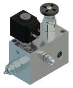
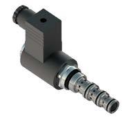
300 ELETTROVALVOLE SOLENOID VALVES
VALVOLE DI BILANCIAMENTO E BLOCCO A SEMPLICE EFFETTO IN LINEA SINGLE COUNTERBALANCE VALVES WITH IN LINE BODY. Valvole - Valves 01/B
 VALVOLE DI BILANCIAMENTO E BLOCCO A SEMPLICE EFFETTO IN LINEA SINGLE COUNTERBALANCE VALVES WITH IN LINE BODY Valvole - Valves 01/B Con il fine di migliorare costantemente la qualità dei nostri prodotti,
VALVOLE DI BILANCIAMENTO E BLOCCO A DOPPIO EFFETTO IN LINEA DOUBLE CONTERBALANCE VALVES WITH IN LINE BODY. Valvole - Valves 01/C
 VALVOLE DI BILANCIAMENTO E BLOCCO A DOPPIO EFFETTO IN LINEA DOUBLE CONTERBALANCE VALVES WITH IN LINE BODY Valvole - Valves 01/C DATI TECNICI TECHNICAL DATA Hydraulic valves and integrated components FLUIDO
SV10-42-C PERDITE DI CARICO SV C. Pressione - Dp [bar] DESCRIZIONE DESCRIPTION FUNZIONAMENTO OPERATION
![SV10-42-C PERDITE DI CARICO SV C. Pressione - Dp [bar] DESCRIZIONE DESCRIPTION FUNZIONAMENTO OPERATION](/thumbs/104/162537525.jpg "SV10-42-C PERDITE DI CARICO SV C. Pressione - Dp [bar] DESCRIZIONE DESCRIPTION FUNZIONAMENTO OPERATION") SV10-42-C Elettrovalvola a spool 7/8-14 UNF ad azione diretta 4 vie 2 posizioni (centro a Y ) 7/8-14 UNF solenoid spool valve, direct-acting, 4 way 2 positions ( motor center) DESCRIZIONE Elettrovalvola
SV10-42-C Elettrovalvola a spool 7/8-14 UNF ad azione diretta 4 vie 2 posizioni (centro a Y ) 7/8-14 UNF solenoid spool valve, direct-acting, 4 way 2 positions ( motor center) DESCRIZIONE Elettrovalvola
SV10-43-A PERDITE DI CARICO SV A. Pressione - Dp [bar] Portata Q [l/min] DESCRIZIONE DESCRIPTION FUNZIONAMENTO OPERATION
![SV10-43-A PERDITE DI CARICO SV A. Pressione - Dp [bar] Portata Q [l/min] DESCRIZIONE DESCRIPTION FUNZIONAMENTO OPERATION](/thumbs/98/136698555.jpg "SV10-43-A PERDITE DI CARICO SV A. Pressione - Dp [bar] Portata Q [l/min] DESCRIZIONE DESCRIPTION FUNZIONAMENTO OPERATION") SV10-43-A Elettrovalvola a spool 7/8-14 UNF ad azione diretta 4 vie 3 posizioni (centro chiuso) 7/8-14 UNF solenoid spool valve, direct-acting, 4 way 3 positions (closed center) DESCRIZIONE Elettrovalvola
SV10-43-A Elettrovalvola a spool 7/8-14 UNF ad azione diretta 4 vie 3 posizioni (centro chiuso) 7/8-14 UNF solenoid spool valve, direct-acting, 4 way 3 positions (closed center) DESCRIZIONE Elettrovalvola
VE N-100GAS-...
 V-...-150-114N-100GAS-... LTTROVALVOLA A CARTUCCIA A 2 VI PILOTATA SOLNOID PILOT OPRATD VALV, POPPT 2-WAY CARTRIDG STYL CARATTRISTICH Luce nominale Portata min/max Pressione max. Voltaggio minimo Temperatura
VALVOLE DI BILANCIAMENTO E BLOCCO A CARTUCCIA CON O SENZA COLLETTORE CARTRIDGE COUNTERBALANCE VALVES WITH OR WITHOUT BODY. Valvole - Valves 01/A
 VALVOLE DI BILANCIAMENTO E BLOCCO A CARTUCCIA CON O SENZA COLLETTORE CARTRIDGE COUNTERBALANCE VALVES WITH OR WITHOUT BODY Valvole - Valves 01/A Con il fine di migliorare costantemente la qualità dei nostri
VALVOLE DI MASSIMA PRESSIONE A CARTUCCIA CON COLLETTORE CARTRIDGE RELIEF VALVES WITH BODY
 VALVOLE DI MASSIMA PRESSIONE A CARTUCCIA CON COLLETTORE CARTRIDGE RELIEF VALVES WITH BODY Valvole - Valves 02/B Con il fine di migliorare costantemente la qualità dei nostri prodotti, ci riserviamo il
Sez./Section R Valvole per escavatori idraulici Hydraulic excavator Valves
 Sez./Section R Valvole per escavatori idraulici Hydraulic excavator Valves Valvole overcenter per escavatori Sono valvole overcenter specifiche per il controllo della discesa e sospensione dei bracci degli
Sez./Section D Valvole di ritegno unidirezionale Check Valves
 Sez./Section D Valvole di ritegno unidirezionale Check Valves Valvole di ritegno unidirezionali Queste valvole consentono il flusso libero in una direzione e lo impediscono nella direzione opposta. Sono
VALVOLE DI BILANCIAMENTO E BLOCCO FLANGIATE MOTORE COUNTERBALANCE MOTOR FLANGEABLE VALVES. Valvole - Valves 01/E
 VALVOLE DI BILANCIAMENTO E BLOCCO FLANGIATE MOTORE COUNTERBALANCE MOTOR FLANGEABLE VALVES Valvole - Valves 01/E Con il fine di migliorare costantemente la qualità dei nostri prodotti, ci riserviamo il
LUEN 01C_0 18/04/12 12.18 Pagina 1 VALVOLE DI BILANCIAMENTO E BLOCCO A DOPPIO EFFETTO IN LINEA DOUBLE CONTERBALANCE VALVES WITH IN LINE BODY
 LUEN 01C_0 18/04/12 12.18 Pagina 1 VALVOLE DI BILANCIAMENTO E BLOCCO A DOPPIO EFFETTO IN LINEA DOUBLE CONTERBALANCE VALVES WITH IN LINE BODY Valvole - Valves 01/C LUEN 01C_0 18/04/12 12.18 Pagina 2 Con
ANTIRRETORNO PILOTADO SIMPLE
 PILOTADO SIMPLE CARATTERISTICHE Luce nominale min/max Portata min/max Pressione di lavoro max. Temperatura ambiente Temperatura olio Filtraggio consigliato Vedi pag. 2 Vedi pag. 2 350 bar - 5075 PSI -30
VALVOLE DI BILANCIAMENTO E BLOCCO FLANGIATE COUNTERBALANCE VALVES WITH FLANGEABLE BODY
 VALVOLE DI BILANCIAMENTO E BLOCCO FLANGIATE COUNTERBALANCE VALVES WITH FLANGEABLE BODY Valvole - Valves 01/D Con il fine di migliorare costantemente la qualità dei nostri prodotti, ci riserviamo il diritto
VALVOLE DI BLOCCO A CARTUCCIA CARTRIDGE CHECK VALVES. Valvole - Valves 03/A
 VALVOLE DI BLOCCO A CARTUCCIA CARTRIDGE CHECK VALVES Valvole - Valves 03/A Con il fine di migliorare costantemente la qualità dei nostri prodotti, ci riserviamo il diritto di modificarne in qualsiasi momento
3/2 kleppen cartridges
 3/ kleppen cartridges www.findynamica.nl tel. +31 (0) 55 519919 sales@findynamica.nl FP-3-CD-S08-31-P- U 00/1 Rev.00-014/01 NEW 014 3 1 SPECIFICHE TECNICHE Materiali: cartuccia in acciaio zincato. Componenti
VALVOLE REGOLATRICI DI PORTATA FLOW CONTROL VALVES
 Con il fine di migliorare costantemente la qualità dei nostri prodotti, ci riserviamo il diritto di modificarne in qualsiasi momento le caratteristiche senza preavviso. È responsabilità della spettabile
VALVOLE REGOLATRICI DI PORTATA A CARTUCCIA CARTRIDGE FLOW CONTROL VALVES. Valvole - Valves 04/A
 VALVOLE REGOLATRICI DI PORTATA A CARTUCCIA CARTRIDGE FLOW CONTROL VALVES Valvole - Valves 04/A Con il fine di migliorare costantemente la qualità dei nostri prodotti, ci riserviamo il diritto di modificarne
VOC45/1 BI.CH VALVOLA OVERCENTER SINGOLA IN LINEA OVERCENTER VALVE SINGLE IN LINE COMANDO PILOTATO / PILOT OPERATED C1 C2 18
 VOC45/1 BI.CH DOPPIO EFFETTO / DOUBLE EFFECT Caratteristiche / Performances 71.5 2.5 CH. 17 CH. 27 C1 18 39.5 52.5 54 46 1 5 8.5 N 2 Fori PORTATA Flow Rate (Q max.) PRESSIONE Pressure (P max.) Corpo Body
VALVOLE DI BLOCCO CON COLLETTORE CHECK VALVES WITH BODY. Valvole - Valves 03/B
 VALVOLE DI BLOCCO CON COLLETTORE CHECK VALVES WITH BODY Valvole - Valves 03/B Con il fine di migliorare costantemente la qualità dei nostri prodotti, ci riserviamo il diritto di modificarne in qualsiasi
DATI TECNICI TECHNICAL DATA
 VALVOLE DI BILANCIAMENTO E CONTROLLO MOVIMENTO A SEMPLICE EFFETTO CON FUNZIONE RIGENERATIVA SINGLE COUNTERBALANCE VALVES WITH REGENERATIVE FUNCTION Valvole - Valves 07 Con il fine di migliorare costantemente
VALVOLE DI MASSIMA PRESSIONE A CARTUCCIA CARTRIDGE RELIEF VALVES. Valvole - Valves 02/A
 VALVOLE DI MASSIMA PRESSIONE A CARTUCCIA CARTRIDGE RELIEF VALVES Valvole - Valves 02/A Con il fine di migliorare costantemente la qualità dei nostri prodotti, ci riserviamo il diritto di modificarne in
Dual Cross Relief Valves
 16/03/1 TECH DATA SHEET 1034 Dual Cross Relief Valves TIPO / TYPE VAU SCHEMA IDRAULICO HYDRAULIC DIAGRAM IMPIEGO: Costituite da due valvole di massima pressione con scarico incrociato, sono utilizzate
Gestuurde terugslagkleppen leidingmontage, dubbele uitvoeringen
 Gestuurde terugslagkleppen leidingmontage, dubbele uitvoeringen www.findynamica.nl tel. +31 (0) 255 519919 sales@findynamica.nl FPD----/FPD---1R-- F 010/1 SPECIFICHE TECNICHE Materiali: corpo in acciaio,
Blocchi CETOP CETOP Manifold blocks. Blocchi - Manifold blocks 03
 Blocchi CETOP CETOP Manifold blocks Blocchi - Manifold blocks 03 Con il fine di migliorare costantemente la qualità dei nostri prodotti, ci riserviamo il diritto di modificarne in qualsiasi momento le
ELETTROVALVOLE SOLENOID VALVES. Valvole - Valves 05
 ELETTROVALVOLE SOLENOID VALVES Valvole - Valves 05 Con il fine di migliorare costantemente la qualità dei nostri prodotti, ci riserviamo il diritto di modificarne in qualsiasi momento le caratteristiche
Lanterne monoblocco Alta Gamma High size, one-piece bellhousings. Componenti - Components 04
 Lanterne monoblocco Alta Gamma High size, one-piece bellhousings Componenti - Components 04 Con il fine di migliorare costantemente la qualità dei nostri prodotti, ci riserviamo il diritto di modificarne
BOBINA PER SERVIZIO INTERMITTENTE ED 50% INTERMITTENT DUTY COIL ED 50% Hydraulic valves and integrated components CARATTERISTICHE
 E30 18W BOBINA PER SERVIZIO INTERMITTENTE E 50% INTERMITTENT UTY OIL E 50% 0.125 g 28VA 18W Power at the starting is 30 012 + R 1 2 29/30 17/18 19/20 E30 18W 30 onnection IN (Hirsch.) ostal avi - Leads
Oil-tanks and accessories for hydraulic power units
 Via M.L. King, 6-41122 MODENA (ITALY) Tel: +39 059 415 711 Fax: +39 059 415 729 / 059 415 730 INTERNET: http://www.hansatmp.it E-MAIL: hansatmp@hansatmp.it HYDRAULIC COMPONENTS HYDROSTATIC TRANSMISSIONS
VALVOLE DI MASSIMA PRESSIONE FLANGIATE MOTORE RELIEF VALVES WITH FLANGEABLE BODY
 VALVOLE DI MASSIMA PRESSIONE FLANGIATE MOTORE RELIEF VALVES WITH FLANGEABLE BODY Valvole - Valves 02/C Con il fine di migliorare costantemente la qualità dei nostri prodotti, ci riserviamo il diritto di
VALVOLE DI MESSA SCARICO POMPA DOPPIA PUMP UNLOADING VALVES
 VALVOLE DI MESSA SCARICO POMPA DOPPIA PUMP UNLOADING VALVES Valvole - Valves 02/E Con il fine di migliorare costantemente la qualità dei nostri prodotti, ci riserviamo il diritto di modificarne in qualsiasi
TD3.5 (dual displacement / cilindrata doppia) TV3.5 (variable displacement / cilindrata variabile)
 TV3.5 (variable displacement / cilindrata variabile)") TD3.5 (dual displacement / cilindrata doppia) TV3.5 (variable displacement / cilindrata variabile) Equivalent displacement Cilindrata equivalente Bore Alesaggio 600 150 (4) 800 200 (4) 1000 250 (4) 1200
TD3.5 (dual displacement / cilindrata doppia) TV3.5 (variable displacement / cilindrata variabile) Equivalent displacement Cilindrata equivalente Bore Alesaggio 600 150 (4) 800 200 (4) 1000 250 (4) 1200
TD3.5 (dual displacement / cilindrata doppia) TV3.5 (variable displacement / cilindrata variabile)
 TV3.5 (variable displacement / cilindrata variabile)") TD3.5 (dual displacement / cilindrata doppia) TV3.5 (variable displacement / cilindrata variabile) 600 150 (4) 800 200 (4) 1000 250 (4) 1100 280 (4) 1200 300 (4) Equivalent displacement Cilindrata equivalente
TD3.5 (dual displacement / cilindrata doppia) TV3.5 (variable displacement / cilindrata variabile) 600 150 (4) 800 200 (4) 1000 250 (4) 1100 280 (4) 1200 300 (4) Equivalent displacement Cilindrata equivalente
SERIE SP SERIES. Supporti pompa Pump supports
 SERIE SP SERIES Supporti pompa Accessori - Accessories 01 Con il fine di migliorare costantemente la qualità dei nostri prodotti, ci riserviamo il diritto di modificarne in qualsiasi momento le caratteristiche
GRUPPI INTEGRATI INTEGRATED BLOCKS. Valvole - Valves 06
 GRUPPI INTEGRATI INTEGRATED BLOCKS Valvole - Valves 06 Con il fine di migliorare costantemente la qualità dei nostri prodotti, ci riserviamo il diritto di modificarne in qualsiasi momento le caratteristiche
VALVOLE AD OTTURATORE COMANDO PNEUMATICO
 VALVOLE AD OTTURATORE COMANDO PNEUMATICO Attuatore con Pistone Pneumatico Corpo di Acciaio Inox A316, e Ottone Valvole Coassiali a Spola Comando Pneumatico ed Elettrico Corpo di Acciaio Inox A304 - A316
TD3.5 (dual displacement / cilindrata doppia) TV3.5 (variable displacement / cilindrata variabile)
 TV3.5 (variable displacement / cilindrata variabile)") TD3.5 (dual displacement / cilindrata doppia) TV3.5 (variable displacement / cilindrata variabile) Equivalent displacement Cilindrata equivalente Bore Alesaggio 600 150 (4) 800 200 (4) 1000 250 (4) 1200
TD3.5 (dual displacement / cilindrata doppia) TV3.5 (variable displacement / cilindrata variabile) Equivalent displacement Cilindrata equivalente Bore Alesaggio 600 150 (4) 800 200 (4) 1000 250 (4) 1200
SERIE SF-SP-SFM-SPM SERIES. Filtri in aspirazione immersi Suction strainers. serie spaccalegna / for log splitters
 SERIE SF-SP-SFM-SPM SERIES Filtri in aspirazione immersi Suction strainers Filtri - Filters 11 serie spaccalegna / for log splitters Con il fine di migliorare costantemente la qualità dei nostri prodotti,
VALVOLE REGOLATRICI DI PORTATA CON COLLETTORE FLOW CONTROL VALVES WITH BODY
 VALVOLE REGOLATRICI DI PORTATA CON COLLETTORE FLOW CONTROL VALVES WITH BODY Valvole - Valves 04/B Con il fine di migliorare costantemente la qualità dei nostri prodotti, ci riserviamo il diritto di modificarne
valvole Namur Namur valves
 valvole Namur La funzione della valvola può essere variata in qualsiasi momento, secondo lo schema qui riportato, cambiando di posto la guarnizione collocata sotto a uno dei due tappi avvitati nel corpo.
Cartridge volgorde kleppen
 Cartridge volgorde kleppen www.findynamica.nl tel. +31 (0) 255 519919 sales@findynamica.nl B 090/1 SPECIFICHE TECNICHE Materiali: cartuccia in acciaio zincato, parti interne in acciaio trattato termicamente.
valvole Namur Namur valves
 La funzione della valvola può essere variata in qualsiasi momento, secondo lo schema qui riportato, cambiando di posto la guarnizione collocata sotto a uno dei due tappi avvitati nel corpo. The function
FLOW REGULATORS USER S MANUAL MANUALE D USO. SITECNA SRL Via G. Di Vittorio Peschiera Borromeo Milan Italy
 R FLOW REGULATORS USER S MANUAL MANUALE D USO Max 12 bar SEALS FL FK LT NB RFU04NSS II2GD c IICT6X SITECNA SRL Via G. Di Vittorio 22 20068 Peschiera Borromeo Milan Italy USER'S MANUAL MANUALE D USO CONTENTS
Raccordi per pompe ad ingranaggi Couplings for gear pumps. Raccordi - Couplings 02
 Raccordi per pompe ad ingranaggi s for gear pumps Raccordi - s 02 Con il fine di migliorare costantemente la qualità dei nostri prodotti, ci riserviamo il diritto di modificarne in qualsiasi momento le
Attuatore pneumatico semplice effetto SR in alluminio Aluminium spring return pneumatic actuator SR type
 Attuatore pneumatico semplice effetto SR in alluminio Aluminium spring return pneumatic actuator SR type DATI TECNICI Coppia da 15 Nm a 000 Nm. Flangia d attacco: F03 - F0 - F05 - F07 - F10 - F12 - F1
valvole Namur Namur valves
 La funzione della valvola può essere variata in qualsiasi momento, secondo lo schema qui riportato, cambiando di posto la guarnizione collocata sotto a uno dei due tappi avvitati nel corpo. The function
LC1AZ - LC1DZ. Elettrovalvole dirette controllo direzione Solenoid operated directional valves
 LCAZ - LCDZ Elettrovalvole dirette controllo direzione Solenoid operated directional valves A B a P T b CARATTERISTICHE TECNICHE Grandezza: NG ISO - CETOP RP H- (CETOP ) LCAZ - CORRENTE ALTERNATA: Portata
VALVOLE ANTIURTO DUAL CROSS RELIEF VALVES
 VALVOLE ANTIURTO DUAL CROSS RELIEF VALVES OLEODINAMICA MARCHESINI.1 - VALVOLE ANTIURTO.1 - DUAL CROSS RELIEF VALVES tipo/ type VAU SCHEMA IDRAULICO HYDRAULIC DIAGRAM IMPIEGO: Costituite da due valvole
VALVOLE ANTIURTO DUAL CROSS RELIEF VALVES
 VALVOLE ANTIURTO DUAL CROSS RELIEF VALVES OLEODINAMICA MARCHESINI.1 - VALVOLE ANTIURTO.1 - DUAL CROSS RELIEF VALVES tipo/type VAU SCHEMA IDRAULICO HYDRAULIC DIAGRAM IMPIEGO: Costituite da due valvole di
CAP 4 Elettrovalvole e valvole pneumatiche Solenoid and pneumatic valves
 CAP 4 Elettrovalvole e valvole pneumatiche Solenoid and pneumatic valves 4.0 mm Manifold and single elettrovalvola /-/vie G/ solenoid valve /-/ways G/ comando elettropneumatico diretto riposizionamento
Filtri per spaccalegna Filters for log splitters
 Filtri in aspirazione immersi Suction strainers serie SF - SP - SFM - SPM series Filtri per spaccalegna Filters for log splitters Pag.3 Descrizione Description I filtri della serie SF-SP-SFM-SPM sono stati
Codice ordinazione Ordering code. Molla (Spring) 10/90 bar (145/1305 PSI) max. 20/210 bar (290/3045 PSI) max. Performances
 10/90 bar (145/1305 PSI) max. 20/210 bar (290/3045 PSI) max. Performances") asi singole cetop3 in alluminio - attacchi laterali S3 luminium cetop3 single manifolds - lateral ports odice ordinazione Ordering code 3 S3 asi singole cetop3 in alluminio - attacchi laterali (luminium
asi singole cetop3 in alluminio - attacchi laterali S3 luminium cetop3 single manifolds - lateral ports odice ordinazione Ordering code 3 S3 asi singole cetop3 in alluminio - attacchi laterali (luminium
R Stainless steel AISI 316L high pressure regulator, suitable for compressed air, gas and liquid
 Strada dei Boschi, 40 20852 Villasanta (MB) Italia tel. +39 039 302035 info@idinsertdeal.com www.idinsertdeal.com R33000 Stainless steel AISI 316L high pressure regulator, suitable for compressed air,
Voorspankleppen leidingmontage
 Voorspankleppen leidingmontage www.findynamica.nl tel. +31 (0) 255 519919 sales@findynamica.nl FPSQ-D-15-CB--1/4--- B 015/1 Valvola di sequenza ad azione diretta, montaggio in linea Direct acting sequence
R2034. Brass two stage high pressure regulator, suitable for laboratory use
 Strada dei Boschi, 40 20852 Villasanta (MB) Italia tel. +39 039 302035 info@idinsertdeal.com www.idinsertdeal.com R2034 Brass two stage high pressure regulator, suitable for laboratory use FEATURES High
valvole Namur Namur valves
 La funzione della valvola può essere variata in qualsiasi momento, secondo lo schema qui riportato, cambiando di posto la guarnizione collocata sotto a uno dei due tappi avvitati nel corpo. The function
Afschakelkleppen Fluid Press
 Afschakelkleppen Fluid Press www.findynamica.nl tel. +31 (0) 255 519919 sales@findynamica.nl FPMS-P--- V 150/1 Valvola di messa a scarico, idropilotata Pilot operated unloading valve SPECIFICHE TECNICHE
valvole unidirezionali one-way valves
 La FOR rafforza la propria gamma prodotti con l introduzione delle. Tali valvole permettono il libero passaggio in un solo senso (quello indicato dalla freccia) e lo impediscono nel senso contrario. Azionate
SERIE SF - SP SERIES. Filtri in aspirazione immersi Suction strainers. serie spaccalegna / for log splitters
 SERIE SF - SP SERIES Filtri in aspirazione immersi Suction strainers Filtri - Filters 11 serie spaccalegna / for log splitters Con il fine di migliorare costantemente la qualità dei nostri prodotti, ci
VALVOLE AUSILIARIE AUXILIARIES VALVES
 VALVOLE AUSILIARIE AUXILIARIES VALVES Valvole di blo cco pilotate Pilot -operat ed check v alv es Valvole re golatrici di flus s o Flow cont rol v alv es Valvole limita trici di pre s s ione Pressure relief
SERIE LR25 SERIES. Lanterne ventilate Cooled bellhousings
 SERIE LR25 SERIES Lanterne ventilate Cooled bellhousings Componenti - Components 03 Con il fine di migliorare costantemente la qualità dei nostri prodotti, ci riserviamo il diritto di modificarne in qualsiasi
Blocchi CETOP CETOP Manifold blocks
 Blocchi CETP CETP Manifold blocks Blocchi - Manifold blocks 03 Con il fine di migliorare costantemente la qualità dei nostri prodotti, ci riserviamo il diritto di modificarne in qualsiasi momento le caratteristiche
VOC45 SQ.AB.VS.VU VALVOLA DI SEQUENZA IN LINEA SEQUENCE VALVE IN LINE PER ESCLUSIONE ALTA-BASSA PRESSIONE FOR HIGH-LOW PRESSURE CUT-OFF T BP AP
 VOC45 SQ..VS.VU VLVOL DI SEQUENZ IN LINE SEQUENCE VLVE IN LINE PER ESCLUSIONE L-SS PRESSIONE FOR HIGH-LOW PRESSURE CU-OFF Caratteristiche / Performances 22 39 39 VOC45 65 55 95 P P 39 61 1 N 4 Filetti
AVP MD14 AVP MD12. Combined soft start/dump valve for compressed air FEATURES
 Strada dei Boschi, 40 20852 Villasanta (MB) Italia tel. +39 039 302035 info@idinsertdeal.com www.idinsertdeal.com AVP MD14 AVP MD12 Combined soft start/dump valve for compressed air FEATURES Combined soft
Attuatore pneumatico doppio effetto DA Double acting pneumatic actuator DA type
 Attuatore pneumatico doppio effetto DA Double acting pneumatic actuator DA type DATI TECNICI Coppia da 8 Nm. a 8000 Nm. Flangia d attacco: DIN/ISO 5211 DIN 3337 F03 - F04 - F05 - F07 - F10 - F12 - F14
Oliestroomdelers leidingmontage
 Oliestroomdelers leidingmontage www.findynamica.nl tel. +31 (0) 255 519919 sales@findynamica.nl FPFD--C(B)---- N 050/1 Divisore/riunificatore flusso Flow divider/combiner Rev.03-2010/10 SPECIFICHE TECNICHE
2 weg drukgecompenseerde oliestroomregelaars
 2 weg drukgecompenseerde oliestroomregelaars www.findynamica.nl tel. +31 (0) 255 519919 sales@findynamica.nl Tipo /Type Sez./Section Pag./Page FPCU-* M 010/1 Valvola regolatrice di flusso unidirezionale
VALVOLE A SFERA: IDEAL BALL VALVES : IDEAL CATALOGO TECNICO TECHNICAL CATALOGUE
 VALVOLE A SFERA: IDEAL BALL VALVES : IDEAL CATALOGO TECNICO TECHNICAL CATALOGUE B E C Valvola a sfera IDEAL, passaggio totale IDEAL ball valve, full flow 090 VOCI DI CAPITOLATO - TECHNICAL FEATURES Attacchi
DISTRIBUTORS / DISTRIBUTORI
 DISTRIBUTORS / DISTRIBUTORI Speed Pressure Flow [rpm] [bar] [l/min]...... D20 D30 D3,, D4,, / D5,, D90 D250 HS LS LS LS HS HS HS cont. 900 300 300 1200 1600 700 500 max. 1300 500 500 2400 1200 1000 cont.
SERIE APM-110 BAR SERIES. Filtri in linea a media pressione In line filter medium pressure. Filtri - Filters 09
 SERIE APM-110 BAR SERIES Filtri in linea a media pressione In line filter medium pressure Filtri - Filters 09 Con il fine di migliorare costantemente la qualità dei nostri prodotti, ci riserviamo il diritto
VALVOLE PER MOTORI HT - HTC HT - HTC MOTORS VALVES. Informativa tecnica Technical information 15/11/01 n 011/01 pag. 1/5 orbital division VCD1 10 S-AF
 15/11/01 n 011/01 pag. 1/5 VALVOLE PER MOTORI HT - HTC Valvole flangiabili disponibili per motori HT - HTC: 1. Valvola singola controllo discesa 2. Valvola antiurto doppia incrociata 3. Valvola controllo
Valvole Sfera Ball Valves 5.1
 5 Valvole Sfera Ball Valves 5.1 ZVS Valvola ZVS Sfera Eccellente prodotto per impieghi dove si richieda un passaggio totale. La valvola Sfera ZVS-VVS di Bardiani Valvole è realizzata sia con comando pneumatico
Blocchi CETOP CETOP Manifold blocks
 Blocchi CETP CETP Manifold blocks Blocchi - Manifold blocks 03 Con il fine di migliorare costantemente la qualità dei nostri prodotti, ci riserviamo il diritto di modificarne in qualsiasi momento le caratteristiche
valvole ad azionamento elettropneumatico
 Valvole a spola 3/2-5/2-5/3 con attacchi filettati G/8 -G/4 3/2-5/2-5/3 spool valves with G/8 -G/4 threaded ports Montaggio in linea, su collettori multipli o su basi manifold Installation in-line, on
VALVOLE OLEODINAMICHE HYDRAULIC VALVES
 VALVOLE OLEODINAMICHE HYDRAULIC VALVES CTVLREV2IE CATALOGO TECNICO TECHNICAL CATALOGUE CARATTERISTICHE GENERALI MAIN FEATURES Materiale Tutti i materiali utilizzati per i vari prodotti, sono di buona qualità;
PIL V2 > C C2 > V V2 > C2 01 C2 > V2 01. dimensioni e pesi - external dimensions and weights
 scheda - card prodotto - product schema - schema WBS M/ PIL semplice effetto ollegare la bocca all alimentazione, la bocca alla bocca dell attuatore da controllare e la bocca Pil. alla pressione di pilotaggio.
CATALOGO TECNICO LUGLIO 2004
 POMPE A MANO HAND PUMPS CATALOGO TECNICO LUGLIO 2004 TECHNICAL CATALOGUE JULY 2004 G.L. HYDRAULIC S.R.L. VIA F. LAMBORGHINI, 36 40019 SANT AGATA BOLOGNESE ( BO ) ITALY TEL : +39 (0)516828230 FAX : +39
MD10V 14/18 MANUALE DELL OPERATORE OPERATOR MANUAL
 Cod. 05-0062-A03 MD10V 14/18 MANUALE DELL OPERATORE OPERATOR MANUAL REGOLATORE MANUALE SENZA AZZERATORE MANUAL WITHOUT ZEROING CONTROL (HLW) A, B D1, D2 S P Va V1, V2 Sl Utilizzi Pressure Ports Drenaggi
ALTA PRESSIONE A 2 E TRE VIE CATALOGO HIGH PRESSURE TWO-THREE WAYS BALL-VALVES ENTER
 CATALOGO 01-001-4 VALVOLE A SFEA ALTA PSIONE A 2 E TE VIE HIGH PSUE TWO-THEE WAYS BALL-VALV ENTE Le valvole a sfera CIOCCA "CH", grazie alla tecnologia, consentono un impiego anche in condizioni di lavoro
Cross over kleppen zonder nazuig
 Cross over kleppen zonder nazuig www.findynamica.nl tel. +31 (0) 255 519919 sales@findynamica.nl FPM-D-40-IL--3/8--- A 280/1 SPECIFICHE TECNICHE Materiali: cartuccie in acciaio zincato, parti interne in
VALVOLE A FARFALLA IN PVC-U SERIE CLASSIC
 PVC-U Butterfly Valves - Classic Series VVALVOLE A FARFALLA PVC-U - Serie Classic Dimensioni D63 - D (DN6 - DN) - Standard Pressione di lavoro ISO/DIN, British Standard, ANSI/ASTM, JIS @ ºC (73ºF) EN -
valvole 16 mm ad azionamento pneumatico
 valvole 6 mm ad azionamento pneumatico - 6 mm Valvole a spola 5/ con attacchi filettati M5 o G/8 (scarichi M5) 5/ spool valves with M5 or G/8 threaded ports (M5 exhaust ports) Spessore della valvola: 6
Valvole taglia 22mm. Valves size 22mm. Materiali impiegati. 1 OPERATORE: Ottone, Acciaio INOX 2 CORPO OPERATORE: PA. 3 CORPO VALVOLA: Alluminio
 Valvole taglia 22mm Valves size 22mm Caratteristiche Genarali Funzionamento: a spola Taglia valvola: 22mm Connessione: 1/4 Materiale corpo: alluminio Uso Singolo: Si Uso sottobase: Si Funzioni disponibili:
MB 1010 MOTORIDUTTORI ORBITALI ORBITAL GEARED MOTORS
 MB 1010 MOTORIDUTTORI ORBITALI ORBITAL GEARED MOTORS 41/56 CARATTERISTICHE DEL PRODOTTO PRODUCT FEATURES I motoriduttori della serie MB 1010 sono composti di riduttore epicicloidale monostadio ad albero
MF Motore a pistoni assiali a cilindrata fissa Fixed-displacement axial piston motors
 Motore a pistoni assiali a cilindrata fissa Fixed-displacement axial piston motors CARATTERISTICHE TECNICHE TECHNICAL FEATURES I motori a pistoni assiali a cilindrata fissa sono a piatto inclinato e possono
Freni idraulici multidisco serie F Hydraulic Multidisc Brakes F Series
 HYDRAULIC COMPONENTS HYDROSTATIC TRANSMISSIONS GEARBOXES - ACCESSORIES Via M.L. King, 6-41122 MODENA (ITALY) Tel: +39 059 415 711 Fax: +39 059 415 729 / 059 415 730 INTERNET: http://www.hansatmp.it E-MAIL:
MAGNET LINK SURFACE MOUNTED
 MAGNET LINK SURFACE MOUNTED unonovesette LIGHTING INSTRUMENTS MAGNET LINK SURFACE MOUNTED is a low-voltage magnetic track in Class III SELV, Designed to power constant-voltage LED luminaires. The 4 conductors
oscillatore Modalità di funzionamento Valve operation oscillating valve
 oscillatore oscillating valve Modalità di funzionamento Valve operation È una valvola di potenza che consente a un cilindro a doppio effetto o a un analogo impianto pneumatico di effettuare la fase di
SERIE HPB BAR SERIES. Filtri alta pressione High pressure filters
 SERIE HPB - 31 BAR SERIES Filtri alta pressione High pressure filters Filtri - Filters 10 Con il fine di migliorare costantemente la qualità dei nostri prodotti, ci riserviamo il diritto di modificarne
Contenitori in vetroresina per cartucce filtranti Fiberglass housings for filter cartridges
 Contenitori in vetroresina per cartucce filtranti Fiberglass housings for filter cartridges I contenitori multicartuccia modello FIB sono realizzati completamente in vetroresina. Filtro FIB Vantaggi I
MV Motore a pistoni assiali a cilindrata variabile Variable displacement axial piston motors
 Motore a pistoni assiali a cilindrata variabile Variable displacement axial piston motors CARATTERISTICHE TECNICHE TECHNICAL FEATURES I motori variabili a pistoni assiali sono stati concepiti per operare
R123 R123/34 brass. Brass pressure regulator, for compressed air, gas and liquid
 Strada dei Boschi, 40 20852 Villasanta (MB) Italia tel. +39 039 302035 info@idinsertdeal.com www.idinsertdeal.com R123 R123/34 brass Brass pressure regulator, for compressed air, gas and liquid FEATURES
DISTRIBUTORI ROTANTI ELETTRICI E ELETTRO-IDRAULICI ELECTRO-HYDRAULIC ROTARY COUPLING
 Via M.L. King, - 22 MODENA (ITALY) Tel: +39 059 5 7 Fax: +39 059 5 729 / 059 5 730 INTERNET: http://www.hansatmp.it E-MAIL: hansatmp@hansatmp.it HYDRAULIC COMPONENTS HYDROSTATIC TRANSMISSIONS GEARBOXES
Materiali impiegati. 1 OPERATORE: Ottone, Acciaio INOX 2 CORPO OPERATORE: POM. 3 CORPO VALVOLA: Alluminio. 6 MOLLA: Acciaio INOX
 127 1/8-1/4 Elettrovalvole e valvole pneumatiche Solenoid and pneumatic valves Caratteristiche Genarali Funzionamento: a spola Taglia valvola: 22mm Connessione: 1/8-1/4 Materiale corpo: alluminio Uso Singolo:
RFU 1/8.2 RFUM 1/8 RFU 1/8.3 G1/8 G1/8. 2 mm 4.2 mm 120 Nl/min 450 Nl/min. 3.2 mm 4.2 mm 210 Nl/min 450 Nl/min bar MPa RFB 1/8 G1/8
 regolatori di flusso flow regulators Regolatori unidirezionali e bidirezionali Uni-directional and bi-directional flow regulators Attacchi filettati da M5 a Threaded ports from M5 to Montaggio in linea
valvole oleodinamiche HYDRaUlIC valves
 valvole OLEODINAMICHE HYDRAULIC VALVES CTVLIE catalogo tecnico technical catalogue CARATTERISTICHE GENERALI MAIN FEATURES Materiale Tutti i materiali utilizzati per i vari prodotti, sono di buona qualità;