XC77 XAC77. Manuale d uso. Elenco sezioni. 1 - Norme di sicurezza. XC77 XAC77 - Encoder ATEX
|
|
|
- Cosima Arcuri
- 7 anni fa
- Visualizzazioni
Transcript

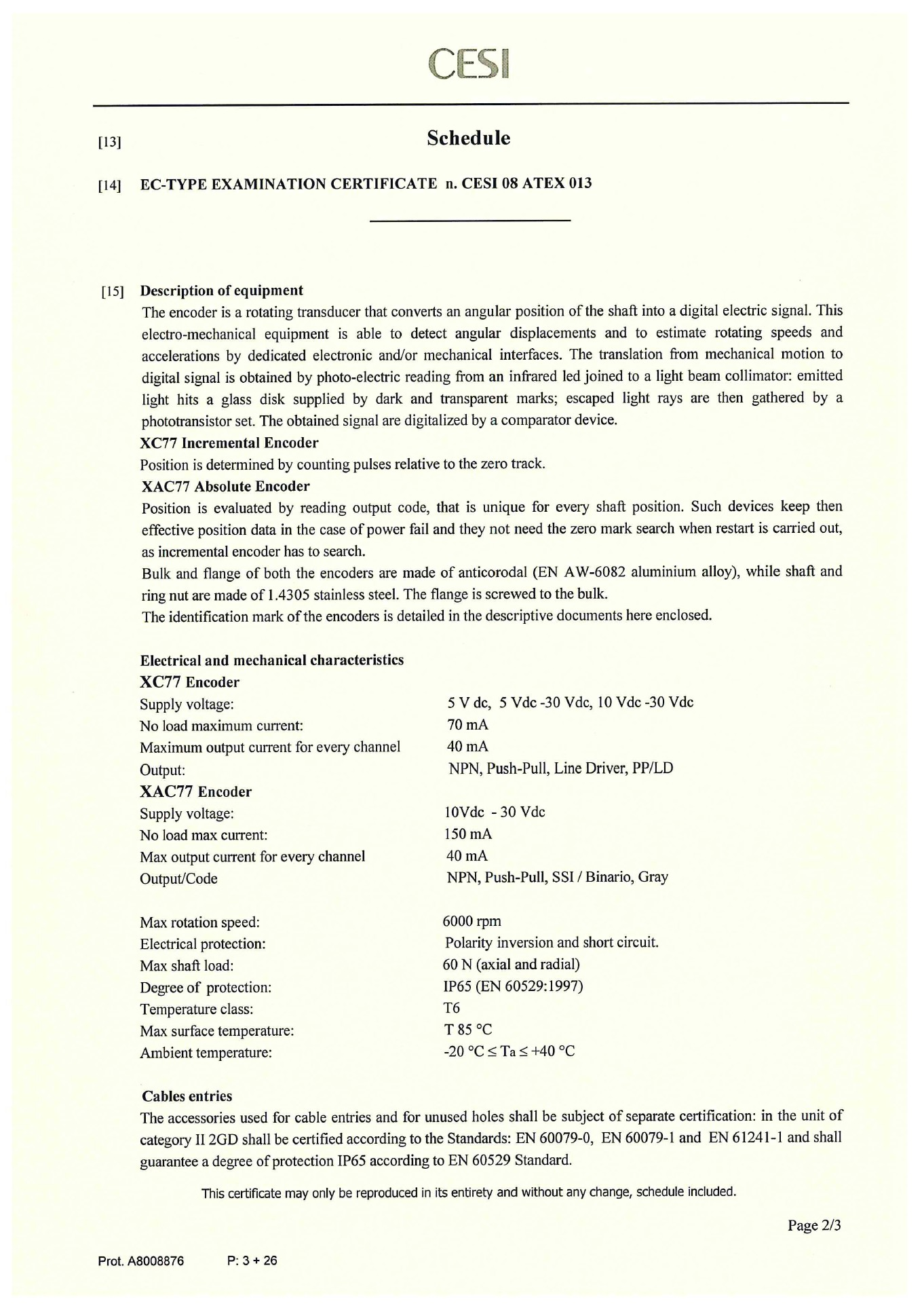
1 2001 Manuale d uso XC77 XAC77 II2 GD, Ex d IIC T6 Gb, Ex tb IIIC T85 C Db, IP65 II2 GD, Ex d IIB T6 Gb, Ex tb IIIC T85 C Db, IP65 Elenco sezioni 1 - Norme di sicurezza 2 - Identificazione 3 - Certificato ATEX 4 - Dichiarazione di Conformità UE 5 Istruzioni di sicurezza 6 - Connessioni elettriche 7 - Caratteristiche meccaniche 1 - Norme di sicurezza Sicurezza Attenersi scrupolosamente alle informazioni in questo manuale relative ai prodotti ATEX; durante l installazione e l utilizzo del dispositivo osservare le norme di prevenzione e sicurezza sul lavoro previste nel proprio paese; l installazione e le operazioni di manutenzione devono essere eseguite da personale qualificato, in assenza di tensione e parti meccaniche in movimento; utilizzare il dispositivo esclusivamente per la funzione per cui è stato costruito: ogni altro utilizzo potrebbe risultare pericoloso per l'utilizzatore; alte correnti, tensioni e parti in movimento possono causare lesioni serie o fatali; il mancato rispetto delle norme di sicurezza o delle avvertenze specificate in questo manuale è considerato una violazione delle norme di sicurezza standard previste dal costruttore o richieste dall'uso per cui lo strumento è destinato; Lika Electronic non si assume alcuna responsabilità per eventuali danni o lesioni derivanti dall'inosservanza delle norme di sicurezza da parte dell'utilizzatore. 1
2 Avvertenze elettriche Effettuare le connessioni elettriche esclusivamente in assenza di tensione; rispettare le connessioni riportate nella sezione 6 - Connessioni elettriche ; i fili dei segnali d uscita non utilizzati devono essere isolati singolarmente; encoder assoluti: collegare gli ingressi Azzeramento e Direzione di conteggio a 0Vdc se non utilizzati; - per azzerare la posizione collegare Azzeramento a +Vdc per almeno 100 µs, poi scollegare +Vdc; normalmente deve avere tensione 0Vdc; effettuare l'azzeramento dopo l'impostazione di Direzione di conteggio; effettuare l'azzeramento con encoder fermo; - Direzione di conteggio: conteggio crescente con rotazione oraria (vista lato albero) = collegarlo a 0Vdc; conteggio crescente con rotazione antioraria = collegarlo a +Vdc; in riferimento alla normativa 2014/30/UE sulla compatibilità elettromagnetica rispettare le seguenti precauzioni: - prima di maneggiare e installare il dispositivo eliminare la presenza di carica elettrostatica dal proprio corpo e dagli utensili che andranno a contatto con il dispositivo; - alimentare il dispositivo con tensione stabilizzata e priva di disturbi, se necessario, installare appositi filtri EMC all ingresso dell alimentazione; - utilizzare sempre cavi schermati e possibilmente twistati ; - non usare cavi più lunghi del necessario; - evitare di far passare il cavo dei segnali del dispositivo vicino a cavi di potenza; - installare il dispositivo il più lontano possibile da possibili fonti di interferenza o schermarlo in maniera efficace; - per garantire un funzionamento corretto del dispositivo, evitare l'utilizzo di apparecchiature con forte carica magnetica in prossimità dell'unità; - collegare la calza del cavo e/o il corpo del dispositivo a un buon punto di terra; assicurarsi che il punto di terra sia privo di disturbi. Il collegamento a terra può essere effettuato sul lato dispositivo e/o sul lato utilizzatore; è compito dell utilizzatore valutare la soluzione migliore da adottare per minimizzare i disturbi. Avvertenze meccaniche Montare il dispositivo rispettando rigorosamente le istruzioni riportate nella sezione 7 Caratteristiche meccaniche ; effettuare il montaggio meccanico esclusivamente in assenza di parti meccaniche in movimento; non disassemblare il dispositivo; non eseguire lavorazioni meccaniche sul dispositivo; dispositivo elettronico delicato: maneggiare con cura; evitare urti o forti sollecitazioni sia all asse che al corpo del dispositivo; utilizzare il dispositivo in accordo con le caratteristiche ambientali previste dal costruttore, encoder con asse cavo: l'encoder può essere montato direttamente su un albero che rispetti le caratteristiche definite nel foglio d'ordine e fissato mediante il collare. 2 - Identificazione Il dispositivo è identificato mediante un codice di ordinazione e un numero di serie stampati sull'etichetta applicata al dispositivo stesso; i dati sono ripetuti anche nei documenti di trasporto che lo accompagnano. Citare sempre il codice di ordinazione e il numero di serie quando si contatta Lika Electronic per l'acquisto di un ricambio o nella necessità di assistenza tecnica. Per ogni informazione sulle caratteristiche tecniche del dispositivo fare riferimento al catalogo del prodotto. 2

3 3 - Certificato ATEX 3
4 4

5 5
6 6
7 7
8 8

9 9
10 4 - Dichiarazione di Conformità UE 10
11 5 Istruzioni di sicurezza 11
12 12
13 6 - Connessioni elettriche ATTENZIONE Effettuare le connessioni elettriche esclusivamente in assenza di tensione. ATTENZIONE La chiusura di contatto tra i segnali non utilizzati può provocare il danneggiamento irrimediabile del dispositivo. Collegare la calza del cavo e/o il corpo del dispositivo a un buon punto di terra; assicurarsi che il punto di terra sia privo di disturbi. Il collegamento a terra può essere effettuato sul lato dispositivo e/o sul lato utilizzatore; è compito dell utilizzatore valutare la soluzione migliore da adottare per minimizzare i disturbi. 6.1 Lunghezza minima del cavo Per soddisfare i requisiti di protezione gas secondo la marcatura ATEX II2 GD Ex d IIC T6 Gb, i dispositivi XC e XAC sono forniti con un cavo della lunghezza minima di 3 m. Il cavo non deve mai essere accorciato! Se questo avvenisse il livello di protezione gas sarebbe inferiore e conforme alla marcatura II2 GD Ex d IIB T6 Gb. 6.2 XC77- -ZCU Funzione A /A B /B 0 /0 +Vdc 0Vdc alimentazione Schermatura Cavo I8 8 poli Giallo Blu Verde Arancione Bianco Grigio Rosso Nero Calza 13
14 6.3 XAC77 con interfaccia SSI Funzione Clock IN + Clock IN Data OUT + Data OUT Azzeramento Direzione di conteggio +10Vdc +30Vdc 0Vdc alimentazione Schermatura Cavo A8 8 poli Bianco Marrone Verde Giallo Rosa Blu Rosso Nero Calza 14
15 6.4 XAC77 con uscita parallela (NPN o.c. / Push-Pull) Funzione Cavo A16 16 poli Cavo A19 19 poli Cavo A32 32 poli Marrone Marrone Marrone 1 LSB Rosso Rosso Rosso 2 Rosa Rosa Rosa 3 Giallo Giallo Giallo 4 Verde Verde Verde 5 Blu Blu Blu 6 Viola Viola Viola 7 Grigio Grigio Grigio 8 Bianco Bianco Bianco 9 Nero Nero Nero 10 Bianco/Verde Bianco/Verde Marrone/Rosso 11 Marrone/Verde Marrone/Verde Bianco/Rosso 12 Rosso/Blu Rosso/Blu 13 Grigio/Marrone Grigio/Rosa 14 Bianco/Grigio Bianco/Giallo 15 Marrone/Verde 16 Bianco/Verde 17 Giallo/Marrone 18 Bianco/Blu 19 Marrone/Blu 20 Bianco/Rosa 21 Bianco/Grigio 22 Rosa/Marrone 23 Grigio/Marrone 24 Marrone/Nero 25 Rosso/Blu Bianco/Rosa Grigio/Verde Azzeramento Grigio/Rosa Grigio/Rosa Giallo/Rosa Direzione di conteggio Bianco/Giallo Bianco/Giallo Verde/Blu +10Vdc +30Vdc Giallo/Marrone Giallo/Marrone Giallo/Blu 0Vdc alimentazione Calza Calza Calza Schermatura 15
16 6.5 XAC77 con interfaccia Profibus (XAC77xx/xxxxxPB-...) Gli encoder ATEX con interfaccia Profibus rispecchiano le caratteristiche di comunicazione degli encoder serie Hx58 FB, le eventuali differenze sono indicate in basso; i file GSD (HS58_Vx.gsd per monogiro e HM58_Vx.gsd per multigiro) e il manuale relativo all interfaccia Profibus sono disponibili all indirizzo > PRODOTTI > ENCODER ROTATIVI > ENCODER ASSOLUTI > PROFIBUS > Hx58 FB). Funzione +10Vdc +30Vdc Alimentazione 0Vdc Alimentazione Cavo Rosso Bianco Profibus B (bus input) Profibus A (bus input) Blu Bianco Profibus B (bus output) Profibus A (bus output) Verde Bianco +5Vdc out per RT1 0Vdc out per RT1 Giallo Bianco Profibus Shield Calza 1 I due fili sono provvisti di protezione in guaina termorestringente; assicurarsi che la protezione sia sempre presente se la terminazione RT non è installata (danneggiamenti irreversibili!). ATTENZIONE L indirizzo del nodo deve essere impostato via software dal Master utilizzando il servizio SAP55, per ogni informazione si veda la sezione Impostazione indirizzo nodo via BUS (servizio SAP55) a pagina 17. Come default Lika imposta l'indirizzo = 125; per modificare tale indirizzo è necessario installare un solo encoder per volta e quindi modificare l'id, altrimenti si crea conflitto tra i nodi. Con codice /AABT (vedi datasheet) l'indirizzo AA (eccetto AA = 7Eh) non è modificabile. Il baud rate è settato automaticamente dal Master. NON è consentito aprire l encoder! I LED di diagnostica non sono presenti su questo modello. Il cavo utilizzato non è certificato Profibus, ma prevede l'ingresso e l'uscita bus per evitare Stub sulla rete Profibus. Se il dispositivo è il primo o l'ultimo della rete si deve terminare il bus con un terminatore attivo certificato o implementando il seguente schema alle uscite. Con codice /AABT (vedi datasheet), se T = 1, la resistenza è installata, attiva e non disattivabile (non montare resistenze esterne!). Per evitare danni irreversibili all'encoder i fili non utilizzati devono essere tagliati a lunghezze diverse e isolati singolarmente. 16
17 6.5.1 Impostazione indirizzo nodo via BUS (servizio SAP55) ATTENZIONE Il servizio SAP55 può essere eseguito solamente utilizzando un DP Master Class 2 (DPM2). I Master di classe 1 (DPM1) non sono in grado di eseguire il servizio SAP55. Con codice /AABT (vedi datasheet) l'indirizzo AA (eccetto AA = 7Eh) non è modificabile. I dispositivi Lika della serie XAC77 prevedono l'impostazione dell'indirizzo del nodo via bus mediante il servizio SAP55. Il servizio Service Access Point SAP55 Set_Slave_Address permette la modifica dell'indirizzo di un dispositivo slave memorizzato nella memoria interna permanente. Il servizio SAP55 è previsto dalle specifiche Profibus per l'impostazione dell'indirizzo del nodo in alternativa agli switch hardware, nel caso in cui questi non siano previsti o non sia possibile utilizzarli. L'indirizzo di default memorizzato da Lika Electronic nella memoria interna è 125. Impostazione mediante STEP7 di Siemens Per modificare l'indirizzo salvato nella memoria interna, accedere alla finestra SIMATIC Manager ed eseguire il comando Assegna indirizzo PROFIBUS nel menu Sistema di destinazione\profibus. Si aprirà la finestra Assegna indirizzo PROFIBUS. Nella finestra Assegna indirizzo PROFIBUS impostare l indirizzo correntemente memorizzato nella memoria interna (impostazione di fabbrica = 125 ) nel menu a tendina Indirizzo PROFIBUS attuale e indicare il nuovo indirizzo da impostare nel sottostante combo box Nuovo indirizzo PROFIBUS (per esempio: 6 ); quindi premere Conferma e di seguito OK. 17
18 6.6 XAC77 con interfaccia CANopen (XAC77xx/xxxxxCB-...) Gli encoder ATEX con interfaccia CANopen rispecchiano le caratteristiche di comunicazione degli encoder serie Hx58 FB, le eventuali differenze sono indicate in basso; i file EDS (Lika_HSxCB_DS406_Vx.eds per monogiro e Lika_HMxCB_DS406_Vx.eds per multigiro) e il manuale relativo all interfaccia CANopen sono disponibili all indirizzo > PRODOTTI > ENCODER ROTATIVI > ENCODER ASSOLUTI > CAN > Hx58 FB). Funzione +10Vdc +30Vdc Alimentazione 0Vdc Alimentazione Cavo Rosso Bianco CAN L (bus input) CAN H (bus input) Blu Bianco CAN L (bus output) CAN H (bus output) Verde Bianco Non usato Non usato Giallo Bianco CAN Shield Calza ATTENZIONE L indirizzo del nodo e il baud rate devono essere impostati via software dal Master (si veda ai parametri 3000h e 3001h del Dizionario oggetti ). Come default Lika imposta l'indirizzo = 1 e il baud rate = 500 Kbit/s; per modificare l'indirizzo preimpostato è necessario installare un solo encoder per volta e quindi modificare l'id, altrimenti si crea conflitto tra i nodi. Con codice /AABT (vedi datasheet) l'indirizzo AA (eccetto AA = 00h) e il baud rate B (eccetto B = Z) non sono modificabili. NON è consentito aprire l encoder! I LED di diagnostica non sono presenti su questo modello. Il cavo utilizzato non è certificato CANbus, ma prevede l'ingresso e l'uscita bus per evitare Stub sulla rete CANbus. Se l encoder è il primo o l ultimo dispositivo della rete, la resistenza di terminazione deve essere montata esternamente al dispositivo (terminale di rete da 120 tra le uscite CAN High e CAN Low), come mostrato nel seguente schema. Con codice /AABT (vedi datasheet), se T = 1, la resistenza è installata, attiva e non disattivabile (non montare resistenze esterne!). Per evitare danni irreversibili all'encoder i fili non utilizzati devono essere tagliati a lunghezze diverse e isolati singolarmente. 18
19 6.7 XAC77 con interfaccia DeviceNet (XAC77xx/xxxxxFD-...) Gli encoder ATEX con interfaccia DeviceNet rispecchiano le caratteristiche di comunicazione degli encoder serie Hx58 FB, le eventuali differenze sono indicate in basso; i file EDS (Lika_HS58x_FDV_Vx.eds per monogiro e Lika_HMxCB_DS406_Vx.eds per multigiro) e il manuale relativo all interfaccia DeviceNet sono disponibili all indirizzo > PRODOTTI > ENCODER ROTATIVI > ENCODER ASSOLUTI > Devicenet > Hx58 FB). Funzione +10Vdc +30Vdc Alimentazione 0Vdc Alimentazione Cavo Rosso Bianco CAN L (bus input) CAN H (bus input) Blu Bianco CAN L (bus output) CAN H (bus output) Verde Bianco Non usato Non usato Giallo Bianco CAN Shield Calza ATTENZIONE NON è consentito aprire l encoder! I LED di diagnostica non sono presenti su questo modello. Il cavo utilizzato non è certificato CANbus, ma prevede l'ingresso e l'uscita bus per evitare Stub sulla rete CANbus. Per evitare danni irreversibili all'encoder i fili non utilizzati devono essere tagliati a lunghezze diverse e isolati singolarmente. L'indirizzo del nodo (00h 3Fh) è preimpostato da Lika secondo il codice di ordinazione nella tabella a in basso; è espresso in hex. Il baud rate è preimpostato da Lika secondo il codice di ordinazione nella tabella a in basso. La resistenza di terminazione (necessaria se l encoder è il primo o l ultimo dispositivo della rete) è preimpostata da Lika secondo il codice di ordinazione nella tabella a in basso. Eventualmente la resistenza di terminazione può essere montata esternamente al dispositivo (terminale di rete da 120 tra le uscite CAN High e CAN Low), come mostrato nello schema b qui sotto: a XAC77xx/xxxxxFD-xx-xxx/aabt b aa: indirizzo nodo (hex) b: baud rate 00hex 3Fhex (00 63) D = 125 kbit/s E = 250 kbit/s F = 500 kbit/s t: resistenza di terminazione 0 = disattiva 1 = attiva ESEMPIO: XAC77xx/xxxxxFD-xx-xxx/0DD0 0D= indirizzo nodo 0Dhex (13dec); D = baud rate 125 kbit/s 0 = resistenza di terminazione disattiva 19

20 6.8 XAC77 con uscita analogica Gli encoder ATEX con uscita analogica rispecchiano le caratteristiche di comunicazione degli encoder programmabili serie EMx58 PA, le eventuali differenze sono indicate in basso; il manuale d'uso e il software di programmazione sono disponibili all indirizzo > PRODOTTI > ENCODER ROTATIVI > ENCODER ASSOLUTI > USCITA ANALOGICA > EM58 PA. Funzione TxD (RS232) * RxD (RS232) * 0Vdc (RS232) Fault +Iout 0Vdc Analog +Vout Direzione di conteggio Azzeramento +13Vdc +30Vdc 0Vdc alimentazione Schermatura Cavo T12 Rosso Verde Marrone Giallo Grigio Viola Rosa Blu Bianco Marrone/Verde Bianco/Verde Calza * Assicurarsi che RxD del PC sia connesso con TxD del dispositivo e TxD del PC sia connesso con RxD del dispositivo Descrizione Uscita 0Vdc Analog è internamente collegato a 0Vdc. Azzeramento: ingresso di attivazione valore di preset (attivo alto da +13V a +30V per almeno 100 ms). Direzione di conteggio: funzione inversione di conteggio (attivo alto da +13V a +30V). Fault: segnale di errore, per esempio: interruzione cavo. Solo con uscita in corrente. Per il collegamento seguire le Figure 2 e 3, prestare attenzione al valore di R2. Nessun errore = transistor ON (in conduzione). Errore encoder = transistor OFF (aperto). 20
21 Fault connesso a un ingresso del PLC Fault connesso a un relè Imax = 50mA R1 = 47 Vdc R2 R1 I Fig. 2 Fig. 3 Esempio: 1K < R2 < 10K Nessun errore = PLC input basso (0Vdc). Errore encoder = PLC input alto (+Vdc). Esempio: Vdc = +24V I = 30mA (corrente necessaria per eccitare la bobina di un piccolo relè) R2 = 750 Nessun errore = bobina eccitata. Errore encoder = bobina a riposo. 21
22 6.9 XAC77 con camme programmabili (XAC7712/256CS ) Gli encoder ATEX con camme programmabili rispecchiano le caratteristiche di comunicazione e funzionamento degli encoder tipo AMR58/AMRC, le eventuali differenze sono indicate in basso. Per tutte le informazioni e la documentazione completa si rimanda pertanto alla pagina relativa all indirizzo > PRODOTTI > ENCODER ROTATIVI > ENCODER ASSOLUTI > AMR58. Funzione OUT 1 OUT 2 OUT 3 OUT 4 OUT 5 OUT 6 OUT 7 OUT 8 Data OUT + Data OUT Clock IN + Clock IN Load Program Select Program 20 (1) Select Program 21 (1) Select Program 22 (1) Select Program 23 (1) Fault RxD RS-232 (2) TxD RS-232 (2) 0Vdc (3) 0Vdc RS-232 (4) Azzeramento Complementare +10Vdc +30Vdc alimentazione 0Vdc alimentazione (3) Schermatura Cavo A32 Marrone Rosso Rosa Giallo Verde Blu Viola Grigio Blu/Rosso Rosa/Grigio Bianco/Giallo Marrone/Verde Bianco/Verde Giallo/Marrone Bianco/Blu Marrone/Blu Bianco/Rosa Bianco/Grigio Rosa/Marrone Grigio/Marrone Marrone/Nero Bianco/Nero Grigio/Verde Giallo/Rosa Verde/Blu + Rosa/Verde Giallo/Blu + Giallo/Grigio Schermo NOTA 1. Gli ingressi Select Program per la selezione dei programmi sono internamente vincolati a 0Vdc mediante resistenze di pull down; per rendere attivi gli ingressi bisogna portarli a +Vdc. 2. Assicurarsi che RxD dell'encoder sia connesso con TxD del PC e che RxD del PC sia connesso con TxD dell ENCODER. 3. 0Vdc e 0Vdc Alimentazione sono collegati internamente. 4. 0Vdc RS-232 è internamente isolato da 0Vdc Alimentazione. 22
23 7 - Caratteristiche meccaniche 7.1 Encoder incrementale XC Encoder assoluto XAC77 23
24 7.3 Albero sporgente (LKM-1758) e molla di sostegno (LKM-1520) LKM-1758 è un accessorio che deve essere ordinato separatamente. ATTENZIONE Encoder con asse sporgente: utilizzare giunti elastici per collegare encoder e motore; rispettare le tolleranze di allineamento ammesse dal giunto elastico. 7.4 Istruzioni di montaggio ATTENZIONE L installazione e le operazioni di manutenzione devono essere eseguite da personale qualificato, in assenza di tensione e componenti meccaniche in movimento. Fissare la molla di fissaggio 1 sull'encoder utilizzando le tre viti M4 2 fornite con il dispositivo; inserire l'encoder sull'albero del motore utilizzando la boccola di riduzione (se fornita); evitare sforzi sull'albero encoder; fissare la molla di fissaggio 1 sul retro del motore utilizzando quattro viti M4 a testa cilindrica 3; fissare il collare 4 dell'albero encoder. 24
25 Pagina lasciata bianca intenzionalmente
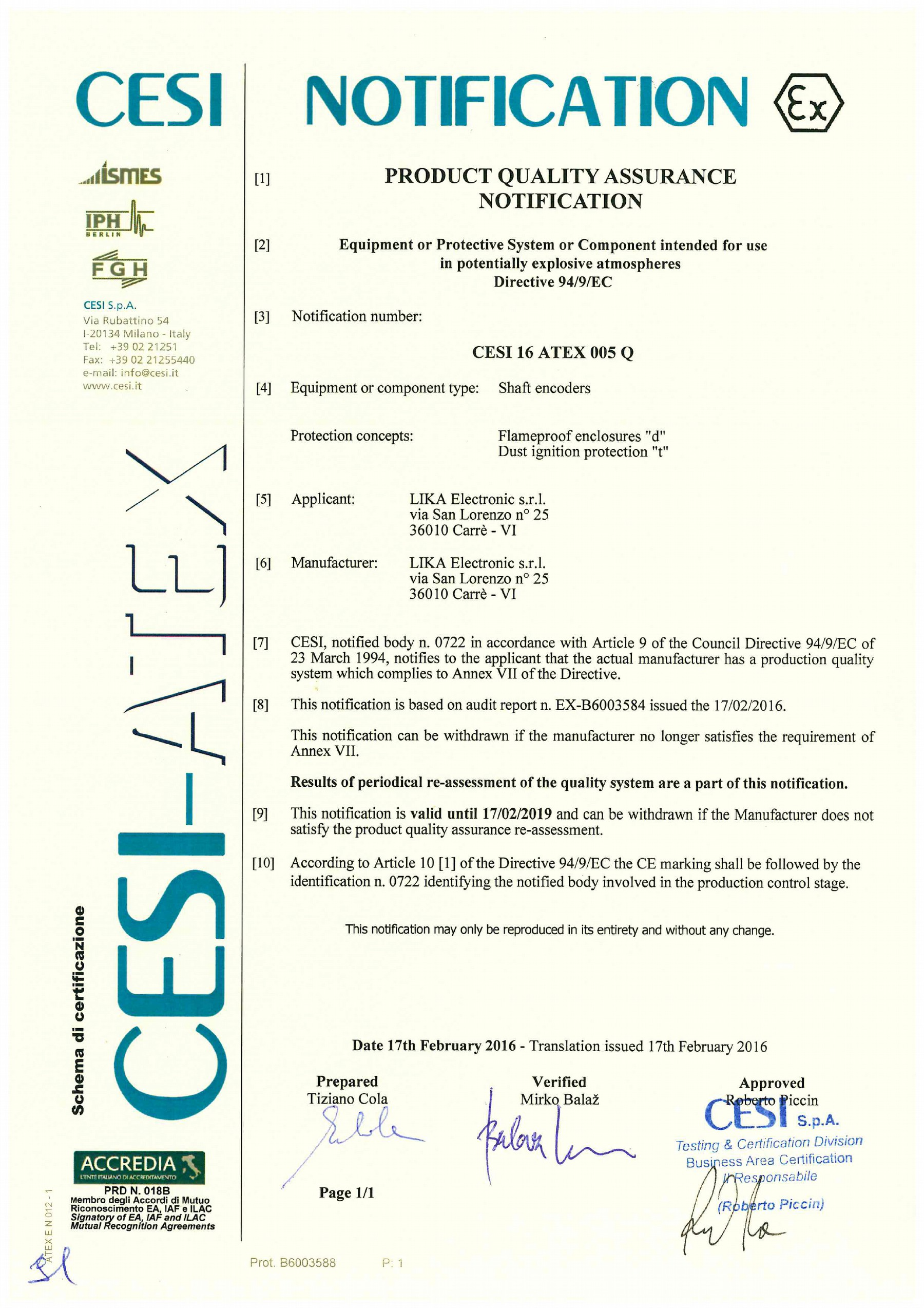
26 Versione documento Descrizione Prima stampa Aggiunto capitolo 7.6 Aggiunti capitoli 7.7 e 7.8 Aggiornato capitolo 7 Aggiornato capitolo 7.4 Aggiornato capitolo 7.6 Aggiornato capitolo 7.6 Aggiornati capitoli 7.4, 7.5 Aggiornati capitoli 7.4, 7.5 e 7,6 Aggiunto encoder con camme integrate, capitolo 6.9 XAC77 con camme programmabili (XAC7712/256CS ) Aggiornamento link web Aggiunta sezione Impostazione indirizzo nodo via BUS (servizio SAP55) Aggiornamento encoder uscita analogica e istruzioni di montaggio Aggiornamento certificati ATEX Informazione lunghezza cavo ( 6.1 Lunghezza minima del cavo ) Introduzione versione con interfaccia DeviceNet Aggiornamento certificati ATEX Aggiornamento certificati ATEX Aggiornamento Dichiarazione di Conformità CE Aggiunta Notifica della garanzia di qualità dei prodotti CESI 16 ATEX 005 Q Nuova direttiva ATEX 2014/34/UE e compatibilità elettromagnetica 2014/30/UE, Aggiornamento Dichiarazione di Conformità UE Smaltire separatamente Lika Electronic Via S. Lorenzo, Carrè (VI) - Italy Tel Fax Italy: info@lika.it - World: info@lika.biz -
27 User's manual XC77 XAC77 II2 GD, Ex d IIC T6 Gb, Ex tb IIIC T85 C Db, IP65 II2 GD, Ex d IIB T6 Gb, Ex tb IIIC T85 C Db, IP65 Table of Contents 1 - Safety summary 2 - Identification 3 - ATEX certificate 4 EU Declaration of Conformity 5 Safety instructions 6 - Electrical connections 7 Mechanical characteristics 1 - Safety summary Safety Always comply with the information in this manual concerning the ATEX products; always adhere to the professional safety and accident prevention regulations applicable to your country during device installation and operation; installation and maintenance operations have to be carried out by qualified personnel only, with power supply disconnected and stationary mechanical parts; device must be used only for the purpose appropriate to its design: use for purposes other than those for which it has been designed could result in serious personal and/or the environment damage; high current, voltage and moving mechanical parts can cause serious or fatal injury; failure to comply with these precautions or with specific warnings elsewhere in this manual violates safety standards of design, manufacture, and intended use of the equipment; Lika Electronic assumes no liability for the customer's failure to comply with these requirements. 27
28 Electrical safety Turn off power supply before connecting the device; connect according to explanation in the 6 - Electrical connections section; wires of output signals which are not used must be insulated singularly; absolute encoders: connect Zero setting and Counting Direction inputs to 0Vdc, if not used; - to zero set the encoder, connect Zero setting to +Vdc for 100 µs at least, then disconnect +Vdc; normally voltage must be at 0Vdc; zero set must be performed after Counting Direction; we suggest performing the zero set when the encoder is in stop; - Counting Direction: CW increasing count (viewed from shaft side) = connect to 0Vdc; CCW increasing count = connect to +Vdc; in compliance with the 2014/30/EU norm on electromagnetic compatibility, following precautions must be taken: - before handling and installing, discharge electrical charge from your body and tools which may come in touch with the device; - power supply must be stabilized without noise, install EMC filters on device power supply if needed; - always use shielded cables (twisted pair cables whenever possible); - avoid cables runs longer than necessary; - avoid running the signal cable near high voltage power cables; - mount the device as far as possible from any capacitive or inductive noise source, shield the device from noise source if needed; - to guarantee a correct working of the device, avoid using strong magnets on or near by the unit; - minimize noise by connecting the shield and/or the frame to ground. Make sure that ground is not affected by noise. The connection point to ground can be situated both on the device side and on the installation side. The best solution to minimize the interference must be carried out by the user. Mechanical safety Install the device following strictly the information in the 7 Mechanical characteristics section; mechanical installation has to be carried out with stationary mechanical parts; do not disassemble the encoder; do not tool the encoder or its shaft; delicate electronic equipment: handle with care; do not subject the device and the shaft to knocks or shocks; respect the environmental characteristics declared by manufacturer; unit with hollow shaft: the encoder can be mounted directly on a shaft whose diameter has to meet the technical characteristics specified in the purchase order and clamped by means of the collar. 2 - Identification Device can be identified through the order code and the serial number printed on the label applied to its body. Information is listed in the delivery document too. Please always quote the ordering code and the serial number when reaching Lika Electronic for purchasing spare parts or needing assistance. For any information on the technical characteristics of the product refer to the technical catalogue. 28

29 3 - ATEX certificate 29
30 30
31 31
32 32
33 33
34 34
35 35
36 4 EU Declaration of Conformity 36
37 5 Safety instructions 37
38 38

39 6 - Electrical connections WARNING Turn off the power supply before connecting the device. WARNING If wires of unused signals come in contact, irreparable damage could be caused to the device. Please insulate them singularly. Minimize noise by connecting the shield and/or the frame to ground. Make sure that ground is not affected by noise. The connection point to ground can be situated both on the device side and on the installation side. The best solution to minimize the interference must be carried out by the user. 6.1 Minimum cable length XC and XAC devices are provided with a cable having a minimum length of 3 m in order to meet the gas protection requirements and thus bear the ATEX marking: II2 GD Ex d IIC T6 Gb. Do not shorten the cable! If this happens, the gas protection level cannot be reached and the ATEX marking has to be intended as follows: II2 GD Ex d IIB T6 Gb (lower gas protection level). 6.2 XC77- -ZCU Function A /A B /B 0 /0 +Vdc 0Vdc power supply Shielding 8-wire I8 type cable Yellow Blue Green Orange White Grey Red Black Shield 39

40 6.3 XAC77 with SSI interface Function Clock + Clock Data + Data Zero setting Counting Direction +10Vdc +30Vdc 0Vdc power supply Shielding 8-wire A8 type cable White Brown Green Yellow Pink Blue Red Black Shield 40
 Function 16-wire A16 cable 19-wire A19 cable 32-wire A32 cable Brown Brown Brown 1 LSB Red Red Red 2 Pink Pink Pink 3 Yellow Yellow Yellow 4 Green Green Green 5 Blue Blue Blue 6 Violet")
41 6.4 XAC77 with bit parallel output (NPN o.c. / Push-Pull) Function 16-wire A16 cable 19-wire A19 cable 32-wire A32 cable Brown Brown Brown 1 LSB Red Red Red 2 Pink Pink Pink 3 Yellow Yellow Yellow 4 Green Green Green 5 Blue Blue Blue 6 Violet Violet Violet 7 Grey Grey Grey 8 White White White 9 Black Black Black 10 White/Green White/Green Brown/Red 11 Brown/Green Brown/Green White/Red 12 Red/Blue Red/Blue 13 Grey/Brown Grey/Pink 14 White/Grey White/Yellow 15 Brown/Green 16 White/Green 17 Yellow/Brown 18 White/Blue 19 Brown/Blue 20 White/Pink 21 White/Grey 22 Pink/Brown 23 Grey/Brown 24 Brown/Black 25 Red/Blue White/Pink Grey/Green Zero setting Grey/Pink Grey/Pink Yellow/Pink Counting Direction White/Yellow White/Yellow Green/Blue +10Vdc +30Vdc Yellow/Brown Yellow/Brown Yellow/Blue 0Vdc power supply Shield Shield Shield Shielding 41
42 6.5 XAC77 with Profibus-DP interface (XAC77xx/xxxxxPB-...) ATEX encoders with Profibus interface are based on the Hx58 FB series encoders, thus refer to the transmission specifications described in the Hx58 FB Profibus manual; differences, if any, are described below. Furthermore they need the HS58_Vx.gsd (singleturn) or HM58_Vx.gsd (multiturn) GSD file. User's manual and GSD file are available at the address: > PRODUCTS > ROTARY ENCODERS > ABSOLUTE ENCODERS > PROFIBUS > Hx58 FB). Function +10Vdc +30Vdc Supply voltage 0Vdc Supply voltage Wires Red White Profibus B (bus input) Profibus A (bus input) Blue White Profibus B (bus output) Profibus A (bus output) Green White +5Vdc out for RT1 0Vdc out for RT1 Yellow White Profibus Shielding Shield 1 Both wires are supplied with a heat-shrink tubing protection; ensure it is always applied over them if the bus termination resistor is not provided (Danger! Irreparable damages!). WARNING The node address must be set via software by the bus Master using the SAP55 service, for further information refer to the Setting the node address via BUS (SAP55 service) section on page 43. Node address = 125 is set by Lika Electronic by default; to set a different address you must connect to the network one encoder at a time and then set the node ID, otherwise an address conflict will occur. With /AABT order code (see datasheet), AA address cannot be modified (except AA = 7Eh). Baud rate is set automatically by the bus Master. Do not open the device for any setting! The diagnostic LEDs are not available for this model. Provided cable is not a Profibus certified cable, anyway it is fitted with bus input and output to avoid installing stubs on the Profibus network. If the encoder is either the first or the last in the transmission line (at the ends of the network), a certified bus active termination resistor must be installed; otherwise the following connection must be provided at outputs. With /AABT order code (see datasheet), if T = 1, the termination resistor is installed and active and cannot be deactivated (do not install external resistors!). To avoid irreparable damages to the encoder wires which are not used must be cut at different lengths and insulated singularly. 42
, AA address cannot be modified (except AA = 7Eh).")
43 6.5.1 Setting the node address via BUS (SAP55 service) WARNING SAP55 service can only be accomplished by a Class 2 DP Master (DPM2). Class 1 Masters (DPM1) cannot accomplish the SAP55 service. With /AABT order code (see datasheet), AA address cannot be modified (except AA = 7Eh). Lika encoders of the XAC77 series are designed to allow the slave address setting via a bus command by means of the SAP55 service. The Service Access Point SAP55 Set_Slave_Address allows to change the address stored in the internal memory of a slave device. SAP55 service is part of the Profibus specifications and allows to change the internal memory address in the event that the device does not provide switches for setting its address or they are not usable. The internal memory address stored at factory by Lika Electronic is 125. Setting the node address via Siemens STEP7 To change the node address stored in the internal memory, open the SIMATIC Manager window and press the Assign PROFIBUS Address command in the PLC\PROFIBUS menu. The Assign PROFIBUS Address window will appear on the screen. In the Assign PROFIBUS Address window select the node address currently stored in the internal memory (factory setting = 125) in the Current PROFIBUS Address combo box and then select the new address you want to set in the New PROFIBUS Address combo box (for instance: 6 ). Press the Apply button and then the OK button to confirm. 43
44 6.6 XAC77 with CANopen interface (XAC77xx/xxxxxCB-...) ATEX encoders with CANopen interface are based on the Hx58 FB series encoders, thus refer to the transmission specifications described in the Hx58 FB CANopen manual; differences, if any, are described below. Furthermore they need the Lika_HSxCB_DS406_Vx.eds (singleturn) or Lika_HMxCB_DS406_Vx.eds (multiturn) EDS file. User's manual and EDS file are available at the address: > PRODUCTS > ROTARY ENCODERS > ABSOLUTE ENCODERS > CAN > Hx58 FB). Function +10Vdc +30Vdc Supply voltage 0Vdc Supply voltage Wires Red White CAN L (bus input) CAN H (bus input) Blue White CAN L (bus output) CAN H (bus output) Green White Not used Not used Yellow White CAN Shielding Shield WARNING The node address and the baud rate must be set via software by the bus Master (see objects 3000h e 3001h in the Object dictionary section of the enclosed Hx58 FB CANopen manual). Node address = 1 and baud rate = 500 Kbit/s are set by Lika Electronic by default; to set a different address you must connect to the network one encoder at a time and then set the node ID, otherwise an address conflict will occur. With /AABT order code (see datasheet), AA address (except AA = 7Eh) and B baud rate (except B = Z) cannot be modified. Do not open the device for any setting! The diagnostic LEDs are not available for this model. Provided cable is not a CANopen certified cable, anyway it is fitted with bus input and output to avoid installing stubs on the CANopen network. If the encoder is either the first or the last in the transmission line (at the ends of the network), the bus termination resistor must be provided outside the device (120 bus termination resistor between CAN High and CAN Low outputs) as shown in the scheme. With /AABT order code (see datasheet), if T = 1, the termination resistor is installed and active and cannot be deactivated (do not install external resistors!). To avoid irreparable damages to the encoder wires which are not used must be cut at different lengths and insulated singularly. 44
45 6.7 XAC77 with DeviceNet interface (XAC77xx/xxxxxFD-...) ATEX encoders with DeviceNet interface are based on the Hx58 FB series encoders, changes are described below; refer to the transmission specifications described in the Hx58 FB DeviceNet manual; differences, if any, are described below. Furthermore they need the Lika_HS58x_FDV_Vx.eds (singleturn) or Lika_HM58x_FDV_Vx.eds (multiturn) EDS file. User's manual and EDS file are available at the address: > PRODUCTS > ROTARY ENCODERS > ABSOLUTE ENCODERS > DEVICENET > Hx58 FB). Function +10Vdc +30Vdc Supply voltage 0Vdc Supply voltage Wires Red White CAN L (bus input) CAN H (bus input) Blue White CAN L (bus output) CAN H (bus output) Green White Not used Not used Yellow White CAN Shielding Shield WARNING Do not open the device for any setting! The diagnostic LEDs are not available for this model. Provided cable is not a CANopen certified cable, anyway it is fitted with bus input and output to avoid installing stubs on the CANopen network. To avoid irreparable damages to the encoder wires which are not used must be cut at different lengths and insulated singularly. The node address (00hex 3Fhex) is pre-set at Lika premises according to the order code shown in the table a below; value is expressed in hex. The baud rate is pre-set at Lika according to the order code shown in the table a below. The bus termination resistor (necessary if the encoder is either the first or the last in the transmission line, i.e. at the ends of the network) is pre-set at Lika premises according to the order code shown in the table a below. As an alternative the termination resistor can be provided outside the device (120 resistor between CAN High and CAN Low outputs) as shown in the following scheme b: a XAC77xx/xxxxxFD-xx-xxx/aabt b aa: node address (hex) b: baud rate 00hex 3Fhex (00 63) D = 125 kbit/s E = 250 kbit/s F = 500 kbit/s t: termination resistor 0 = deactivated 1 = activated EXAMPLE: XAC77xx/xxxxxFD-xx-xxx/0DD0 0D= node address 0Dhex (13dec); D = baud rate 125 kbit/s 0 = termination resistor deactivated 45
46 6.8 XAC77 with analogue output ATEX encoders with analogue output are based on the EM58 PA series programmable encoders, thus refer to the transmission specifications described in the enclosed EM58 PA manual; differences, if any, are described below. Furthermore they need the programming interface tool for configuration. User's manual and programming file are available at the address: > PRODUCTS > ROTARY ENCODERS > ABSOLUTE ENCODERS > ANALOGUE OUTPUT > EM58 PA). Function TxD (RS232) * RxD (RS232) * 0Vdc (RS232) Fault +Iout 0Vdc Analog +Vout Counting Direction Preset (Zero setting) +13Vdc +30Vdc 0Vdc power supply Shielding T12 cable Red Green Brown Yellow Gray Violet Pink Blue White Brown/Green White/Green Shield * Make sure that RxD on PC side is connected with TxD on device side and TxD / PC is connected with RxD / device Description 0Vdc Analog signal is internally connected to 0Vdc. Preset: Data latch in memory (active high for at least 100 ms). Counting Direction: set counter clockwise (active high). Fault: Open collector signal for cable integrity check (only current output). To connect fault signal refer to Figure 2 and Figure 3, pay attention to the value of R2. No enc. error = transistor ON (in conduction). Encoder error = transistor OFF (open). 46
47 Fault connected to a PLC input Fault connected to a relay Imax = 50mA R1 = 47 Vdc R2 R1 I Fig. 2 Fig. 3 Example 1K < R2 < 10K No encoder error = PLC input Low (0 Vdc). Encoder error = PLC input High (+Vdc). Example Vdc = +24V I = 30mA (current necessary to energize the coil of a small relay) R2 = 750 No encoder error = coil energized. Encoder error = coil not energized. 47
 ATEX encoders with integrated cam switch programmer are based on the AMR58/AMRC series encoders; differences, if any, are described below.")
48 6.9 XAC77 with integrated cam switch programmer (XAC7712/256CS ) ATEX encoders with integrated cam switch programmer are based on the AMR58/AMRC series encoders; differences, if any, are described below. For any information on the the communication characteristics and programming the encoder please refer to the documentation of the AMR58 series encoder at the address: > PRODUCTS > ROTARY ENCODERS > ABSOLUTE ENCODERS > AMR58). Function OUT 1 OUT 2 OUT 3 OUT 4 OUT 5 OUT 6 OUT 7 OUT 8 Data OUT + Data OUT Clock IN + Clock IN Load Program Select Program 20 (1) Select Program 21 (1) Select Program 22 (1) Select Program 23 (1) Fault RxD RS-232 (2) TxD RS-232 (2) 0Vdc (3) 0Vdc RS-232 (4) Zero setting Counting Direction +10Vdc +30Vdc Power supply 0Vdc Power supply (3) Shielding A32 cable Brown Red Pink Yellow Green Blue Violet Grey Blue/Red Pink/Grey White/Yellow Brown/Green White/Green Yellow/Brown White/Blue Brown/Blue White/Pink White/Grey Pink/Brown Grey/Brown Brown/Black White/Black Grey/Green Yellow/Pink Green/Blue + Pink/Green Yellow/Blue + Yellow/Grey Shield NOTE 1. Program selection inputs (Select Program) are internally connected to 0Vdc through pulldown resistors. They are active at +Vdc. 2. Please always make sure that the RxD of the ENCODER is cross-wired to the TxD of the PC while the TxD is cross-wired to the RxD. 3. 0Vdc and 0Vdc Power supply are internally connected. 4. 0Vdc RS-232 is internally insulated from 0Vdc Power supply. 48
49 7 Mechanical characteristics 7.1 XC77 incremental encoder 7.2 XAC77 absolute encoder 49
50 7.3 Solid shaft (LKM-1758) and Fixing plate (LKM-1520) LKM-1758 is an optional feature thus it has to be ordered separately. WARNING Unit with solid shaft: in order to guarantee maximum reliability over time of the mechanical parts, we recommend a flexible coupling to be installed to connect the encoder and the installation shaft; make sure the misalignment tolerances of the flexible coupling are respected. 7.4 Mounting instructions WARNING Installation and maintenance operations have to be carried out by qualified personnel only, with power supply disconnected and mechanical parts absolutely in stop. Fasten the fixing plate 1 to the encoder using the three M4 screws 2 provided with the device; mount the encoder on the motor shaft using the reducing sleeve (if supplied); avoid forcing the encoder shaft; fasten the fixing plate 1 to the rear of the motor using four M4 cylindrical head screws 3; fix the collar 4 to the encoder shaft. 50
51 This page intentionally left blank
52 Document release Description 1st issue Adding section 7.6 Adding sections 7.7 and 7.8 Updating section 7 Updating section 7.4 Updating section 7.6 Updating section 7.6 Updating sections 7.4 and 7.5 Updating sections 7.4, 7.5 and 7.6 Added information on cam switch encoder (6.9 XAC77 with integrated cam switch programmer (XAC7712/256CS ) section) Web links updated Setting the node address via BUS (SAP55 service) section updated Analogue encoder information and mounting instructions updated ATEX certificates update Information about cable length added ( 6.1 Minimum cable length ) DeviceNet interface version added ATEX certificates update ATEX certificates update Declaration of CE Conformity update Product Quality Assurance notification CESI 16 ATEX 005 Q added New ATEX directive 2014/34/EU and electromagnetic compatibility 2014/30/EU, EU Declaration of Conformity update Dispose separately Lika Electronic Via S. Lorenzo, Carrè (VI) - Italy Tel Fax Italy: info@lika.it - World: info@lika.biz -
XC77 XAC77. Manuale d uso. Elenco sezioni. 1 - Norme di sicurezza. XC77 XAC77 - encoder ATEX
 Manuale d uso XC77 XAC77 Elenco sezioni 1 - Norme di sicurezza 2 - Identificazione 3 - Certificato ATEX 4 - Dichiarazione CE 5 - Nota tecnica 6 - Istruzioni di sicurezza 7 - Connessioni elettriche 8 -
SFE. Manuale d uso. 1 - Norme di sicurezza. Elenco sezioni SFE
 Manuale d uso 1 - Norme di sicurezza Sicurezza Durante l installazione e l utilizzo del dispositivo osservare le norme di prevenzione e sicurezza sul lavoro previste nel proprio paese; l installazione
CONFIGURATION MANUAL
 RELAY PROTOCOL CONFIGURATION TYPE CONFIGURATION MANUAL Copyright 2010 Data 18.06.2013 Rev. 1 Pag. 1 of 15 1. ENG General connection information for the IEC 61850 board 3 2. ENG Steps to retrieve and connect
Alimentatori per LED di segnalazione (MINILED) Power supply units for Signal LEDs (MINILED)
 Power supply units for Signal LEDs (MINILED)") Alimentatori per LED di segnalazione (MINILED) Power supply units for Signal LEDs (MINILED) Alimentatori elettronici con tensione di uscita stabilizzata per moduli LED di segnalazione. Led driver with
Alimentatori per LED di segnalazione (MINILED) Power supply units for Signal LEDs (MINILED) Alimentatori elettronici con tensione di uscita stabilizzata per moduli LED di segnalazione. Led driver with
U/D (SELEZIONE UP/DOWN) U/D (UP/DOWN SELECTION )
 U/D (UP/DOWN SELECTION )") U/D (SELEZIONE UP/DOWN) U/D (UP/DOWN SELECTION ) Caratteristiche di funzionamento up/down - segnale di input ROTAZIONE DELL ALBERO IN SENSO ORARIO (CW) (Fig 21) Il segnale Alto ("HIGH") applicato al pin
U/D (SELEZIONE UP/DOWN) U/D (UP/DOWN SELECTION ) Caratteristiche di funzionamento up/down - segnale di input ROTAZIONE DELL ALBERO IN SENSO ORARIO (CW) (Fig 21) Il segnale Alto ("HIGH") applicato al pin
REGISTRATION GUIDE TO RESHELL SOFTWARE
 REGISTRATION GUIDE TO RESHELL SOFTWARE INDEX: 1. GENERAL INFORMATION 2. REGISTRATION GUIDE 1. GENERAL INFORMATION This guide contains the correct procedure for entering the software page http://software.roenest.com/
E.1 Distinzione conduttori in relazione alla funzione colors of conductors according to their function
 APPENDICE - APPENDIX Appendice E. Appendix E. Tabelle colore Tables of E.1 Distinzione conduttori in relazione alla funzione colors of conductors according to their function Tabella E.1. i dei conduttori
WIN 3 / PROFIBUS. Amplificatore digitale per celle di carico con interfaccia PROFIBUS DP-V1... ITALIANO [Pag. 2-3]
![WIN 3 / PROFIBUS. Amplificatore digitale per celle di carico con interfaccia PROFIBUS DP-V1... ITALIANO [Pag. 2-3]](/thumbs/39/19784887.jpg "WIN 3 / PROFIBUS. Amplificatore digitale per celle di carico con interfaccia PROFIBUS DP-V1... ITALIANO [Pag. 2-3]") WIN / PROFIBUS Amplificatore digitale per celle di carico con interfaccia PROFIBUS DP-V1... ITALIANO [Pag. -] Load cells digital amplifier with PROFIBUS DP-V1 interface... ENGLISH [Pag. 4-5] Display di
WIN / PROFIBUS Amplificatore digitale per celle di carico con interfaccia PROFIBUS DP-V1... ITALIANO [Pag. -] Load cells digital amplifier with PROFIBUS DP-V1 interface... ENGLISH [Pag. 4-5] Display di
Guida all utilizzo del modulo MPI BrainChild
 Document version: 1.0 easitec S.r.l. Viale Martiri della Benedicta, 102 15069 Serravalle Scrivia (AL) - Italy Phone +39.0143.686023 - Fax +39.0143.634777 info@easitec.it - www.easitec.it Revision History
SOMMARIO GENERALITÀ 3 AGGIORNAMENTO FIRMWARE 4 PROGRAMMAZIONE DEL MICROPROCESSORE 7 AGGIORNAMENTO MULTICOM 302 / 352 4 AGGIORNAMENTO MULTI I/O 5
 MultiCOM - Mult lti I/O - Remote Panel - Istruzioni aggiornamento firmware - - Firmware upgrade instructions - SOMMARIO GENERALITÀ 3 AGGIORNAMENTO FIRMWARE 4 AGGIORNAMENTO MULTICOM 301 / 351 4 AGGIORNAMENTO
LO LH BUSREP. 1 2 3 Jp2. Jp1 BUSREP. Ripetitore di linea seriale RS 485 Manuale d installazione RS 485 Serial Line Repeater Instruction Manual
 Jp MS 4 LINEA 4 MS MS LINEA LINEA Tx4 Tx Tx Tx BUSREP S Jp Jp LINEA GND +,8 Jp4 BUSREP Ripetitore di linea seriale RS 485 Manuale d installazione RS 485 Serial Line Repeater Instruction Manual Edizione/Edition.
Guida all installazione del prodotto 4600 in configurazione plip
 Guida all installazione del prodotto 4600 in configurazione plip Premessa Questo prodotto è stato pensato e progettato, per poter essere installato, sia sulle vetture provviste di piattaforma CAN che su
IF10. Manuale d'uso. Descrizione. Elenco sezioni IF10
 Manuale d'uso IF10 Descrizione IF10 è un commutatore d'impulsi, ripartitore e separatore di segnali per encoder incrementali. Questa interfaccia universale per encoder si presta a un utilizzo come convertitore
Mod. 1067 INTERFACCIA USB/KEY USB/KEY INTERFACE. Sch./Ref.1067/003
 Mod. 1067 DS1067-019 LBT8388 INTERFACCIA USB/KEY USB/KEY INTERFACE Sch./Ref.1067/003 ITALIANO DESCRIZIONE GENERALE L interfaccia 1067/003 consente di collegare alla Centrale 1067/032 o 1067/042 (ver. 2.00
1. Domanda di certificazione da riportare su carta intestata del fabbricante che richiede la certificazione / Certification request To report on
 1. Domanda di certificazione da riportare su carta intestata del fabbricante che richiede la certificazione / Certification request To report on LETTERHEAD PAPER of the applicant 2. Elenco documenti che
Installazione interfaccia e software di controllo mediante PC Installing the PC communication interface and control software
 Windows 7 Installazione interfaccia e software di controllo mediante PC Installing the PC communication interface and control software Contenuto del kit cod. 20046946: - Interfaccia PC-scheda (comprensiva
 MANUALE UTENTE MODULO ESPANSIONE TASTI MANUALE UTENTE MANUALE UTENTE Descrizione Il modulo fornisce al telefono VOIspeed V-605 flessibilità e adattabilità, mediante l aggiunta di trenta tasti memoria facilmente
ELCART. Manuale di istruzioni/scheda tecnica SPECIFICATION
 PAGINA 1 DI 7 SPECIFICATION Customer : ELCART Applied To : Product Name : Piezo Buzzer Model Name : : Compliance with ROHS PAGINA 2 DI 7 2/7 CONTENTS 1. Scope 2. General 3. Maximum Rating 4. Electrical
no. SIC04053.03 Rev. 00 Dated 2008.10.02
 TECHNICAL REPORT RAPPORTO TECNICO no. SIC04053.03 Rev. 00 Dated 2008.10.02 This technical report may only be quoted in full. Any use for advertising purposes must be granted in writing. This report is
User Guide Guglielmo SmartClient
 User Guide Guglielmo SmartClient User Guide - Guglielmo SmartClient Version: 1.0 Guglielmo All rights reserved. All trademarks and logos referenced herein belong to their respective companies. -2- 1. Introduction
DICHIARAZIONE DI RESPONSABILITÀ
 - 0MNSWK0082LUA - - ITALIANO - DICHIARAZIONE DI RESPONSABILITÀ Il produttore non accetta responsabilità per la perdita di dati, produttività, dispositivi o qualunque altro danno o costo associato (diretto
CEDMEGA Rev 1.2 CONNECTION TUTORIAL
 CEDMEGA Rev 1.2 CONNECTION TUTORIAL rev. 1.0 19/11/2015 1 www.cedelettronica.com Indice Power supply [Alimentazione]... 3 Programming [Programmazione]... 5 SD card insertion [Inserimento SD card]... 7
Guida alla configurazione Configuration Guide
 Guida alla configurazione Configuration Guide Configurazione telecamere IP con DVR analogici, compatibili IP IP cameras configuration with analog DVR, IP compatible Menu principale: Fare clic con il pulsante
Manuale d'uso DIMMER CLL-CH1 DIMMER CLL-CH1 User s Handbook
 Manuale d'uso DIMMER CLL-CH1 DIMMER CLL-CH1 User s Handbook PREMESSA/PREAMBLE "ATTENZIONE: prima di compiere qualsiasi operazione leggere attentamente le istruzioni contenute nel manuale. WARNING: read
± 7 10 mm Risoluzione. 1 mm Emissione LASER rosso (class 2) 30 ms (S85- -Y03) Tempo di risposta 15 45 ms (S85- -Y13) Interfaccia seriale
 30 ms (S85- -Y03) Tempo di risposta 15 45 ms (S85- -Y13) Interfaccia seriale") Sensore LASER di distanza per misure precise fino a 20 m, con un millimetro di risoluzione e ripetibilità, tramite tecnologia Time of Flight Tecnologia Time of flight LASER rosso visibile in classe 2 per
Sensore LASER di distanza per misure precise fino a 20 m, con un millimetro di risoluzione e ripetibilità, tramite tecnologia Time of Flight Tecnologia Time of flight LASER rosso visibile in classe 2 per
IF2E001 Interfaccia Ethernet-RS485
 IF2E001 Interfaccia Ethernet-RS485 Manuale utente File : Ethernet interfaccia-manuale utente.doc 1/4 Interfaccia Ethernet manuale utente Versione 1.1 1 DESCRIZIONE GENERALE Questo dispositivo consente
Quando mi collego ad alcuni servizi hosting ricevo un messaggio relativo al certificato di protezione del sito SSL, come mai?
 IT FAQ-SSL Quando mi collego ad alcuni servizi hosting ricevo un messaggio relativo al certificato di protezione del sito SSL, come mai? Il certificato SSL relativo ai servizi hosting è stato rinnovato
group STRUMENTO CANVIEW 3+ CANVIEW 3+ INSTRUMENT CLUSTER CAN J1939 ISOBUS - ISO11783 VT3 SOFTWARE DEVELOPMENT TOOLS IEC 61131
 group STRUMENTO CANVIEW 3+ CANVIEW 3+ INSTRUMENT CLUSTER IEC 61131 VT3 SOFTWARE DEVELOPMENT TOOLS CAN J1939 ISOBUS - ISO11783 1 STRUMENTO CANVIEW 3+ CANVIEW 3+ INSTRUMENT CLUSTER 2 SPECIFICHE TECNICHE
A3/A6 Displays. Technical Description
 A3/A6 Displays Technical Description Summary A3 ECO... 2 A3 ECO Basic Version: technical specifications... 2 A3 ECO Full Version: technical specifications... 3 A3 STANDARD... 4 A3 STANDARD Basic Version:
group HIGH CURRENT MULTIPLEX NODE
 HIGH CURRENT MULTIPLEX NODE edizione/edition 04-2010 HIGH CURRENT MULTIPLEX NODE DESCRIZIONE GENERALE GENERAL DESCRIPTION L'unità di controllo COBO è una centralina elettronica Multiplex Slave ; la sua
XAC77 Profibus-DP. Manuale d'uso
 Manuale d'uso XAC77 PX Elenco sezioni - Norme di sicurezza - Identificazione 3 - Istruzioni di montaggio 4 - Connessioni elettriche 5 - Quick reference (STEP7 di Siemens) 6 - Interfaccia Profibus Profibus-DP
MANUALE DISPLAY REMOTO CALDAIE REMOTE DISPLAY MANUAL FOR BOILERS
 MANUALE DISPLAY REMOTO CALDAIE REMOTE DISPLAY MANUAL FOR BOILERS COMPATIBILE CON - COMPATIBLE WITH LP14/20/30 SCHEDA - MOTHERBOARD 512 E SW V5 2 IT COLLEGAMENTO A MURO DELLA CONSOLE LCD - CALDAIA Collegamento
SMS11 (1Vpp) Manuale d uso
 Manuale d uso") (1Vpp) Descrizione Manuale d uso Il presente manuale è stato realizzato per la serie di prodotti SMS11. Questi trasduttori di posizione sono stati progettati per realizzare sistemi di misura su macchine
(1Vpp) Descrizione Manuale d uso Il presente manuale è stato realizzato per la serie di prodotti SMS11. Questi trasduttori di posizione sono stati progettati per realizzare sistemi di misura su macchine
Mod. 1067 VIDEO GATEWAY A 4 CANALI 4 CHANNELS VIDEO GATEWAY. Sch./Ref.1067/450
 Mod. 1067 DS1067-017 LBT8386 VIDEO GATEWAY A 4 CANALI 4 CHANNELS VIDEO GATEWAY Sch./Ref.1067/450 Fig. 1 Fig. 2 Fig. 3 Fig. 4 A B A B C D E 2 DS1067-017 ITALIANO DESCRIZIONE GENERALE Modulo video con 4
Compatibilità del Portale Piaggio con Internet Explorer 10 e 11. Internet Explorer 10
 Italiano: Explorer 10 pagina 1, Explorer 11 pagina 2 English: Explorer 10 page 3 and 4, Explorer 11 page 5. Compatibilità del Portale Piaggio con Internet Explorer 10 e 11 Internet Explorer 10 Con l introduzione
ROTACAM AMR58 / AMRC. Manuale d'uso
 Manuale d'uso ROTACAM Descrizione AMR58 è l'encoder ottico multigiro provvisto di otto uscite per camme elettroniche programmabili. Ogni uscita permette di pilotare un diverso dispositivo periferico sfruttando
AMx58x P. Manuale d'uso
 Manuale d'uso Descrizione L'encoder programmabile LIKA è stato concepito per avere la massima flessibilità e poter sostituire pressoché tutte le versioni di encoder assoluti con uscita parallela o seriale
IF10. Manuale d'uso. Descrizione. Elenco sezioni IF10
 IF0 Manuale d'uso IF0 Descrizione IF0 è un commutatore d'impulsi, ripartitore e separatore di segnali per encoder incrementali. Questa interfaccia universale per encoder si presta a un utilizzo come convertitore
Guida rapida di installazione
 Configurazione 1) Collegare il Router Hamlet HRDSL108 Wireless ADSL2+ come mostrato in figura:. Router ADSL2+ Wireless Super G 108 Mbit Guida rapida di installazione Informiamo che il prodotto è stato
8 Aggiornamento firmware
 8 Aggiornamento firmware Questa sezione spiega come aggiornare i firmware dei vari componenti dell FDM-DUO. Le ultime versioni firmware sono disponibili al seguente indirizzo : http://sdr.eladit.com/fdm-duo/firmware
Il sistema M-Bus symphonic di ista
 Il sistema symphonic di ista Istruzioni di installazione e pianificazione Indice 1. Introduzione 2 1.1 Informazioni generali 2 1.2 Norme / letteratura 2 2. Panoramica del sistema 2 2.1 Principio Bus 2
MANUALE D USO E MANUTENZIONE MAINTENANCE AND OPERATING MANUAL ZERO DRAIN
 OMI srl MANUALE D USO E MANUTENZIONE MAINTENANCE AND OPERATING MANUAL ZERO DRAIN Costruito in accordo alle Direttive 2006/95/CE, 2004/108/CE Manufactured accordingly to European Directives 2006/95/CE,
INTERRUTTORI DI PROSSIMITA CAPACITIVI NON AMPLIFICATI NAMUR CAPACITIVE PROXIMITY NAMUR SWITCHES
 INTERRUTTORI DI PROSSIMITA CAPACITIVI NON AMPLIFICATI NAMUR SERIE SERIES KA CAPACITIVE PROXIMITY NAMUR SWITCHES INTERRUTTORI DI PROSSIMITA CAPACITIVI NAMUR CONFORMI ALLE NORME DIN 19234 E CENELEC EN50014-EN50020
INSTALLARE PALLADIO USB DATA CABLE IN WINDOWS XP/ME/2000/98
 rev. 1.0-02/2002 Palladio USB Data Cable INSTALLARE PALLADIO USB DATA CABLE IN WINDOWS XP/ME/2000/98 (tutti i KIT, escluso KIT MOTOROLA V6x-T280) La procedura di installazione del Palladio USB Data Cable
WELCOME. Go to the link of the official University of Palermo web site www.unipa.it; Click on the box on the right side Login unico
 WELCOME This is a Step by Step Guide that will help you to register as an Exchange for study student to the University of Palermo. Please, read carefully this guide and prepare all required data and documents.
Manuale Handbook. Via Torino 16-15020 Piagera di Gabiano (AL) - ITALIA Tel.+ 39 0142 xxxxxx - fax +39 xxxxx. E-mail: support.race@dimsport.
 - ITALIA Tel.+ 39 0142 xxxxxx - fax +39 xxxxx. E-mail: support.race@dimsport.") DIMA 555PRO Manuale Handbook Via Torino 16-15020 Piagera di Gabiano (AL) - ITALIA Tel.+ 39 0142 xxxxxx - fax +39 xxxxx E-mail: supporto.race@dimsport.it E-mail: support.race@dimsport.it http://www.dimsport.it
DIMA 555PRO Manuale Handbook Via Torino 16-15020 Piagera di Gabiano (AL) - ITALIA Tel.+ 39 0142 xxxxxx - fax +39 xxxxx E-mail: supporto.race@dimsport.it E-mail: support.race@dimsport.it http://www.dimsport.it
LAMPEGGIANTI A LED HIGHLIGHT LED BEACONS
 LAMPEGGIANTI A LED HIGHLIGHT LED BEACONS edizione/edition 11-2011 1 CARATTERISTICHE LUNGA DURATA L utilizzo di LED di ultima generazione garantisce una durata del dispositivo superiore a 30.000 ore di
Copyright 2012 Binary System srl 29122 Piacenza ITALIA Via Coppalati, 6 P.IVA 01614510335 - info@binarysystem.eu http://www.binarysystem.
 CRWM CRWM (Web Content Relationship Management) has the main features for managing customer relationships from the first contact to after sales. The main functions of the application include: managing
SYNC 01. Ripetitore di Sincronismo Manuale di installazione. Synchronism Repeater Installation Handbook. Edizione / Edition 1.1
 SYNC 0 Ripetitore di Sincronismo Manuale di installazione Synchronism Repeater Installation Handbook Edizione / Edition. CIAS Elettronica S.r.l. Ed. DICE. DESCRIZIONE.... DESCRIZIONE.... STALLAZIONE....
NDCMB NDCMB MOTORIDUTTORI C.C. AD ASSI ORTOGONALI RARE EARTH D.C. BEVEL HELICAL GEARMOTORS
 Pag. Page Indice Index Caratteristiche tecniche Technical features D2 Designazione Classification D2 Sensi di rotazione Direction of rotation D2 Simbologia Symbols D2 Lubrificazione Lubrication D3 Carichi
Guida utente User Manual made in Italy Rev0
 Guida utente User Manual Rev0 made in Italy Indice/Index Informazioni generali General Info... 3 Guida Rapida per messa in funzione Start Up procedure... 3 Login Login... 3 Significato dei tasti Botton
Posta elettronica per gli studenti Email for the students
 http://www.uninettunouniverstiy.net Posta elettronica per gli studenti Email for the students Ver. 1.0 Ultimo aggiornamento (last update): 10/09/2008 13.47 Informazioni sul Documento / Information on the
DNV BUSINESS ASSURANCE
 DNV BUSINESS ASSURANCE CERTIFICATO CE DI TIPO EC TYPE-EXAMINATION CERTIFICATE Certificato No. / Certificate No. 2666-2013-CE-ITA-ACCREDIA Questo certificato è di 5 pagine / This certificate consists of
Aggiornamento dispositivo di firma digitale
 Aggiornamento dispositivo di firma digitale Updating digital signature device Questo documento ha il compito di descrivere, passo per passo, il processo di aggiornamento manuale del dispositivo di firma
Appendice E - Appendix E PANNELLI FOTOVOLTAICI - PHOTOVOLTAIC PANELS
 Appendice E - Appendix E PANNELLI FOTOVOLTAICI - PHOTOVOLTAIC PANELS I sistemi mod. i-léd SOLAR permettono di alimentare un carico sia in bassa tensione 12-24V DC, sia a 230v AC, tramite alimentazione
Attuatore a relè Manuale di istruzioni
 Attuatore a relè Manuale di istruzioni www.ecodhome.com 1 Sommario 3 Introduzione 4 Descrizione e specifiche prodotto 5 Installazione 6 Funzionamento 6 Garanzia 2 Introduzione SmartDHOME vi ringrazia per
PG5 Starter Training Applicazione File System Daniel Ernst EN02 2012-02-26 Stefano Peracchi IT01 2013-05-20
 PG5 Starter Training Applicazione File System Daniel Ernst EN02 2012-02-26 Stefano Peracchi IT01 2013-05-20 Introduzione Materiale richiesto Notebook o computer Controllore PCD1 E Cavo USB Scheda «Training»
EXPRESS CARD USB 3.0 ExpressCard/34 con 2 porte USB 3.0
 EXPRESS CARD USB 3.0 ExpressCard/34 con 2 porte USB 3.0 MANUALE UTENTE XUSB302EXC www.hamletcom.com Gentile Cliente, La ringraziamo per la fiducia riposta nei nostri prodotti. La preghiamo di seguire le
RotorSospension Cube 12
 RotorSospension Series RotorSospension Cube 12 Progetto Luce s.r.l. Via XX Settembre 50 - Pomaro Monferrato (AL), Italy, 15040 - Email: info@progetto-luce.it RotorSospension Cube 12 Apparecchio a sospensione
INTRODUZIONE CAVI TELEFONICI INTRODUCTION TELEPHONE CABLES
 INTRODUZIONE CAVI TELEFONICI INTRODUCTION TELEPHONE CABLES CAVI TELEFONICI TRECCIOLA DI PERMUTAZIONE. La trecciola di permutazione, disponibile in vari colori, è indicata nei cablaggi telefonici di DROP.
IF60 - IF61. Manuale d'uso. Descrizione. Elenco sezioni IF60 - IF61
 IF60 - IF61 Manuale d'uso IF60 - IF61 Descrizione IF60 - IF61 sono moduli per fibra ottica specificamente progettati per la trasmissione di segnali rilasciati da encoder e sensori incrementali. Questi
SISTEMA COMPLETO DI ILLUMINAZIONE VANO LAMPADA A LED TIPO ILV24 s. COMPARTMENT SYSTEM LIGHTING COMPLETE LED LAMP TYPE ILV24 s
 SISTEMA COMPLETO DI ILLUMINAZIONE VANO LAMPADA A LED TIPO ILV24 s COMPARTMENT SYSTEM LIGHTING COMPLETE LED LAMP TYPE ILV24 s Caratteristiche generali Mean features Lampade a bassa tensione (24Vcc) Lamps
3G HSPA USB MULTIMODEM High Speed Wireless Connectivity MT4211
 3G HSPA USB MULTIMODEM High Speed Wireless Connectivity MT4211 Instructions Manual Introduction Thank you for your purchasing our HSUPA USB modem with TF fl ash card socket. Device is backward compatible
TACTÒ TASTIERA EFFETTO HALL KEY PAD HALL EFFECT
 TACTÒ TASTIERA EFFETTO HALL KEY PAD HALL EFFECT edizione/edition 04-03 DESCRIZIONE DESCRIPTION DESCRIZIONE La nuova tastiera COBO è stata studiata per ottimizzare gli spazi all interno delle cabine moderne.
ECVCON MANUALE DI INSTALLAZIONE INSTALLATION MANUAL
 ECVCON MANUALE DI INSTALLAZIONE INSTALLATION MANUAL INDICE ECVCON Introduzione... pag. 3 Caratteristiche... pag. 4 Messa in funzione... pag. 6 Inserimento della SIM... pag. 6 Connessione al PC per la prima
Replacement of hose carrier chain
 3 1. Bring the boom in horizontal position and make the extension completely retract. 2. Remove the rear panel. 3. Remove the front guard on the boom hood. 4. In case of machine with basket pre-arrangement,
BUDVR4PLUS - BUDVR16PLUS
 BUDVR4PLUS - BUDVR16PLUS 1. GUIDA RAPIDA ALL INSTALLAZIONE Installazione degli HARDDISK Questi due modelli di DVR non vengono forniti con l Hard Disk installato. La dimensione massima dello spazio del
ENPCOM European network for the promotion of the Covenant of Mayors
 ENPCOM European network for the promotion of the Covenant of Mayors Censimento e monitoraggio dei consumi energetici e comportamento dei cittadini Controllo Energetico dei Consumi degli Edifici Monitoraggio
P r o i e t t o r e a L E D E C O S O L A R
 IN COMPLIANCE WITH EN 12352 LH8 P r o i e t t o r e a L E D E C O S O L A R L E D w a r n i n g l i g h t E C O S O L A R Proiettore a LED Basic 201 certificato UNI EN12352 classe L8H predisposto per fissaggio
INSTRUCTION MANUAL Manual override (GR)
") DESCRIZIONE Tutti gli attuatori STI possono essere equipaggiati con comandi manuali per permettere l operatività senza segnale pneumatico di controllo o se si vuole operare manualmente senza segnale di
DESCRIZIONE Tutti gli attuatori STI possono essere equipaggiati con comandi manuali per permettere l operatività senza segnale pneumatico di controllo o se si vuole operare manualmente senza segnale di
SMIx. Manuale d uso. 1 - Norme di sicurezza. Descrizione. Elenco sezioni. SMIx
 SMIx Descrizione Manuale d uso Il presente manuale è stato realizzato per descrivere i prodotti della serie SMIx. Questi trasduttori di posizione sono stati progettati per realizzare sistemi di misura
M12 X-4. Mixer Preamplifier MASTER 5 AUX TUNER TAPE CD 10-15. MAIN OUT 90-245V JACK 50/60Hz 3 T1,25A. R 10 60-20 30 mic. line AUX TUNER TAPE CD
 M12 X-4 Mixer Preamplifier INPUT VOICE VOICE VOICE VOICE CH1 PIOITY A CH PIOITY AUX TUNE TAPE CD MASTE STEEO MAIN OUT M12 X-4 1 1 1 1 1 1-1 +1-1 +1 1 1 1 CHANNE 1 CHANNE 2 CHANNE3 CHANNE 4 SOUCES VOUME
Hyppo Swing gate opener
 Hyppo Swing gate opener - Instructions and warnings for installation and use IT - Istruzioni ed avvertenze per l installazione e l uso - Instructions et avertissements pour l installation et l utilisation
Molle per stampi DIE SPRINGS ISO 10243
 Molle per stampi DIE SPRIGS ISO 10243 2 Die springs Molle per stampi Located in Colnago, Milano TIPCOCIMA S.r.l. is a joint-venture between TIPCO Inc., a global supplier of pierce punches and die buttons
SOFTWARE DI PROGRAMMAZIONE PER ENCODER SERIALI ASINCRONI AMS / ACS / AMM / ACM Versione 1.5 Introduzione
 SOFTWARE DI PROGRAMMAZIONE PER ENCODER SERIALI ASINCRONI AMS / ACS / AMM / ACM Versione. Introduzione Il software, realizzato dal Hohner Automazione s.r.l., permette di effettuare la programmazione dei
Attuatore a relè Manuale di istruzioni
 Attuatore a relè Manuale di istruzioni www.ecodhome.com 1 Sommario 3 Introduzione 4 Descrizione e specifiche prodotto 5 Installazione 6 Funzionamento 6 Garanzia 2 Introduzione SmartDHOME vi ringrazia per
ECVUSBO MANUALE DEL PRODOTTO DEVICE MANUAL
 ECVUSBO MANUALE DEL PRODOTTO DEVICE MANUAL INDICE TABLE OF CONTENTS 1. Introduzione... pag. 3 1. Introduction... pag. 3 2. Requisiti di sistema... pag. 3 1. System requirements... pag. 3 3. Installazione...
ELCART. Manuale di istruzioni/scheda tecnica
 PAGINA 1 DI 5 FEATURES: SLIM LINE TYPE: 75W Constant Voltage LED Power Supply MODEL: 13/23451-00 - 13/23453-00 INSTALLATION: INSULATION CLASS: PROTECTION GRADE: RoHS: Built in Class II IP20 Comply with
DICHIARAZIONE DI RESPONSABILITÀ
 - ITALIANO - DICHIARAZIONE DI RESPONSABILITÀ Il produttore non accetta responsabilità per la perdita di dati, produttività, dispositivi o qualunque altro danno o costo associato (diretto o indiretto) dovuto
MODELLO-MODEL NON CONFORMI AD ALCUNA NORMATIVA DIN/ISO SULLA SICUREZZA DO NOT COMPLY WITH ANY DIN/ISO SAFETY STANDARD
 (IT) ISTRUZIONI D USO NEWMARK/NEWMARK FREE-LOCK (EN) NEWMARK/NEWMARK FREE-LOCK MOUNTING AND SETTING USER GUIDE MODELLO-MODEL NON CONFORMI AD ALCUNA NORMATIVA DIN/ISO SULLA SICUREZZA DO NOT COMPLY WITH
CW-YO Last CW-EX CW-PS ELP I ELP E B-15. 5 m OUTPUT COLLECTOR BOX BOX RACCOLTA INPUT SCBI 8-M8 INPUT COLLECTOR BOX BOX DISTRIBUZIONE OUTPUT SCBO 8-M8
 OUTPUT COLLECTOR BOX BOX RACCOLTA SCBI 8- BOX DISTRIBUZIONE OUTPUT SCBO 8- COLLECTOR BOX EXPANSION PORT N 8 DIGITAL ( ) 5 m N 8 DIGITAL OUTPUT ( 10W - ) 5 m PORT Collector box for 8 digital input connection
Freni idraulici multidisco serie F Hydraulic Multidisc Brakes F Series
 HYDRAULIC COMPONENTS HYDROSTATIC TRANSMISSIONS GEARBOXES - ACCESSORIES Via M.L. King, 6-41122 MODENA (ITALY) Tel: +39 059 415 711 Fax: +39 059 415 729 / 059 415 730 INTERNET: http://www.hansatmp.it E-MAIL:
Hard Disk Drive Duplicator Dock USB 3.0 to SATA HDD Duplicator. StarTech ID: SATDOCK22RU3
 Hard Disk Drive Duplicator Dock USB 3.0 to SATA HDD Duplicator StarTech ID: SATDOCK22RU3 The SATDOCK22RU3 USB 3.0 to SATA Hard Drive Duplicator Dock can be used as a standalone SATA hard drive duplicator,
M12 X-4. Mixer Preamplifier MASTER 5 AUX TUNER TAPE CD 10-15 VOLUME BASS HIGH. MAINOUT 90-245V JACK 50/60 Hz 3 T1,25A. R 10 60-20 30 mic.
 M12 X-4 Mixer Preamplifier INPUT VOICE VOICE VOICE VOICE CH 1 PIOITY A CH PIOITY AUX TUNE TAPE CD MASTE STEEO MAINOUT M12 X-4 1 1 1 1 1 1-1 +1-1 +1 1 1 1 CHANNE 1 CHANNE 2 CHANNE 3 CHANNE4 SOUCES VOUME
GstarCAD 2010 Features
 GstarCAD 2010 Features Unrivaled Compatibility with AutoCAD-Without data loss&re-learning cost Support AutoCAD R2.5~2010 GstarCAD 2010 uses the latest ODA library and can open AutoCAD R2.5~2010 DWG file.
Calcolo efficienza energetica secondo Regolamento UE n. 327/2011 Energy efficiency calculation according to EU Regulation no.
 Calcolo efficienza energetica secondo Regolamento UE n. 327/2011 Energy efficiency calculation according to EU Regulation no. 327/2011 In base alla direttiva ErP e al regolamento UE n. 327/2011, si impone
POWERGATE-S USER GUIDE
 POWERGATE-S USER GUIDE 1 POWERGATE-S USER GUIDE Introduzione Powergate-S Il più efficace tool per potenziare le qualità del tuo veicolo, attraverso la presa OBDII è in grado di programmare la nuova mappatura
Manuale utente. User s manual 0MNU020NPA
 MultiCOM 351-352 Manuale utente - User s manual 0MNU020NPA IINTRODUZIIONE Vi ringraziamo per la scelta di un prodotto della gamma MultiCOM. Gli accessori descritti in questo manuale sono prodotti di alta
wi fi connection Up to 5h duration 30 fittings controlled SISTEMA DI SUPERVISIONE CENTRALIZZATA Wi-Fi DELL IMPIANTO DI EMERGENZA
 wi fi connection Up to 5h duration 30 fittings controlled SPYMICRO PROGRAMMATION MANUAL VER. 2.0 SISTEMA DI SUPERVISIONE CENTRALIZZATA Wi-Fi DELL IMPIANTO DI EMERGENZA Pag.1-16 WI-FI CENTRALIZED SUPERVISION
TIAN XIA 500 fluo. Product presentation
 TIAN XIA 500 fluo Product presentation Pregnana Milanese, January 2010 1 TIAN XIA 500 fluo design Carlotta de Bevilacqua Lampada a sospensione Con un diametro di 50 cm è la versione di dimensioni più contenute
INFORMAZIONE AGLI UTENTI DI APPARECCHIATURE DOMESTICHE O PROFESSIONALI
 INFORMAZIONE AGLI UTENTI DI APPARECCHIATURE DOMESTICHE O PROFESSIONALI Ai sensi dell art. 13 del Decreto Legislativo 25 luglio 2005, n. 151 "Attuazione delle Direttive 2002/95/CE, 2002/96/CE e 2003/108/CE,
AUTOMAZIONI PER PORTE BATTENTI
 AUTOMAZIONI PER PORTE BATTENTI AUTOMATIONS FOR SWING DOORS Modernità, compattezza ed affidabilità: tre semplici concetti che riassumono al meglio le automazioni per porte battenti myone. Se a queste caratteristiche
Combinazioni serie IL-MIL + MOT
 Combinazioni tra riduttori serie IL-MIL e MOT Combined series IL-MIL + MOT reduction units Combinazioni serie IL-MIL + MOT Sono disponibili varie combinazioni tra riduttori a vite senza fine con limitatore
Driver per LED EcoSystem
 Panoramica 369341c 1 6..14 Il driver ad alte prestazioni per LED EcoSystem consente la dimmerazione regolare e continua fino all 1% con pressoché tutti i tipi di luminari LED, sia che richiedano corrente
UNIVERSITÀ DEGLI STUDI DI TORINO. Instructions to apply for exams ONLINE Version 01 updated on 17/11/2014
 Instructions to apply for exams ONLINE Version 01 updated on 17/11/2014 Didactic offer Incoming students 2014/2015 can take exams of courses scheduled in the a.y. 2014/2015 and offered by the Department
How to use the WPA2 encrypted connection
 How to use the WPA2 encrypted connection At every Alohawifi hotspot you can use the WPA2 Enterprise encrypted connection (the highest security standard for wireless networks nowadays available) simply
GS6A GS6A SERIES TECHNICAL CATALOGUE CATALOGO TECNICO SERIE GS6A 160647.5. Potenza di picco (²) Peso approssimativo unità Capacità olio motore
 Peso approssimativo unità Capacità olio motore") GS6A 1700 2100* 2500 Displacement Cilindrata [cc/rev] 1690 2127 2513 Bore Alesaggio [mm] 82 92 100 Stroke Corsa [mm] 64 Specific torque Coppia specifica [Nm/bar] 26,90 33,86 40,00 Peak pressure Pressione
GS6A 1700 2100* 2500 Displacement Cilindrata [cc/rev] 1690 2127 2513 Bore Alesaggio [mm] 82 92 100 Stroke Corsa [mm] 64 Specific torque Coppia specifica [Nm/bar] 26,90 33,86 40,00 Peak pressure Pressione
Ax58x CB CC-CB, CC-CB-C
 Manuale d'uso Ax58x CB CCCB, CCCBC Elenco sezioni 1 2 3 4 5 6 7 Norme di sicurezza Identificazione Istruzioni di montaggio Quick reference Connessioni elettriche Interfaccia CANopen Programmazione DS406
Serie BL diametro 28 mm con elettronica integrata per regolazione velocità. 28 mm diameter, BL series + integrated speed controller
 Motore CC brushless Serie BL diametro 28 mm con elettronica integrata per regolazione velocità Brushless DC Motor 28 mm diameter, BL series + integrated speed controller Dimensioni Dimensions Specifiche
XIAO TET. parete / wall. halo. Carlotta de Bevilacqua 2007 CLASSE I - IP 20
 XIAO TET parete / wall Carlotta de Bevilacqua 2007 halo CLASSE I - IP 20 IT EN Avvertenze La sicurezza elettrica di questo apparecchio è garantita con l uso appropriato di queste istruzioni. Pertanto è