cilindri oleodinamici hydraulic cylinders catalogo tecnico technical catalog
|
|
|
- Aurelia Ferrara
- 5 anni fa
- Visualizzazioni
Transcript


1 cilindri oleodinamici hydraulic cylinders catalogo tecnico technical catalog
2 0 - Copyright PSSTM Aggiornamenti su / updates on


3 CILINDRI IDRAULICI ISO 0/ a tiranti tie-rods ISO 0/ DRAULIC CLINDRS CILINDRI IDRAULICI ISO 0/ con controflange COUNTR FLANS ISO 0/ DRAULIC CLINDRS SRVOCILINDRI ISO 0/ ISO 0/ SRVOCLINDRS CILINDRI IDRAULICI ISO ISO DRAULIC CLINDRS SRVOCILINDRI ISO ISO SRVOCLINDRS ACCSSORI PR CILINDRI IDRAULICI ISO ACCSSORIS FOR ISO DRAULIC CLINDRS 0- CILINDRI IDRAULICI COMPATTI leggeri LIT COMPACT DRAULIC CLINDRS CILINDRI IDRAULICI COMPATTI PR IMPII RAVOSI AV DUT COMPACT DRAULIC CLINDRS ATTUATORI ROTANTI ROTAR ACTUATORS TABLL TCNIC TCNICAL TABLS Copyright PSSTM Aggiornamenti su / updates on

4 Aggiornamenti su / updates on Copyright PSSTM
5 - CILINDRI IDRAULICI ISO 0/ a tiranti tie-rods ISO 0/ DRAULIC CLINDRS CARATTRISTIC TCNIC TCNICAL CARACTRISTICS ANCORAI MOUNTIN DIMNSIONI DIMNSION STRMITà STLO ROD ND codic di ordinazione ordering code opzioni OPTIONS Piastre incorporate Incorporated plates SNSORI DI PROSSIMITà PROXIMIT SWITCS SNSORI MANTICI MANTIC SWITCS CILINDRI IDRAULICI ISO 0/ CON CONTROFLAN WIT COUNTR FLANS ISO 0/ DRAULIC CLINDRS CARATTRISTIC TCNIC TCNICAL CARACTRISTICS ANCORAI MOUNTIN DIMNSIONI DIMNSION STRMITà STLO ROD ND codic di ordinazione ordering code opzioni SNSORI DI PROSSIMITà OPTIONS and PROXIMIT SWITCS Piastre incorporate Incorporated plates SRVOCILINDRI ISO 0/ ISO 0/ SRVOCLINDRS CARATTRISTIC TCNIC TCNICAL CARACTRISTICS codic di ordinazione ordering code 6 7 ACCSSORI PR CILINDRI IDRAULICI ISO ACCSSORIS FOR ISO DRAULIC CLINDRS CARATTRISTIC TCNIC TCNICAL CARACTRISTICS 0 - Copyright PSSTM Aggiornamenti su / updates on 0-

 Tie rods hydraulic cylinder, in compliance with the ISO 0/ standard, also available with magnetic sensors.")
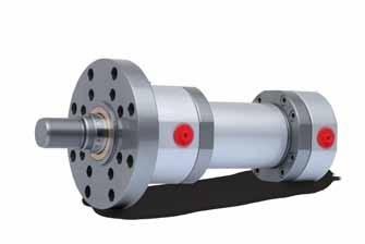
6 CILINDRI IDRAULICI ISO 0/ A TIRANTI TI-RODS ISO 0/ DRAULIC CLINDRS CARATTRISTIC TCNIC TCNICAL CARACTRISTICS Cilindri idraulici a tiranti, conformi alla normativa ISO 0/, anche per uso con sensori magnetici. Disponibili in tutti gli ancoraggi previsti dalla normativa, in molteplici configurazioni di guarnizioni. Tutti i cilindri sono testati prima della consegna in conformità alla normativa ISO 000. Per corse superiori a 000 mm, è consigliabile scegliere la serie D / K (vedi pagina 6) Tie rods hydraulic cylinder, in compliance with the ISO 0/ standard, also available with magnetic sensors. All standard ISO mountings are available, in different seals configurations. All cylinders are tested in compliance with the ISO 000 standard. In case of stroke longer that 000 mm, we recommend the use of the cylinders series D / K (see page 6). CD/DK Caratteristiche tecniche / Specifications Cilindri a norma Standard cylinders Alesaggi Bore Pressione Pressure mm bar ISO 0/ - DIN 5 a tiranti / tie rods da 5 a 00 from 5 to 00 nominale operating CD max 0 da 5 a 00 from 5 to 00 DK Corsa massima Max stroke mm 000 Tolleranza sulla corsa Stroke tolerance 0 + mm Norma ISO 8 ISO 8 Standard Fluido Fluid Olio idraulico minerale / ydraulic mineral oil steri fosforici / Phosphoric esters Acqua glicole / FC-fluid Viscosità Viscosity... mm /S MD MANTICO / MANTIC Caratteristiche tecniche / Specifications Cilindri a norma Standard cylinders ISO 0/ DIN 5 a tiranti / tie rods Alesaggi da 5 a 5 Bore mm from 5 to 5 Pressione Pressure bar max Temperatura fluido Fluid temperature C Compatibilmente con i limiti di temperatura d esercizio dei sensori magnetici. Compatibly with magnetic proximity switches operating temperature limits. Corsa massima Max stroke mm 000 Tolleranza sulla corsa 0 + mm Norma ISO 8 Stroke tolerance ISO 8 Standard Fluido Olio idraulico minerale / ydraulic mineral oil Fluid steri fosforici / Phosphoric esters Acqua glicole / FC-fluid Viscosità Viscosity... mm /S Codice guarnizione Seal code Alta tenuta igh sealing Basso attrito Low friction Prestazioni Performance Velocità max Max speed Min Temp C Max Olio idraulico ydraulic oil Fluido Fluid steri fosforici Phosphoric esters Acqua glicole FC-fluid S 0,5 m/s L m/s m/s ,5 m/s Aggiornamenti su / updates on Copyright PSSTM
7 CARATTRISTIC TCNIC TCNICAL CARACTRISTICS CILINDRI IDRAULICI ISO 0/ A TIRANTI TI-RODS ISO 0/ DRAULIC CLINDRS CD CILINDRO / CLINDR DK CILINDRO / CLINDR MD VRSION MANTICA / MANTIC VRSION Componente / Component Materiale / Material Componente / Component Materiale / Material Spec. Flangia chiusura / Closing flange Boccola di guida / uide bushing Testata anteriore / Front head Spillo regolazione frenatura + sfiato /Cushioning adjusting + air bleed Bronzo / Bronze Stelo / Piston rod Acciaio cromato / Chromeplated steel Canna / Cylinder body Freno anteriore / Front cushioning Acciaio temprato / ardened steel Pistone / Piston Dado autobloccante stelo / Rod self-locking nut Freno posteriore / Rear cushioning Acciaio temprato / ardened steel Testata posteriore / Rear head Dado autobloccante tirante / Tie-rod self-locking nut Tirante / Tie-rod Acciaio legato / Alloy steel Pistone magnetico / Magnetic piston Acciaio INOX / Stainless steel Magnete / Magnet Canna / Cylinder body Acciaio INOX / Stainless steel Specifiche / Specifications Brunito / Burnished Brunito / Burnished Cr 5 µm ISO f7 - Ra 0.0 µm Levigato / oned 8 - Ra 0.0 µm Brunito / Burnished Filettati rullati / Rolled threaded Componente / Component Cava / roove Materiale / Material S L Raschiatore stelo / Rod wiper NBR + PTF NBR + PTF Viton + PTF NBR + PTF C 5 uarnizione stelo / Rod seal ISO 75/ NBR + PTF NBR + PTF Viton + PTF NBR + PTF C 6 uarnizione stelo / Rod seal ISO 75/ PU NBR + PTF Viton + PTF NBR + PTF C 7 uarnizione testata-boccola / ead-bushing sealing NBR + PTF NBR + PTF Viton + PTF NBR + PTF C 8 uarnizione OR canna / OR tube seal NBR NBR Viton NBR 9 uarnizione OR pistone / OR piston seal NBR NBR Viton NBR 0 uarnizione pistone / Piston seal ISO 75/ NBR + PU NBR + PTF Viton + PTF NBR + PTF C uida pistone / Piston guide Resina Resin Resina Resin Resina Resin Resina Resin 0 - Copyright PSSTM Aggiornamenti su / updates on 5

8 CILINDRI IDRAULICI ISO 0/ A TIRANTI TI-RODS ISO 0/ DRAULIC CLINDRS ANCORAI MOUNTIN fori filettati frontali / front threaded holes x ISO MX5 W F RT ØXB B AA WF FLANIA ANTRIOR / Front Flange A ISO M5 F FB ØRD UO TO WF A R flangia Posteriore / Rear FLange b ISO M6 FB UO TO JA R Piedini / Feet e ISO Ms DK CD ST L W CO A KC CO WF XS KC SS+ JA ØSB TS US Cerniera con snodo / Ball Jointed D ISO MP5 MS P X XO+ LT CX Cerniera MASCIO / male Clevis C ISO MP MR W L CD XC+ Cerniera Femmina / female Clevis m ISO MP CD MR CB L CF XC+ 6 Aggiornamenti su / updates on Copyright PSSTM
9 ANCORAI MOUNTIN CILINDRI IDRAULICI ISO 0/ A TIRANTI TI-RODS ISO 0/ DRAULIC CLINDRS Perni Anteriori / Front Trunnions g ISO MT ØTD X TC UT Perni Intermedi / Intermediate Trunnions h ISO MT BD UW ØTD XVmin/XVmax+ TM UM PRNI POSTRIORI / RAR TRUNNIONs l ISO MT ØTD TC XJ+ UT ZL+ TIRANTI PROLungati anter. e post. / Xtended Front and rear tie-rods Q ISO Mx BB DD AA W BB TIRANTI PROLungati anteriori / Xtended Front tie-rods R ISO Mx BB DD AA W TIRANTI prolungati POSTeriori / XTNDD rear TI-RODs s ISO MX DD AA BB fori filettati posteriori / rear threaded holes T ISO MX6 RT AA B 0 - Copyright PSSTM Aggiornamenti su / updates on 7

10 CILINDRI IDRAULICI ISO 0/ A TIRANTI TI-RODS ISO 0/ DRAULIC CLINDRS ANCORAI DOPPIO STLO DOUBL ROD MOUNTINS fori filettati frontali / front threaded holes x W F RT ØXB B AA WF ZM++ W+ FLANIA ANTRIOR / front FLAN A FB ØRD UO TO WF A ZM++ W+ R Piedini / Feet e W A A ST L CO KC WF XS SS+ ZM++ WF+ ØSB TS US PernI anteriori / Front Trunnions g ØTD X W+ TC ZM++ UT Perni Intermedi / Intermediate Trunnions h BD UW ØTD XVmin/XVmax+ ZM++ W+ TM UM TIRANTI PROLUNATI Ant. e post. / Front and rear ext. tie-rods Q BB BB DD AA W W+ ZM++ 8 Aggiornamenti su / updates on Copyright PSSTM
11 DIMNSIONI DIMNSION CILINDRI IDRAULICI ISO 0/ A TIRANTI TI-RODS ISO 0/ DRAULIC CLINDRS Alesaggio Bore Stelo Rod B f AA BB BD B CB CD 9 CF CO 8 CX DD P W h X F FB A F JA KC L L h0 LT MR max MS max PJ R RD f8 RT SB SS ST TC TD f8 TM TO TS UM UO US UT UW WF W XB f9 XC X XJ XO XS XV min XV max ZJ ZL ZM (*) M5x0.8 0 / (*) 7 8 M (*) (*) M6x / (*) M (*) (*) M8x / (*) 6 M (*) (*) Mx.5 75 / (*) 5 7 M (*) (*) Mx.5 / (*) (**) M (*) (*) (*) Non conforme a ISO 0/ Does not comply with ISO 0/ standard (**) Quota RD unificata, con riferimento allo stelo maggiore rispetto a quelli previsti dalla norma ISO 0/ RD dimension is unified, with reference to the higher diameter between the ones defined by ISO 0/ standard M6x.5 5 / (*) 8 05 (**) M (*) (*) M6x.5 0 / (*) 97 5 (**) M (*) (*) (*) Mx (**) M (*) = sommare la corsa / add the stroke ++ = sommare il doppio della corsa / add the double of the stroke 0 - Copyright PSSTM Aggiornamenti su / updates on (*) M7x (**) M (*) M0x / (**) M (*)
12 CILINDRI IDRAULICI ISO 0/ A TIRANTI TI-RODS ISO 0/ DRAULIC CLINDRS STRMITà STLO ROD ND standard SF ST Reference point Reference point Reference point Stelo / Rod A B f9 C KK KF M N O P 0 M0x.5 M8x Mx.5 M0x Mx.5 Mx M6x.5 M6x M0x.5 M0x M7x M7x Mx Mx Mx Mx M8x M8x M6x M6x Mx Mx M00x M00x 6 sl din 5 Reference point Alesaggio Bore Stelo Rod A B f9 C KK M0x Mx Mx M6x M0x M7x Mx Mx M8x 7 M6x 7 0 Aggiornamenti su / updates on Copyright PSSTM
13 CODIC DI ORDINAZION ORDRIN COD CODIC ORDINAZION / ORDRIN COD I campi in cui sono stati inseriti i valori di esempio sono obbligatori. / 8 / The fields containing sample values are compulsory. CD A 0 S CILINDRI IDRAULICI ISO 0/ A TIRANTI TI-RODS ISO 0/ DRAULIC CLINDRS Solo per cilindri MD Only for MD cylinders Serie / Type Alesaggio / Bore Standard Magnetico Magnetic secuzione speciale / Special version () SX CD DK CD DK MD Alesaggio / Bore Stelo / Rod SV SZ SK Opzioni/secuzioni speciali Special options/versions (vedi pag. ) (see page ) stremità stelo / Rod extremities (vedi pag. 0 / see page 0) S L SF ST SL Sensore / Switch SR S Quantità / Quantity Filetto maschio (standard) Male thread Filetto femmina Female thread Testa a martello Floating joint Filetto maschio DIN 5 Male thread DIN 5 Tipo / Type RD -0 V. AC/DC PNP V. DC Sfiato aria / Air bleed Nessuno sfiato / No air bleed Anteriore / Front only Posteriore / Rear only Anteriore + posteriore / Front and rear uarnizioni / Seals (vedi pagg. / See pages ) Standard (olio minerale) Standard (mineral oil) Basso attrito / Low friction Viton (alte temperature, esteri fosforici) Viton (high temperature, phosphoric esters) Acqua glicole / FC-fluid ventuale stelo / Possible nd rod Vedi pagg. 6-8 / See pages 6-8 Fori filettati frontali Front tapped holes Flangia anteriore Front flange ISO 0/ MX5 M5 DIN5 M5 Ancoraggio Mounting X A Distanziale Spacer SJ SJ 00 SJ SJ 00 Consigliato per corse: Recommended for stroke: da 0 a 000 / from 0 to 000 da 000 a 0 / from 000 to 0 da 0 a 000 / from 0 to 000 da 000 a 000 / from 000 to 000 oltre 000 / above 000 Flangia posteriore Rear flange Piedini Feet M6 MS M6 MS B Corsa / Stroke Indicare in mm / Specify in mm Cerniera con snodo Ball jointed eye Cerniera maschio Male clevis Cerniera femmina Female clevis Perni anteriori Front trunnions MP5 MP MP MT MP5 D C M Frenatura regolabile / Adjustable cushioning () Senza frenatura / Not cushioned V Z K Anteriore / Front only Posteriore / Rear only Anteriore + posteriore / Front and rear Perni intermedi () Intermediate trunnions Perni posteriori Rear trunnions Tiranti prolungati ant. e post. xtended front and rear tie-rods Tiranti prolungati anteriori xtended front tie-rods Tiranti prolungati posteriori xtended rear tie-rods Fori filettati posteriori Rear threaded holes MT MT MX MX MX MX6 MT L Q R S T () Indicare SX ogni qual volta il cilindro ha opzioni o esecuzioni speciali. Indicare poi nell apposita casella, a fine codice, il corrispondente codice (vedi pag. ) seguito da eventuale n. di disegno. Indicate SX when the cylinder has special options or versions. Then, indicate in the appropriate box, after the ordering code, the corresponding code (see page ) followed by the drawing s number, if any. () Per ancoraggio (MT), indicare in coda al codice la dicitura XV seguita dal valore della quota XV (vedi pagg. 7-8). For mounting (MT), indicate at the end of the code the letters XV followed by the XV quote value (see pages 7-8). () Per alesaggio 5, la frenatura non è regolabile. For bore 5, the cushioning is not adjustable. 0 - Copyright PSSTM Aggiornamenti su / updates on

14 CILINDRI IDRAULICI ISO 0/ A TIRANTI TI-RODS ISO 0/ DRAULIC CLINDRS opzioni OPTIONS Orientamento connessioni / Port Location CONNSSIONI SA 000 / SA 000 CONNCTIONS La configurazione standard prevede la porta dell olio in posizione ed eventuali grani di regolazione della frenatura o sfiati sul lato, ad eccezione dell ancoraggio in cui sono in posizione. The standard configuration has the oil ports in position and the cushioning adjustment or air bleed in position, except for the mounting type, where they are in position. Alesaggio Bore Anteriore Front / / /8 / / / / / Standard Posteriore Rear / / /8 / / / / / ISO 79- (AS) SA 000 Maggiorate / Oversize Anteriore Front / / / Posteriore Rear /8 /8 / / / / / / Standard Anteriore Posteriore Front Rear / / / / / / Maggiorate / Oversize Anteriore Posteriore Front Rear / / / / / / opzioni stelo / ROD ND RRX RRB RRK RR Stelo INOX cromato / Stainless steel chromeplated rod Stelo bonificato cromato / ardened and tempered chromeplated rod Stelo Nikrom / Nikrom rod Stelo temprato cromato / ardened chromeplated rod BL Per applicazioni speciali in cui è richiesta alta tenuta e alta scorrevolezza (ad esempio, applicazioni con circuiti chiusi), è possibile utilizzare una versione speciale del pistone appositamente modificata. Consultare il nostro ufficio tecnico per verificare l applicabilità di questa soluzione. For special application, where high sealing and low friction is required (i.e., closed circuit application), a special piston is available. Contact our technical department in order to verify the feasibility of this solution. SD drenaggio boccola / bushing drain Il drenaggio della boccola impedisce l accumulo di fluido dietro al raschiatore. Una connessione situata tra il raschiatore e la tenuta a labbro consente il rinvio al serbatoio del fluido. Il drenaggio è normalmente posizionato sul lato opposto alla bocca olio. The bushing drain avoids the accumulation of liquid behind the scraper. A connection between the scraper and the lip seal allows to send the fluid back to the tank. The drain is usually installed on the opposite side of the oil port. Aggiornamenti su / updates on Copyright PSSTM
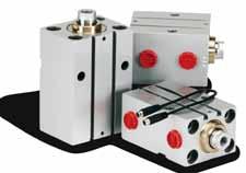
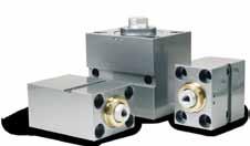
15 Piastre incorporate Incorporated plates CILINDRI IDRAULICI ISO 0/ A TIRANTI TI-RODS ISO 0/ DRAULIC CLINDRS Le piastre incorporate possono essere utilizzate per il montaggio di valvole di controllo a quattro vie con superfici di montaggio ISO 0. Il montaggio avviene direttamente sulla testata posteriore del cilindro, in modo da ridurre i volumi d olio tra la valvola e il cilindro e ottenere una migliore precisione di controllo. Le piastre incorporate sono disponibili con differenti dimensioni e configurazioni delle porte e differenti modalità di fissaggio. The incorporated plates can be used to mount four port control valves with ISO 0 mounting surface. So, the valve can be mounted directly on the rear head of the cylinder, reducing the volume of oil between the valve and the cylinder and obtaining a better control precision. The incorporated plates are available with different oil port dimensions and configurations and different mounting options. PIASTR INCORPORAT: Fissaggio con quattro viti / Incorporated plates: Mounted with four screws Dimensione delle porte / Oil port dimension Disponibile per alesaggi compresi tra Available for bore included between ISO 0-0 N6 0-5 ISO 0-05 N0-00 Collegamenti Link Porta A lato posteriore / Port A Rear side Porta B lato posteriore / Port B Rear side BV-A BV-B BV5-A BV5-B bv-a 75 bv5-a /8 B /8 P T /8 / / T P / bv-b 75 bv5-b 0 /8 A /8 T P /8 PIASTR INCORPORAT: Fissaggio con nipplo conico filettato / Incorporated plates: Mounted with conic threaded niple Disponibile per alesaggi compresi tra Available for bore included between Dimensione delle porte / Oil port dimension ISO 0-0 N ISO 0-05 N Collegamenti Link Porta B lato posteriore / Port B Rear side BA BA5 Ba 75 Ba5 5 B 0 75 / A / P T / 0 75 /8 A /8 T P /8 / A / P T / 0 - Copyright PSSTM Aggiornamenti su / updates on
16 CILINDRI IDRAULICI ISO 0/ A TIRANTI TI-RODS ISO 0/ DRAULIC CLINDRS SNSORI DI PROSSIMITà PROXIMIT SWITCS I sensori di prossimità possono essere utilizzati per il rilevamento della posizione del pistone in corrispondenza dell avvenuto posizionamento vicino alla fine corsa del cilindro. Sono montati sulla testata del cilindro, solitamente in posizione. Il funzionamento dei sensori è possibile solo in cilindri con alesaggi compresi tra 0 e 00 mm dotati di freni. Infatti il sensore genera un campo magnetico ed è in grado di rilevarne la variazione che deriva dall avvicinamento della boccola freno. Il segnale di uscita è regolato da un contatto normalmente aperto. Proximity switches can be used to detect the piston position when it is close to stroke end. They are mounted on the cylinder head, usually in position. The proximity switches works only in cylinders with bore between 0 and 00 mm with cushioning. In facts, the proximity switch generate a magnetic field and it is able to detect its modification due to the proximity of the cushioning bushing. The output signal is modulated by a normally open switch. SNSORI DI PROSSIMITà / PROXIMIT SWITCS DB DB BW BK BL Alesaggio Bore (mm) DB max (mm) Caratteristiche tecniche / Specifications Temperatura d esercizio / Working temperature Pressione massima / Maximum pressure rado di protezione / Protection grade Connettore / Connection Isteresi / ysteresis Ripetibilità / Reapeatability Cablaggio / Wiring Contatto / Switching function Segnale d uscita / Output signal Tensione nominale operativa / Rated operational voltage Corrente nominale operativa / Rated operationale current Tensione di alimentazione / Supply voltage -5 C + C 0 bar IP68 S <= 5% <= 5% fili / wires Normalmente aperto / Normally open PNP DCV 00 ma 0 0 DCV CODICI DI ORDINAZION / ordering codes Sensore anteriore / Front sensor Sensore posteriore / Rear sensor Sensore anteriore e posteriore / Front and rear sensor SPV SPZ SPK Aggiornamenti su / updates on Copyright PSSTM
17 SNSORI MANTICI MANTIC SWITCS CILINDRI IDRAULICI ISO 0/ A TIRANTI TI-RODS ISO 0/ DRAULIC CLINDRS sr sh CBC SMN BW = marrone / brown BL = blu / blue BW BK BL BW = marrone / brown BL = blu / blue BK = nero / black BW BL +/~ /~ Carico Load Caratteristiche tecniche / Specifications Tensione / Voltage Max corrente / Max current (a 5 C) Circuito elettrico / lectric circuit Tempo di inserzione / Switching-on time Tempo di disenserzione / Switching-off time Vita elettrica / lectric lifespan rado di protezione / Protection class Temperatura ambiente / Temperature range Segnalazione / Indicating Cavo / Cable Lunghezza cavo / Cable length Caratteristiche tecniche / Specifications Tensione / Voltage Max corrente / Max current (a 5 C) Circuito elettrico / lectric circuit Tempo di inserzione / Switching-on time Tempo di disenserzione / Switching-off time Vita elettrica / lectric lifespan rado di protezione / Protection class Temperatura ambiente / Temperature range Segnalazione / Indicating Cavo / Cable Lunghezza cavo / Cable length -0 V AC/DC 0. A RD 0.8 ms 0. ms 0 7 impulsi / pulse IP 67 N C LD x 0.5 mm 5.0 m V DC 0.5 A PNP 0.8 ms 0. ms 0 7 impulsi / pulse IP 67 N C LD x0.5 mm 5.0 m STAFFe per sensori magnetici / bracket for magnetic proximity switches Alesaggio / Bore X Staffa / Bracket STA STB STc 5 95 STd codice ordinazione sensore + staffa / Switch + bracket ordering code SR STA Tipo Type RD PNP Sensore Switch SR S Staffa / Bracket STA STB STC STD Per cilindri di alesaggio / For cylinder with bore 5,, 0, 6, Copyright PSSTM Aggiornamenti su / updates on 5
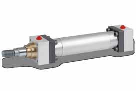
18 CILINDRI IDRAULICI ISO 0/ CON CONTROFLAN COUNTR FLANS ISO 0/ DRAULIC CLINDRS CARATTRISTIC TCNIC TCNICAL CARACTRISTICS Cilindri idraulici con controflange, conformi alla normativa ISO 0/. Possono essere utilizzati con pressioni fino a 0 bar e sono particolarmente adatti in caso di corse molto lunghe. I cilindri con disponibili in molteplici configurazioni di guarnizioni, in base alle condizioni di utilizzo e alle prestazioni desiderate. Tutti i cilindri sono testati prima della consegna in conformità alla normativa ISO 000. ydraulic cylinders with counterflanges, in compliance with the ISO 0/ standard. They can be used with pressures up to 0 bar and they are suitable for long strokes. The cylinders are available in several different sealing configurations, depending on application conditions and desired performances. All the cylinders are tested in compliance with the ISO 000 standard. D/K Caratteristiche tecniche / Specifications Cilindri a norma Standard cylinders ISO 0/ - DIN 5 con controflange / with counter flanges Alesaggi da a 00 Bore mm D da 5 a 00 from to 00 from 5 to 00 K Pressione nominale Pressure bar operating 0 Corsa massima Max stroke mm 000 Tolleranza sulla corsa Stroke tolerance 0 + mm Norma ISO 8 ISO 8 Standard Fluido Fluid Viscosità Viscosity Olio idraulico minerale / ydraulic mineral oil steri fosforici / Phosphoric esters Acqua glicole / FC-fluid... mm /S Codice guarnizione Seal code Alta tenuta igh sealing Basso attrito Low friction Prestazioni Performance Velocità max Max speed Min Temp C Max Olio idraulico ydraulic oil Fluido Fluid steri fosforici Phosphoric esters Acqua glicole FC-fluid S 0,5 m/s L m/s m/s ,5 m/s Aggiornamenti su / updates on Copyright PSSTM
19 CARATTRISTIC TCNIC TCNICAL CARACTRISTICS CILINDRI IDRAULICI ISO 0/ CON CONTROFLAN COUNTR FLANS ISO 0/ DRAULIC CLINDRS D CILINDRO / CLINDR K CILINDRO / CLINDR Componente / Component Componente / Component Flangia chiusura / Closing flange Boccola di guida / uide bushing Testata anteriore / Front head Spillo regolazione frenatura + sfiato /Cushioning adjusting + air bleed Controflangia / Counter flange Viti di chiusura / Closing screw Stelo / Piston rod Canna / Cylinder body Freno anteriore / Front cushioning Pistone / Piston Dado autobloccante stelo / Rod self-locking nut Freno posteriore / Rear cushioning Testata posteriore / Rear head Materiale / Material Materiale / Material Spec. Bronzo / Bronze Acciaio cromato / Chromeplated steel Acciaio temprato / ardened steel Acciaio temprato / ardened steel Specifiche / Specifications Brunito / Burnished Brunito / Burnished Brunito / Burnished Brunito / Burnished Cr 5 µm ISO f7 - Ra 0.0 µm Levigato / oned 8 - Ra 0.0 µm Brunito / Burnished Componente / Component Cava / roove Materiale / Material S L Raschiatore stelo / Rod wiper NBR + PTF NBR + PTF Viton + PTF NBR + PTF C 5 uarnizione stelo / Rod seal ISO 75/ NBR + PTF NBR + PTF Viton + PTF NBR + PTF C 6 uarnizione stelo / Rod seal ISO 75/ PU NBR + PTF Viton + PTF NBR + PTF C 7 uarnizione testata-boccola / ead-bushing sealing NBR + PTF NBR + PTF Viton + PTF NBR + PTF C 8 uarnizione OR canna / OR tube seal NBR NBR Viton NBR 9 uarnizione OR pistone / OR piston seal NBR NBR Viton NBR 0 uarnizione pistone / Piston seal ISO 75/ NBR + PU NBR + PTF Viton + PTF NBR + PTF C uida pistone / Piston guide Resina Resin Resina Resin Resina Resin Resina Resin 0 - Copyright PSSTM Aggiornamenti su / updates on 7
20 CILINDRI IDRAULICI ISO 0/ CON CONTROFLAN COUNTR FLANS ISO 0/ DRAULIC CLINDRS ANCORAI MOUNTIN fori filettati frontali / front threaded holes x ISO MX5 W F RT ØXB B AA WF FLANIA ANTRIOR / Front Flange A ISO M5 F FB ØRD UO TO WF A R flangia Posteriore / Rear FLange b ISO M6 FB UO TO JA R Piedini / Feet e ISO Ms DK CD KC W CO A KL KC CO WF XS KL KL SS+ JA ST ØSB TS US L La controflangia sporge rispetto alla base del piedino (vedi quota KL) The counterflange stick out from of the feet base (see KL dimension). Cerniera con snodo / Ball Jointed D ISO MP5 MS P X XO+ LT CX 8 Aggiornamenti su / updates on Copyright PSSTM

21 ANCORAI MOUNTIN CILINDRI IDRAULICI ISO 0/ CON CONTROFLAN COUNTR FLANS ISO 0/ DRAULIC CLINDRS Cerniera MASCIO / male Clevis C ISO MP MR W L CD XC+ Cerniera Femmina / female Clevis m ISO MP CD MR CB L CF XC+ Perni Anteriori / Front Trunnions g ISO MT ØTD X TC UT PRNI POSTRIORI / RAR TRUNNIONs l ISO MT ØTD TC UT XJ+ ZL+ fori filettati posteriori / rear threaded holes T ISO MX6 RT AA B 0 - Copyright PSSTM Aggiornamenti su / updates on 9
22 CILINDRI IDRAULICI ISO 0/ CON CONTROFLAN COUNTR FLANS ISO 0/ DRAULIC CLINDRS ANCORAI DOPPIO STLO DOUBL ROD MOUNTINS fori filettati frontali / front threaded holes x W F RT ØXB B AA WF ZM++ W+ FLANIA ANTRIOR / front FLAN A FB ØRD UO TO WF A ZM++ W+ R Piedini / Feet e W A A ST KC L CO WF XS KL KL SS+ ZM++ WF+ ØSB TS US La controflangia sporge rispetto alla base del piedino (vedi quota KL) The counterflange stick out from of the feet base (see KL dimension). PernI anteriori / Front Trunnions g ØTD X W+ TC ZM++ UT 0 Aggiornamenti su / updates on Copyright PSSTM
23 DIMNSIONI DIMNSION CILINDRI IDRAULICI ISO 0/ CON CONTROFLAN COUNTR FLANS ISO 0/ DRAULIC CLINDRS Alesaggio Bore Stelo Rod B f9 AA BB BD B CB CD 9 CF CO 8 CX DD P W h X F FB A F JA KC KL L L h0 LT MR max MS max PJ R RD f8 RT SB SS ST TC TD f8 TM TO TS UM UO US UT UW WF W XB f9 XC X XJ XO XS XV min XV max ZJ ZL ZM Mx.5 75 / (*) 5 7 M (*) (*) Mx.5 / (*) (**) M (*) (*) M6x.5 5 / (*) 8 05 (**) M (*) (*) M6x.5 0 / (*) 97 5 (**) M (*) (*) (*) Non conforme a ISO 0/ Does not comply with ISO 0/ standard (**) Quota RD unificata, con riferimento allo stelo maggiore rispetto a quelli previsti dalla norma ISO 0/ RD dimension is unified, with reference to the higher diameter between the ones defined by ISO 0/ standard (*) Mx (**) M (*) (*) M7x (**) M (*) M0x / (**) M (*) = sommare la corsa / add the stroke ++ = sommare il doppio della corsa / add the double of the stroke 0 - Copyright PSSTM Aggiornamenti su / updates on
24 CILINDRI IDRAULICI ISO 0/ CON CONTROFLAN COUNTR FLANS ISO 0/ DRAULIC CLINDRS STRMITà STLO ROD ND standard SF ST Reference point Reference point Reference point Stelo / Rod A B f9 C KK KF M N O P 9 M6x.5 M6x M0x.5 M0x M7x M7x Mx Mx Mx Mx M8x M8x M6x M6x Mx Mx M00x M00x 6 sl din 5 Reference point Alesaggio Bore Stelo Rod A B f9 C KK 9 0 M6x M0x M7x Mx Mx M8x M6x 7 Aggiornamenti su / updates on Copyright PSSTM
25 CODIC DI ORDINAZION ORDRIN COD CODIC ORDINAZION / ORDRIN COD I campi in cui sono stati inseriti i valori di esempio sono obbligatori. / 8 / The fields containing sample values are compulsory. D A 0 CILINDRI IDRAULICI ISO 0/ CON CONTROFLAN COUNTR FLANS ISO 0/ DRAULIC CLINDRS S Serie / Type Alesaggio / Bore Standard D K secuzione speciale / Special version () SX D K Alesaggio / Bore Stelo / Rod SV SZ SK Opzioni/secuzioni speciali Special options/versions (vedi pag. ) (see page ) Sfiato aria / Air bleed Nessuno sfiato / No air bleed Anteriore / Front only Posteriore / Rear only Anteriore + posteriore / Front and rear stremità stelo / Rod extremities (vedi pag. / see page ) S L SF ST SL Filetto maschio (standard) Male thread Filetto femmina Female thread Testa a martello Floating joint Filetto maschio DIN 5 Male thread DIN 5 uarnizioni / Seals (vedi pag. 6 / see page 6) Standard (olio minerale) Standard (mineral oil) Basso attrito / Low friction Viton (alte temperature, esteri fosforici) Viton (high temperature, phosphoric esters) Acqua glicole / FC-fluid ventuale stelo / Possible nd rod Vedi pagg. 8-0 / See pages 8-0 Fori filettati frontali Front tapped holes ISO 0/ MX5 DIN5 Ancoraggio Mounting X Distanziale Spacer SJ SJ 00 SJ SJ 00 Consigliato per corse: Recommended for stroke: da 0 a 000 / from 0 to 000 da 000 a 0 / from 000 to 0 da 0 a 000 / from 0 to 000 da 000 a 000 / from 000 to 000 oltre 000 / above 000 Flangia anteriore Front flange Flangia posteriore Rear flange M5 M6 M5 M6 A B Corsa / Stroke Indicare in mm / Specify in mm Piedini Feet Cerniera con snodo Ball jointed eye Cerniera maschio Male clevis MS MP5 MP MS MP5 D C Frenatura regolabile / Adjustable cushioning () Senza frenatura / Not cushioned V Z Anteriore / Front only Posteriore / Rear only Cerniera femmina Female clevis MP M K Anteriore + posteriore / Front and rear Perni anteriori Front trunnions Perni posteriori Rear trunnions Fori filettati posteriori Rear threaded holes MT MT MX6 L T () Indicare SX ogni qual volta il cilindro ha opzioni o esecuzioni speciali. Indicare poi nell apposita casella, a fine codice, il corrispondente codice (vedi pag. ) seguito da eventuale n. di disegno. Indicate SX when the cylinder has special options or versions. Then, indicate in the appropriate box, after the ordering code, the corresponding code (see page ) followed by the drawing s number, if any. () Per alesaggio 5, la frenatura non è regolabile. For bore 5, the cushioning is not adjustable. 0 - Copyright PSSTM Aggiornamenti su / updates on
26 CILINDRI IDRAULICI ISO 0/ CON CONTROFLAN COUNTR FLANS ISO 0/ DRAULIC CLINDRS opzioni SNSORI DI PROSSIMITà OPTIONS and PROXIMIT SWITCS Orientamento connessioni / Port Location ISO 79- (AS) SA 000 Alesaggio Bore Anteriore Front / / /8 / / / / / Standard Posteriore Rear / / /8 / / / / / Maggiorate / Oversize Anteriore Posteriore Front Rear /8 /8 / / / / / / / / / Anteriore Front / / / Standard Posteriore Rear / / / Maggiorate / Oversize Anteriore Posteriore Front Rear / / / / / / La configurazione standard prevede la porta dell olio in posizione ed eventuali grani di regolazione della frenatura o sfiati sul lato, ad eccezione dell ancoraggio in cui sono in posizione. The standard configuration has the oil ports in position and the cushioning adjustment or air bleed in position, except for the mounting type, where they are in position. BL Per applicazioni speciali in cui è richiesta alta tenuta e alta scorrevolezza (ad esempio, applicazioni con circuiti chiusi), è possibile utilizzare una versione speciale del pistone appositamente modificata. Consultare il nostro ufficio tecnico per verificare l applicabilità di questa soluzione. For special application, where high sealing and low friction is required (i.e., closed circuit application), a special piston is available. Contact our technical department in order to verify the feasibility of this solution. opzioni stelo / ROD ND RRX RRB RRK RR Stelo INOX cromato / Stainless steel chromeplated rod Stelo bonificato cromato / ardened and tempered chromeplated rod Stelo Nikrom / Nikrom rod Stelo temprato cromato / ardened chromeplated rod SD drenaggio boccola / bushing drain M5 Il drenaggio della boccola impedisce l accumulo di fluido dietro al raschiatore. Una connessione situata tra il raschiatore e la tenuta a labbro consente il rinvio al serbatoio del fluido. Il drenaggio è normalmente posizionato sul lato opposto alla bocca olio. The bushing drain avoids the accumulation of liquid behind the scraper. A connection between the scraper and the lip seal allows to send the fluid back to the tank. The drain is usually installed on the opposite side of the oil port. SNSORI DI PROSSIMITà / PROXIMIT SWITCS Alesaggio Bore (mm) DB max (mm) DB DB BW BK BL SPV SPZ SPK Sensore anteriore / Front sensor Sensore posteriore / Rear sensor Sensore anteriore e posteriore / Front and rear sensor Per caratteristiche e modalità di funzionamento del sensore fare riferimento alla documentazione a pagina. For proximity switches features, see documentation at page. Aggiornamenti su / updates on Copyright PSSTM
27 Piastre incorporate Incorporated plates CILINDRI IDRAULICI ISO 0/ CON CONTROFLAN COUNTR FLANS ISO 0/ DRAULIC CLINDRS Le piastre incorporate possono essere utilizzate per il montaggio di valvole di controllo a quattro vie con superfici di montaggio ISO 0. Il montaggio avviene direttamente sulla testata posteriore del cilindro, in modo da ridurre i volumi d olio tra la valvola e il cilindro e ottenere una migliore precisione di controllo. Le piastre incorporate sono disponibili con differenti dimensioni e configurazioni delle porte e differenti modalità di fissaggio. The incorporated plates can be used to mount four port control valves with ISO 0 mounting surface. So, the valve can be mounted directly on the rear head of the cylinder, reducing the volume of oil between the valve and the cylinder and obtaining a better control precision. The incorporated plates are available with different oil port dimensions and configurations and different mounting options. PIASTR INCORPORAT: Fissaggio con quattro viti / Incorporated plates: Mounted with four screws Dimensione delle porte / Oil port dimension Disponibile per alesaggi Available for bore ISO 0-0 N6 0-5 ISO 0-05 N0-00 Collegamenti Link Porta A lato posteriore / Port A Rear side Porta B lato posteriore / Port B Rear side BV-A BV-B BV5-A BV5-B bv-a 75 bv5-a /8 B /8 P T /8 / / T P / bv-b 75 bv5-b 0 /8 A /8 T P /8 PIASTR INCORPORAT: Fissaggio con nipplo conico filettato / Incorporated plates: Mounted with conic threaded niple Disponibile per alesaggi Available for bore Dimensione delle porte / Oil port dimension ISO 0-0 N ISO 0-05 N Collegamenti Link Porta B lato posteriore / Port B Rear side BA BA5 Ba 75 Ba5 5 B 0 75 / A / P T / 0 75 /8 A /8 T P /8 / A / P T / 0 - Copyright PSSTM Aggiornamenti su / updates on 5
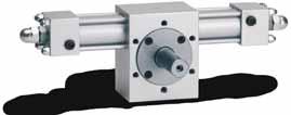
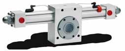
28 SRVOCILINDRI IDRAULICI ISO 0/ ISO 0/ DRAULIC SRVOCLINDRS CARATTRISTIC TCNIC TCNICAL CARACTRISTICS Versione con trasduttore esterno. Per ancoraggi X, A,,,, L, R Version with external transducer. For mountings X, A,,,, L, R Versione con trasduttore interno. Per ancoraggi B, D, C, M, Q, S, T. Consultare il nostro ufficio tecnico. Version with internal transducer. For mountings B, D, C, M, Q, S, T. Contact our technical department. I servocilindri ISO 0/ sono disponibili sia a tiranti (versione TD e TK), sia con controflange (versione T e TX). I servocilindri sono predisposti con un trasduttore elettronico che permette di conoscere la posizione assoluta dello stelo. La scelta del tipo di trasduttore è in funzione delle prestazioni che si vogliono ottenere. La precisione di posizionamento è determinata da elementi: la risoluzione del trasduttore e il sistema di comando del cilindro. I trasduttori sono previsti di tipologie: TMPOSONIC Consente alte risoluzioni e vari tipi di controllo; può coprire tutte le lunghezze di corsa necessarie. POTNZIOMTRICO Il segnale di uscita è dato da un cursore che scorre su una pista potenziometrica. La tensione è proporzionale alla posizione del cursore. La corsa massima possibile è di 0 mm. INDUTTIVO Fornisce un segnale in tensione o in corrente, generato da un circuito elettronico separato. La corsa massima possibile è di 000 mm. The ISO 0/ servocylinders are available both with tie rods (TD and TK versions) and with counter flanges (T and TX version). The servocylinders include an electronic transducer, which allows to obtain the absolute position of the rod. The type of transducer to be used depends on the performance you need. The precision of positioning is determined by elements: the resolution of the transducer and the drive system of the cylinder. type of transducers are available: TMPOSONIC: it allows high resolutions and different types of control; it supports all the stroke lengths necessary. potentiometric: the output signal is given from a cursor sliding on a piezoelectric. The maximum stroke allowed is 0 mm. INDUCTIV: it emits a voltage or current signal generated by a separated electrical circuit. The maximum stroke allowed is 000 mm. MV MA MS PV IV IA Tipo trasduttore / Transducer type Temposonic Temposonic Temposonic Potenziometrico / Potentiometric Induttivo / Inductive Induttivo / Inductive Alimentazione / Supply voltage V DC V DC V DC Max V V DC V DC Uscita / Output 0-0 V -0 ma SSI (Syncronic Serial Interface) 0-0 V -0 ma Risoluzione / Resolution Infinita / ndless Infinita / ndless Infinita / ndless Infinita / ndless Infinita / ndless Linearità / Linearity < ±0.0% F.S. (min ± µm) < ±0.0% F.S. (min ± µm) < ±0.0% F.S. (min ± µm) ±0.% F.S. ±0.% F.S. ±0.% F.S. Ripetibilità / Repeatability < ±0.00% F.S. (min ±.5 µm) < ±0.00% F.S. (min ±.5 µm) < ±0.00% F.S. (min ±.5 µm) Isteresi / ysteresis < µm < µm < µm Assorbimento / Absorption 00 ma 00 ma 00 ma Velocità max / Max speed m/s m/s m/s m/s m/s m/s Temperatura / Temperature -0 + C -0 + C -0 + C -0 + C -0 + C -0 + C Corsa max / Max stroke F.S. = fondo scala / full scale I servocilindri possono essere equipaggiati con piastre di interfaccia ISO che consentono il montaggio diretto a bordo del cilindro di: - lettrovalvole ON/OFF - lettrovalvole proporzionali - Servovalvole Questa configurazione abbinata a una UNITà DI CONTROLLO assicura una rigidità idraulica ottimale che migliora notevolmente i tempi di risposta, la ripetibilità e la precisione di posizionamento. The servocylinders can be equipped with ISO interface plates, which allow to mount directly on the cylinder the following elements: - Solenoid valves ON/OFF - Proportional solenoid valves - Servovalves This configuration, together with a CONTROL UNIT, ensures an optimal hydraulic rigidity, which drastically increments the answer time, the repeteability and the precision of the positioning. Sfiato aria Per un corretto funzionamento dei servocilindri è indispensabile che, durante la messa in opera, siano perfettamente spurgati dall aria presente nel cilindro. Per questo, questi cilindri, oltre agli spurghi sulle testate, hanno un grano di spurgo in testa allo stelo che consente l evaquazione dell aria presente nella camera che accoglie il trasduttore. La particolare dislocazione di questo spurgo consente l operazione anche quando il cilindro è operativo, senza dover togliere lo stelo dal suo alloggiamento. Air bleed To allow the servocylinders to work correctly, you need to completely exhaust the air within the cylinder when setting them up. Therefore, these cylinders not only include air bleed on the heads, but they also have an air bleed on the head of the rod for exhausting the air within the chamber of the transducer. The particular position of this air bleed allows working even when the cylinder is operative, without having to remove the rod from its housing. 6 Aggiornamenti su / updates on Copyright PSSTM
29 CODIC DI ORDINAZION ORDRIN COD SRVOCILINDRI IDRAULICI ISO 0/ ISO 0/ DRAULIC SRVOCLINDRS I campi in cui sono stati inseriti i valori di esempio sono obbligatori. The fields containing sample values are compulsory. codice ordinazione / ordering code TD MA / / A 0 L Serie / Type a tiranti tie rods controflange counterflanges Trasduttore / Transducer MV Temposonic MA MS Potenziometrico / Potentiometric PV IV Induttivo / Inductive ia IA secuzione speciale / Special version () SX TD TK T TX Alesaggio / Bore TD TK T TX Alesaggio / Bore ventuale stelo / Possible nd rod Stelo / Rod L SV SZ SK Distanziale Spacer SJ SJ 00 SJ SJ 00 Opzioni/secuzioni speciali Special options/versions Sfiato aria / Air bleed uarnizioni / Seals (vedi pag. / see page ) Basso attrito / Low friction Viton (alte temperature, esteri fosforici) Viton (high temperature, phosphoric esters) Acqua glicole / FC-fluid Consigliato per corse: Recommended for stroke: da 0 a 000 / from 0 to 000 da 000 a 0 / from 000 to 0 da 0 a 000 / from 0 to 000 da 000 a 000 / from 000 to 000 oltre 000 / above 000 Consultare il nostro ufficio tecnico / Contact our technical department Corsa / Stroke Indicare in mm / Specify in mm (vedi pag. ) (see page ) stremità stelo / Rod extremities (vedi pag. 0 / see page 0) SF ST SL Nessuno sfiato / No air bleed Anteriore / Front only Posteriore / Rear only Anteriore + posteriore / Front and rear Filetto maschio (standard) Male thread Filetto femmina Female thread Testa a martello Floating joint Filetto maschio DIN 5 Male thread DIN 5 TD TK T TX Vedi pagg. 6-8 / See pages 6-8 Cilindro base Front tapped holes Flangia anteriore Front flange Piedini Feet Perni anteriori Front trunnions Perni intermedi Intermediate trunnions Perni posteriori Rear trunnions () ISO 0/ MX5 M5 MS MT MT MT DIN5 M5 MS MT Ancoraggio Mounting X A L () Indicare SX ogni qual volta il cilindro ha opzioni o esecuzioni speciali. Indicare poi nell apposita casella, a fine codice, il corrispondente codice (vedi pag. ) seguito da eventuale n. di disegno. Indicate SX when the cylinder has special options or versions. Then, indicate in the appropriate box, after the ordering code, the corresponding code (see page ) followed by the drawing s number, if any. () Per ancoraggio (MT), indicare in coda al codice la dicitura XV seguita dal valore della quota XV (vedi pagg. 7-8). For mounting (MT), indicate at the end of the code the letters XV followed by the XV quote value (see pages 7-8). Tiranti prolungati anteriori xtended front tie-rods MX R Flangia posteriore Rear flange M6 M6 B Cerniera con snodo Ball jointed eye Cerniera maschio Male clevis Cerniera femmina Female clevis Tiranti prolungati ant. e post. xtended front and rear tie-rods Tiranti prolungati posteriori xtended rear tie-rods MP5 MP MP MX MX MP5 D C M Q S Consultare il nostro ufficio tecnico Contact our technical department Fissaggio posteriore Rear tapped holes MX6 T 0 - Copyright PSSTM Aggiornamenti su / updates on 7
30 P SSTM si riserva la possibilità di modificare i prodotti rispetto a quanto illustrato nel presente catalogo. P SSTM reserves the possibility to change the products from what illustrated in this catalogue. Tutto il materiale del presente catalogo non può essere utilizzato senza consenso scritto della P SSTM. All the content of this catalogue must not be used without explicit written authorization by P SSTM. 0 - Copyright PSSTM Aggiornamenti su / updates on
31 P SSTM srl a socio unico Sede Amm.-Mag.: Via N.Tintorri, 5/B 086 Concorezzo MB Tel Fax vendite@hpsystem-srl.it
cilindri oleodinamici hydraulic cylinders catalogo tecnico technical catalog
 cilindri oleodinamici hydraulic cylinders catalogo tecnico technical catalog Aggiornamenti su / updates on www.hpsystem-srl.it 2014 - Copyright HPSYSTEM servocilindri IDRAULICI ISO 6022 ISO 6022 HYDRAULIC
CILINDRI IDRAULICI ISO ISO HYDRAULIC CYLINDERS
 CILINDRI IDRAULICI ISO ISO HYDRAULIC CYLINDERS hydraut.com 2 hydraut.com CILINDRI IDRAULICI ISO 6020/2 ISO 6020/2 HYDRAULIC CYLINDERS CILINDRI IDRAULICI ISO 6020/2 A TIRANTI TIE-RODS ISO 6020/2 HYDRAULIC
CILINDRI IDRAULICI ISO 6022 ISO 6022 HYDRAULIC CYLINDERS
 CARATTERISTICHE TECNICHE [ TECHNICAL CHARACTERISTICS ] CILINDRI IDRAULICI ISO 22 ISO 22 HYDRAULIC CYLINDERS CARATTERISTICHE TECNICHE / SPECIFICATIONS Cilindri a norma Standard cylinders Alesaggi mm ISO
ATTUATORI ROTANTI ROTARY ACTUATORS CARATTERISTICHE TECNICHE TECHNICAL CHARACTERISTICS CODICE DI ORDINAZIONE ORDERING CODE 54-56
 ATTUATORI ROTANTI CARATTERISTICHE TECNICHE CODICE DI ORDINAZIONE ORDERING CODE -6 3 ATTUATORI ROTANTI CARATTERISTICHE TECNICHE Gli attuatori rotanti generano una coppia attraverso una ruota dentata e una
ISO 6020/2 HYDRAULIC CYLINDERS
 CARATTERISTICHE TECNICHE [ TECHNICAL CHARACTERISTICS ] CILINDRI IDRAULICI ISO /2 ISO /2 HYDRAULIC CYLINDERS CD/DK STANDARD / STANDARD CARATTERISTICHE TECNICHE / SPECIFICATIONS Cilindri a norma Standard
Alesaggi. Pressione. Fluido Fluid Viscosità Viscosity. Alesaggi. Viscosità Viscosity. Prestazioni Performance. Velocità max Max speed. Temp C.
 CILINDRI IDRAULICI ISO 0/2 A TIRANTI TI-RODS ISO 0/2 DRAULIC CLINDRS CARATTRISTIC TCNIC TCNICAL CARACTRISTICS Cilindri idraulici a tiranti, conformi alla normativa ISO 0/2, anche per uso con sensori magnetici.
cilindri oleodinamici hydraulic cylinders catalogo tecnico technical catalog
 cilindri oleodinamici hydraulic cylinders catalogo tecnico technical catalog ggiornamenti su / updates on www.hpsystem-srl.it 014 - Copyright HPSSTEM -1 CILINDRI IDRULICI ISO 60 ISO 60 HDRULIC CLINDERS
CILINDRI IDRAULICI ISO
 -1 CILINDRI IDRULICI ISO 60 ISO 60 HDRULIC CLINDERS CRTTERISTICHE TECNICHE TECHNICL CHRCTERISTICS NCORGGI MOUNTING DIMENSIONI DIMENSION opzioni ed esecuzioni speciali options and special executions codice
CILINDRI IDRAULICI ISO 6022 ISO 6022 HYDRAULIC CYLINDERS
 -1 CILINDRI IDRULICI ISO 60 ISO 60 HDRULIC CLINDERS CRTTERISTICHE TECNICHE TECHNICL CHRCTERISTICS NCORGGI MOUNTING DIMENSIONI DIMENSION OPZIONI ED ESECUZIONI SPECILI OPTIONS ND SPECIL EXECUTIONS CODICE
CILINDRI IDRAULICI ISO 6022 ISO 6022 HYDRAULIC CYLINDERS
 CILINDRI IDRULICI ISO ISO HDRULIC CLINDERS CRTTERISTICHE TECNICHE TECHNICL CHRCTERISTICS Cilindri idraulici per impieghi gravosi, conformi alla normativa ISO. I cilindri sono disponibili in vari ancoraggi
CILINDRI IDRAULICI ISO 6022 ISO 6022 HYDRAULIC CYLINDERS
 CILINDRI IDRULICI ISO ISO HDRULIC CLINDERS CRTTERISTICHE TECNICHE TECHNICL CHRCTERISTICS Cilindri idraulici per impieghi gravosi, conformi alla normativa ISO. I cilindri sono disponibili in vari ancoraggi
CILINDRI OLEODINAMICI - serie ISO 6020/2 Cilindri a tiranti con pressione di lavoro fino a 210 bar
 CILINDRI OLEODINAMICI - serie ISO 6020/2 Cilindri a tiranti con pressione di lavoro fino a 210 bar 1 INDICE CILINDRI 6020/2 CARATTERISTICHE TECNICHE pag. 3-8 o PRESSIONE DI UTILIZZO pag. 3 o FISSAGGI pag.
SERIE CILINDRI INOX ISO ISO STAINLESS STEEL CYLINDERS
 CILINDRI INOX ISO 15552 ISO 15552 STAINLESS STEEL CLINDERS CARATTERISTICHE TECNICHE - TECHNICAL CHARACTERISTICS Pressione di esercizio Working pressure Temperatura di esercizio Working temperature 1 10
CILINDRI IDRAULICI ISO 6020/2 con controflange SERVOCILINDRI ISO 6020/2 ISO 6020/2 SERVOCYLINDERS
 www.confortinet.com CILINDRI IDRULICI ISO / a tiranti tie-rods ISO / DRULIC CLINDRS CILINDRI IDRULICI ISO / con controflange COUNTR FLNGS ISO / DRULIC CLINDRS SRVOCILINDRI ISO / ISO / SRVOCLINDRS - 6-6-
CILINDRI IDRAULICI ISO 6020/2 con controflange. tie-rods ISO 6020/2 HYDRAULIC CYLINDERS COUNTER FLANGES ISO 6020/2 HYDRAULIC CYLINDERS
 CILINDRI IDRULICI ISO / a tiranti tie-rods ISO / DRULIC CLINDRS CILINDRI IDRULICI ISO / con controflange COUNTR FLNGS ISO / DRULIC CLINDRS SRVOCILINDRI ISO / ISO / SRVOCLINDRS - 6-6- CILINDRI IDRULICI
CILINDRI OLEODINAMICI - serie ISO 6020/2 Cilindri a tiranti con pressione di lavoro fino a 210 bar
 CILINDRI OLEODINAMICI - serie ISO 6020/2 Cilindri a tiranti con pressione di lavoro fino a 210 bar INDICE CILINDRI 6020/2 CARATTERIICHE TECNICHE pag. 2- o PRESSIONE DI UTILIZZO pag. 2 o FISSAGGI pag. 3
CILINDRI IDRAULICI ISO 6020/2 con controflange SERVOCILINDRI ISO 6020/2 ISO 6020/2 SERVOCYLINDERS
 www.confortinet.com CILINDRI IDRULICI ISO / a tiranti tie-rods ISO / DRULIC CLINDRS CILINDRI IDRULICI ISO / con controflange COUNTR FLNGS ISO / DRULIC CLINDRS SRVOCILINDRI ISO / ISO / SRVOCLINDRS - 6-6-
CIS: STANDARD ISO 6020/ DIN A tirante Esercizio 160 Standard 0.5 Standard C. 3000mm mm norma ISO 8131
 A-a-3 CARATTERISTICHE Cilindro a norma Pressione bar Massima velocità m/s Temperatura fluido Corsa massima mm Tolleranza sulla corsa Fluido Viscosita : STANDARD ISO 6020/2 1991 DIN 4 A tirante Esercizio
HD/HK CILINDRI IDRAULICI ISO 6020/2 CON CONTROFLANGE COUNTER FLANGES ISO 6020/2 HYDRAULIC CYLINDERS
 CIINDRI IDRUICI ISO 60/ CON CONROFN COUNR FNS ISO 60/ DRUIC CINDRS CRRISIC CNIC CNIC CRCRISICS Cilindri idraulici con controflange, conformi alla normativa ISO 60/. Possono essere utilizzati con pressioni
Serie X. Caratteristiche Tecniche / Technical Characteristics. Materiali e Componenti / Component Parts and Materials
 Caratteristiche Tecniche / Technical Characteristics Materiali e Componenti / Component Parts and Materials Asta pistone acciaio C40 Cromato Chrome steel C40 piston rod Dado in acciaio zincato Zinc-plated
SERIE CILINDRI INOX ISO ISO STAINLESS STEEL CYLINDERS
 SRI CILINDRI INOX ISO 15552 ISO 15552 STAINLSS STL CLINDRS CARATTRISTICH TCNICH - TCHNICAL CHARACTRISTICS Pressione di esercizio Working pressure Temperatura di esercizio Working temperature 1 10 bar 0
cilindri corsa breve short stroke cylinders
 Dimensioni di ingombro ridotte Reduced external dimensions Grande affidabilità e lunga durata High reliability and long life time Versione magnetica standard Standard magnetic version Esecuzioni e corse
sensori per cilindri magnetic sensors for cylinders
 Schema di collegamento: fili Wiring diagram: wires Modello Model RS1-A RS-A RS5-C RS-A RS-A Funzione Function Reed NC Reed NC Numero fili Number of wires Lunghezza cavo Lenght of wires Connettore Connector
CILINDRI SENZA STELO RODLESS CYLINDERS
 Il cilindro senza stelo nasce dall esigenza di ridurre gli ingombri a parità di corsa E' fornito in diverse versioni e gli alesaggi variano da 25 a 63. I pregi principali di questo cilindro sono l'eccezionale
Minicilindri ISO 6432 Minicylinders ISO 6432
 Dati Tecnici - Technical data Fluido - Fluid Temperatura d'esercizio - Temperature range Pressione d'esercizio - Working pressure range Aria filtrata con o senza lubrificazione - Filtered air with or without
CILINDRI COMPATTI GUIDATI - SERIE 6 GUIDE COMPACT CYLINDERS - 6 SERIES
 Il nuovissimo cilindro compatto guidato prodotto da AIRWORK, è un attuatore lineare con caratteristiche di grande robustezza e minimi ingombri, infatti è dotato di un cilindro pneumatico centrale con un
CILINDRI OLEODINAMICI - serie CTO Cilindri a tiranti con pressione di lavoro fino a 160 bar
 CILINDRI OLEODINAMICI - serie CTO Cilindri a tiranti con pressione di lavoro fino a 160 bar 1 INDICE CILINDRI CTO CARATTERISTICHE TECNICHE pag. 3-6 o PRESSIONE DI UTILIZZO pag. 3 o FISSAGGI pag. 4 o FRENATURA
CILINDRI IDRAULICI ISO 6020/2 a tiranti tie-rods ISO 6020/2 HYDRAULIC CYLINDERS
 - CIINDRI IDRUICI ISO 0/ a tiranti tie-rods ISO 0/ DRUIC CINDRS CRRISIC CNIC CNIC CRCRISICS NCORI MOUNIN DIMNSIONI DIMNSION SRMIà SO ROD ND codic di ordinazione ordering code opzioni OIONS iastre incorporate
CILINDRI IDRAULICI ISO 6020/2 A TIRANTI TIE-RODS ISO 6020/2 HYDRAULIC CYLINDERS SERVOCILINDRI ISO 6020/2 ISO 6020/2 SERVOCYLINDERS
 ww.confortinet.com CIINDRI IDRUICI ISO / TIRNTI TI-RODS ISO / DRUIC CINDRS CIINDRI IDRUICI ISO / CON CONTROFNG COUNTR FNGS ISO / DRUIC CINDRS SRVOCIINDRI ISO / ISO / SRVOCINDRS - 6-6- CIINDRI IDRUICI
CILINDRI ISO INOX CYLINDERS ISO STAINLESS STEEL
 Serie di cilindri completamente in acciaio inox. Ideali per ambienti nel settore alimentare, vengono realizzati in tre diametri 16-20-25. Anche in questa versione le testate sono fissate alla camicia mediante
CILINDRI OLEODINAMICI - serie C T I
 CILINDRI OLEODINAMICI - serie C T I INDICE CILINDRI 6020/2 CARATTERIICHE TECNICHE pag. 2-7 o PRESSIONE DI UTILIZZO pag. 2 o FISSAGGI pag. 3 o FRENATURA pag. 5 o DIANZIE pag. 5 o GUARNIZIONI pag. 6 o EREMITÁ
Cilindri compatti Compact cylinders SERIE 380
 Cilindri compatti SERIE 380 ed. 20 7 SERIE 380 Cilindri compatti CARATTERISTICHE TECNICHE alesaggi...-32 40 50 63 80 0 versioni...-doppio effetto -doppio effetto antirotante -semplice effetto stelo retratto
sensori per cilindri magnetic sensors for cylinders Schema di collegamento: 2 fili Wiring diagram: 2 wires RS2-A RS1-A RS3-A RS4-A RS5-C Modello Model
 Schema di collegamento: fili Wiring diagram: wires Modello Model RS1-A RS-A RS5-C RS-A RS4-A Funzione Function Reed NC Reed NC Numero fili Number of wires Lunghezza cavo Length of wires Connettore Connector
M.G. COMPONENTI PNEUMATICA OLEODINAMICA AUTOMAZIONE COSTRUZIONE CILINDRI OLEODINAMICI CILINDRI PNEUMATICI NORMA NFPA - J.I.C.
 M.G. COMPONENTI PNEUMATICA OLEODINAMICA AUTOMAZIONE COSTRUZIONE CILINDRI OLEODINAMICI CILINDRI PNEUMATICI NORMA NFPA - J.I.C. SERIE PNEUMATICA PESANTE 18 BAR Via G. Garibaldi, 38/a 16/b 069 VILLA CARCINA
Serie Cylinders. Serie Mini Inox. Serie CA - CAF. Serie A95 Pag Serie Mini. Serie B. Serie Q. Serie X. Serie NHA. Serie W Pag
 Serie Cylinders Cilindro a Cartuccia Ø6-16 mm Cartridge Cylinders Ø6-16 mm MiniCilindri ISO 6432 Ø 8-25 mm MiniCylinders ISO 6432 Ø 8-25 mm MiniCilindri ISO 6432 Ø 16-25 mm MiniCylinders ISO 6432 Ø 16-25
CILINDRI OLEODINAMICI - serie C T O
 CILINDRI OLEODINAMICI - serie C T O INDICE CARATTERISTICHE TECNICHE pag. 2-5 o PRESSIONE DI UTILIZZO pag. 2 o FISSAGGI pag. 3 o FRENATURA pag. 5 o GUARNIZIONI pag. 5 CODICE DI ORDINAZIONE pag. 6 SEZIONE
TABELLE TECNICHE TECHNICAL TABLES
 TABELLE TECNICHE 59 CILINDRI IDRAULICI ISO 020/2 ISO 020/2 HYDRAULIC CYLINDERS TABELLE TECNICHE VERIFICA DEL CARICO DI PUNTA / BUCKLING VERIFICATION Quando il cilindro lavora in spinta, lo stelo del cilindro
Cilindri corsa breve Short stroke cylinders SERIE 360
 Cilindri corsa breve SERIE 3 ed. SERIE 3 Cilindri corsa breve CARATTERISTICHE TECNICHE alesaggi... 32 versioni... - doppio effetto - semplice effetto stelo retratto - semplice effetto stelo esteso - stelo
SERIE CILINDRI TONDI INOX STAINLESS STEEL ROUND CYLINDERS
 CILINDRI TONDI INOX STAINLESS STL ROUND CYLINDERS CARATTERISTICHE TECNICHE - TECHNICAL CHARACTERISTICS Pressione di esercizio Working pressure Temperatura di esercizio Working temperature Versioni - Versions
COMPANY PROFILE PROFILO AZIENDALE PRODUCTION SYSTEM SISTEMA PRODUTTIVO CONSEGNE RAPIDE FAST DELIVERY
 PROFILO AZIENDALE COMPANY PROFILE Dal 1972, Conforti Oleodinamica è specializzata nella progettazione e produzione di cilindri oleodinamici. Soddisfa con successo i bisogni dei suoi clienti internazionali
CILINDRI ISO SERIE CY CYLINDERS ISO CY SERIES
 - SERIE CY - CY SERIES I cilindri serie CY di Airwork sono realizzati rispettando la normativa ISO 15552 ed hanno alesaggi compresi tra 32 e 125 mm. Doppio effetto, ammortizzati e magnetici sono indicati
CILINDRI PNEUMATICI E ACCESSORI PNEUMATIC CYLINDERS AND ACCESSORIES
 CILINDRI PNEUMATICI E ACCESSORI PNEUMATIC CYLINDERS AND ACCESSORIES EDIZIONE 2017 EDITION 2017 EDIZIONE 2017 EDITION sui cilindri. 27 28 31 32 34 35 MINICILINDRI A NORME ISO 6432 INOX 36 38 40 41 43 44
Cilindri CNOMO Cylinders CNOMO SERIE 310
 Cilindri CNOMO Cylinders CNOMO SERIE 3 ed. 9 SERIE 3 Cilindri CNOMO CARATTERISTICHE TECNICHE A doppio effetto con deceleratori (magnetico su richiesta). alesaggi lunghezza deceleratore 35 35 fissaggi...flangia
SERIE CILINDRI ISO ISO CYLINDERS
 CILINDRI ISO 15552 ISO 15552 CYLINDERS CRTTERISTICHE TECNICHE - TECHNICL CHRCTERISTICS Pressione di esercizio Working pressure Temperatura di esercizio Working temperature 1 10 bar (doppio effetto - double
Anniversario CILINDRI OLEODINAMICI ISO 6020/2 ISO 6020/2 15 IT
 25 Anniversario CILINDRI OLEODINAMICI ISO 6020/2 ISO 6020/2 15 IT INDICE CHI SIAMO GAMMA DEI CILINDRI OLEODINAMICI ISO 6020/2 CARATTERISTICHE GENERALI CARATTERISTICHE TECNICHE SEZIONE CILINDRI COMPOSIZIONE
CILINDRI IDRAULICI ISO 6020/2 A TIRANTI TIE-RODS ISO 6020/2 HYDRAULIC CYLINDERS
 - CIINDRI IDRUICI ISO 0/ IRNI I-RODS ISO 0/ DRUIC CINDRS CRRISIC CNIC CNIC CRCRISICS NCORI MOUNIN DIMNSIONI DIMNSION SRMIÀ SO ROD ND CODIC DI ORDINZION ORDRIN COD OZIONI OIONS ISR INCOROR INCORORD S SNSORI
STAINLESS STEEL DIN ISO CYLINDERS Ø32-125
 CILINDRI DIN ISO 15552 Ø32-125 INOX STINLSS STL DIN ISO 15552 CYLINDRS Ø32-125 Versioni disponibili - vailable versions CD..XF - CDM..XF - CDP..XF - CDMP..XF CD..XF - CDM..XF - CDP..XF - CDMP..XF Informazioni
semplice effetto Alesaggi ø 6, 10, 16 mm e corse 5, 10, 15 mm Con raccordo super-rapido incorporato ø 4 mm o attacco M5
 > Minicilindri compatti Serie 4 CATALOGO > Release 8.7 Minicilindri compatti Serie 4 Semplice effetto Alesaggi ø 6, 0, 6 mm e corse 5, 0, 5 mm Con raccordo super-rapido incorporato ø 4 mm o attacco M5»»
1 10 bar (doppio effetto - double acting)
") CRTTERISTICHE TECNICHE - TECHNICL CHRCTERISTICS Pressione di esercizio Working pressure Temperatura di esercizio Working temperature 1 10 bar (doppio effetto - double acting) 0 +80 C (-20 C con aria secca
CRTTERISTICHE TECNICHE - TECHNICL CHRCTERISTICS Pressione di esercizio Working pressure Temperatura di esercizio Working temperature 1 10 bar (doppio effetto - double acting) 0 +80 C (-20 C con aria secca
NORMA NFPA - J.I.C. LEGGERA OLEODINAMICA 70 BAR PESANTE PNEUMATICA 18 BAR PESANTE OLEODINAMICA 210 BAR
 SERIE NORMA NFPA - J.I.C. LEGGERA OLEODINAMICA 70 BAR PESANTE PNEUMATICA 18 BAR PESANTE OLEODINAMICA 210 BAR Via G. Garibaldi, 38/a 16/b 25069 VILLA CARCINA (Brescia) Telefono 030/8982582 r.a. Fax 030/8982584
KIT COMPONENTI SERIE CH
 KIT 6020/2 KIT COMPONENTI SERIE CH A NORME ISO 6020/2-1991 - DIN 24554 SERIE 160 BAR COMPATTA Grices offre ai propri clienti kit di montaggio per cilindri della serie CH (ISO 6020/2), il semplice processo
M.G. COMPONENTI PNEUMATICA - OLEODINAMICA AUTOMAZIONE COSTRUZIONE CILINDRI OLEODINAMICI
 M.G. COMPONENTI PNEUMATICA - OLEODINAMICA AUTOMAZIONE COSTRUZIONE CILINDRI OLEODINAMICI CILINDRI OLEODINAMICI COMPATTI RETTANGOLARI serie MG-CB Via G. Garibaldi, 38/a - 16/b - 25060 VILLA CARCINA (Brescia)
CILINDRI CNOMO CNOMO CYLINDER
 CILINDRI CNOMO CNOMO CYLINDER CARATTERISTICHE TECNICHE E STANDARD QUALITATIVI OPERATING FEATURES AND QUALITATIVE STANDARDS La norma C.N.O.M.O 06.07.02 sostituita dalla attuale AFNOR NF E 49-001 definisce
Matricola Stocchetta Cilindri
 SL I cilindri standard Stocchetta sono completamente ed accuratamente identificati dalla sigla del modello, che include le specifiche costruttive. Per costruire la sigla di ordinazione di un modello si
CILINDRI TONDI INOX CP95 ø32-63 STAINLESS STEEL CP95 ROUND CYLINDERS ø32-63
 Cilindri tondi ø32-63 ltamente resistenti con testate cianfrinate e interamente realizzati in acciaio inox. Disponibili in versione magnetica o non, con o senza ammortizzo regolabile, doppio effetto, a
Progettazione, Costruzione e Revisione cilindri oleodinamici Hydraulic Cylinder Design, Construction and Revision
 Progettazione, Costruzione e Revisione cilindri oleodinamici Hydraulic Cylinder Design, Construction and Revision Progettazione, Costruzione e Revisione cilindri oleodinamici per settori: Industriale,
CILINDRI STOPPER STOPPER CYLINDERS CILINDRI STOPPER STOPPER CYLINDERS
 CARATTERISTICHE TECNICHE - TECHNICAL CHARACTERISTICS Pressione di esercizio 0 bar (semplice effetto - single acting) Working pressure Temperatura di esercizio Working temperature Versioni - Versions Alesaggi
VALVOLE AD OTTURATORE COMANDO PNEUMATICO
 VALVOLE AD OTTURATORE COMANDO PNEUMATICO Attuatore con Pistone Pneumatico Corpo di Acciaio Inox A316, e Ottone Valvole Coassiali a Spola Comando Pneumatico ed Elettrico Corpo di Acciaio Inox A304 - A316
SERIE MINICILINDRI ISO 6432 ISO 6432 MICRO CYLINDERS
 MINICILINDRI IS 6432 IS 6432 MICR CYLINDERS CARATTERISTIE TECNIE - TENICAL ARACTERISTICS Pressione di esercizio Working pressure Temperatura di esercizio Working temperature Versioni - Versions 1 10 bar
1/ Doppio effetto, ammortizzati, magnetici Ø mm
 CATALOGO > Release 8.6 > Cilindri Serie 40 Cilindri Serie 40 Doppio effetto, ammortizzati, magnetici 60-200 - 250-320 mm»» Conformi alla normativa ISO 5552 e alle precedenti ISO 643 VDMA 24562»» Ammortizzatore
SERIE CILINDRI ISO ISO CYLINDERS
 CILINDRI ISO 15552 ISO 15552 CYLINDERS CARATTERISTICE TECNICE - TECNICAL CARACTERISTICS Pressione di esercizio Working pressure Temperatura di esercizio Working temperature 1 10 bar (doppio effetto - double
1/ Doppio effetto, ammortizzati, magnetici Ø mm
 CATALOGO > Release 8.7 > Cilindri Serie 40 Cilindri Serie 40 Doppio effetto, ammortizzati, magnetici 60-200 - 250-320 mm Conformi alla normativa ISO 5552 e alle precedenti ISO 643 VDMA 24562 Ammortizzatore
Cilindri Serie 40. Doppio effetto, ammortizzati, magnetici ø mm. Conformi alle normative ISO 6431/VDMA 24562» Stelo in inox rullato
 Cilindri Serie 40 Doppio effetto, ammortizzati, magnetici ø 60-200 - 250 mm» Conformi alle normative ISO 643/VDMA 24562» Stelo in inox rullato» Ammortizzatore pneumatico regolabile I cilindri della Serie
SERIE CHM.
 www.grices.it 1 CILINDRI SERIE CHM A NORME ISO 6020/2-1991 - DIN 24554 SERIE 160 BAR COMPATTA La serie di cilindri CHM, con i sensori di prossimità regolabili, deriva dalla serie CH, in conformità alle
Indice Index. Foreword... pag. 4. Calculation data for choosing the cylinder Tables of cylinder couplings How to order a cylinder...
 Indice Index Introduzione Foreword... pag. 4 Dati di calcolo per la scelta del cilindro Calculation data for choosing the cylinder... 6 Tabelle degli attacchi dei cilindri Tables of cylinder couplings...
CILINDRI STOPPER STOPPER CYLINDERS
 Airtec Pneumatic Engineering BV - Postbus - N0 AE Epe Telefoon: (+) 07-7 - Fax: (+) 07-7 9 - Email: info@airtec.nl CARATTERISTICHE TECNICHE - TECHNICAL CHARACTERISTICS Pressione di esercizio 0 bar (semplice
M.G. COMPONENTI PNEUMATICA - OLEODINAMICA AUTOMAZIONE COSTRUZIONE CILINDRI OLEODINAMICI
 M.G. COMPONENTI PNEUMATICA - OLEODINAMICA AUTOMAZIONE COSTRUZIONE CILINDRI OLEODINAMICI CILINDRI OLEODINAMICI COMPATTI RETTANGOLARI serie MG-CB Via G. Garibaldi, 38/a - 16/b - 25060 VILLA CARCINA (Brescia)
SERIE CILINDRI ISO ISO CYLINDERS
 CILINDRI ISO 15552 ISO 15552 CYLINDERS CRTTERISTICE TECNICE - TECNICL CRCTERISTICS Pressione di esercizio Working pressure Temperatura di esercizio Working temperature 1 10 bar (doppio effetto - double
SATEMA VIGLIANO B.SE - Via Milano, 395 Tel Fax Mail:
 A doppio effetto, ISO 6432 Ø 10 25 mm Pistone magnetico standard RM/8***/M/ Testate graffate ad alta resistenza Resistente alla corrosione Dado di fissaggio sul nasello e dado sullo stelo Ammortizzamento
SERIE CCT 1.1 VERSIONI DISPONIBILI E DIMENSIONI. EB Base. FA ISO tipo MF3. CS ISO tipo MP5. 2
 SERIE CCT 1.1 VERSIONI DISPONIBILI E DIMENSIONI EB Base FA ISO tipo MF3 CS ISO tipo MP5 2 www.grices.it CILINDRI SERIE CCT SERIE CCT A NORME ISO 6022 La serie di cilindri CCT integra il trasduttore di
Cilindri ISO Cylinders ISO SERIE 320
 Cilindri ISO 552 Cylinders ISO 552 SERIE 3 ed. SERIE 3 Cilindri ISO 552 CARATTERISTICHE TECNICHE A doppio effetto con deceleratori di fine corsa (su richiesta senza freni), funzionamento anche senza lubrificazione,
cilindri compatti compact cylinders Cilindri compatti con interasse ISO 6431 o UNITOP Fixing dimensions are compliant to norm ISO 6431 or UNITOP
 ilindri compatti con interasse 431 o Fixing dimensions are compliant to norm 431 or Predisposti per i fissaggi normalizzati To be installed with standard fixing elements rande affidabilità e lunga durata
Semplice e doppio effetto, ammortizzati, magnetici ø 32, 40, 50, 63, 80, 100 e 125 mm
 > Cilindri INOX Serie 90 CATALOGO > Release 8.7 Cilindri in acciaio INOX Serie 90 Semplice e doppio effetto, ammortizzati, magnetici ø 32, 40, 50, 63, 80, 00 e 25 mm»» Conformi alla normativa ISO 5552
CILINDRI ROTANTI ROTARY CYLINDERS
 1.15.00 1 I cilindri rotanti sono stati concepiti per trasformare il moto rettilineo, tipico dei cilindri pneumatici, in moto rotatorio dotato di coppia torcente. Sono forniti con ammortizzo ed hanno la
Cilindri in acciaio INOX Serie 97
 CILINDRI INOX > ATTUAZIONE PNEUMATICA 2019 Cilindri in acciaio INOX Serie 97 Semplice e doppio effetto, ammortizzati, magnetici. ø 32, 40, 50, 63 mm»» Design pulito»» Acciaio inossidabile AISI 304»» Ammortizzatore
mini-regolatore di pressione
 mini-regolatore di pressione mini pressure regulator Regolatore a pistone con valvola di scarico sovrapressione (relieving) Piston-type pressure regulator with relieving Autocompensazione durante la regolazione
LC1AZ - LC1DZ. Elettrovalvole dirette controllo direzione Solenoid operated directional valves
 LCAZ - LCDZ Elettrovalvole dirette controllo direzione Solenoid operated directional valves A B a P T b CARATTERISTICHE TECNICHE Grandezza: NG ISO - CETOP RP H- (CETOP ) LCAZ - CORRENTE ALTERNATA: Portata
L02. Modello L02. Model L02
 L2 Modello L2 Motore a magneti permanenti Riduttore epicicloidale Stelo filettato trapezoidale o a ricircolo di sfere (VRS) Asta traslante in acciaio cromato Lubrificazione permanente a grasso IP 5, testato
oscillatore Modalità di funzionamento Valve operation oscillating valve
 oscillatore oscillating valve Modalità di funzionamento Valve operation È una valvola di potenza che consente a un cilindro a doppio effetto o a un analogo impianto pneumatico di effettuare la fase di
AIR WORK CILINDRI COMPATTI COMPACT CYLINDERS CB CHIAVE DI CODIFICA / KEY TO TYPE NUMBER VERSIONE - VERSION CORSA / STROKE
 CILINDI COMPATTI COMPACT CYLINDES I CILINDI COMPATTI AIWOK sono, grazie alla loro compattezza, particolarmente adatti per impieghi in piccoli spazi. Questi cilindri grazie al loro tipo di costruzione,
Cilindri tondi Serie 27
 CILINDRI NON A NORMA > ATTUAZIONE PNEUMATICA 2019 Cilindri tondi Serie 27 Doppio effetto, magnetici ø 20, 25, 32, 40, 50, 63 mm»» Ingombri ridotti»» Versatilità nei fissaggi»» Perfetta linearità dovuta
cilindri tondi round cylinders Valida alternativa alle esecuzioni tradizionali Up-to-date alternative to traditional versions
 Valida alternativa alle esecuzioni tradizionali Up-to-date alternative to traditional versions Grande affidabilità e lunga durata High reliability and long life time Versione magnetica standard Standard
ROUND CYLINDERS CT Ø cylinder / Ø vérin / Ø cilindro 04. Single acting / Simple effet / Semplice effetto. 10 bar
 Both ends of 's round cylinders are fixed to the tubes thanks to a rolling process. They are available in different versions: single/double acting, magnetic, cushioned. Fixing accessories are available
MB 1010 MOTORIDUTTORI ORBITALI ORBITAL GEARED MOTORS
 MB 1010 MOTORIDUTTORI ORBITALI ORBITAL GEARED MOTORS 41/56 CARATTERISTICHE DEL PRODOTTO PRODUCT FEATURES I motoriduttori della serie MB 1010 sono composti di riduttore epicicloidale monostadio ad albero
DP 2010 E depressore diretto G1/8 direct vacuum generator with G1/8 port
 DP 2010 E - 03.020.4 depressore diretto G1/8 direct vacuum generator with G1/8 port m / 100 pressione di alimentazione [] pressure supply [] vuoto massimo [] maximum 0.27 0.42 0.58 0.64 0.68 0.7 0.72 0.72
Valvole Sfera Ball Valves 5.1
 5 Valvole Sfera Ball Valves 5.1 ZVS Valvola ZVS Sfera Eccellente prodotto per impieghi dove si richieda un passaggio totale. La valvola Sfera ZVS-VVS di Bardiani Valvole è realizzata sia con comando pneumatico
CILINDRI TONDI CP95 Ø32-63 CP95 ROUND CYLINDERS ø32-63
 CILINDRI TONDI C95 Ø32-63 C95 ROUND CLINDERS ø32-63 Cilindri dal Ø32 al Ø63 ltamente resistenti con testate cianfrinate e camicia in acciaio inox. Disponibili in versione magnetica o non, con o senza ammortizzo
Cilindri profilo in alluminio Serie 62 1/ Doppio effetto, magnetici, ammortizzati ø 32, 40, 50, 63, 80, 100 mm
 CATALOGO > Release 8.7 > Cilindri Serie 62 Cilindri profilo in alluminio Serie 62 Doppio effetto, magnetici, ammortizzati ø 32, 40, 50, 63, 80, 00 mm»» Conformi alla normativa ISO 5552 e alle precedenti
mini-regolatore di pressione mini pressure regulator
 mini-regolatore di pressione mini pressure regulator Regolatore a pistone con valvola di scarico sovrapressione (relieving) Piston-type pressure regulator with relieving Autocompensazione durante la regolazione
cilindri tondi round cylinders Valida alternativa alle esecuzioni tradizionali Up-to-date alternative to traditional versions
 Valida alternativa alle esecuzioni tradizionali Up-to-date alternative to traditional versions Grande affidabilità e lunga durata High reliability and long life time Versione magnetica standard Standard
MH - - SERIE MH - MHM PNEUMATIC GRIPPERS SERIES MANI DI PRESA A COMANDO PNEUMATICO SERIE A-104
 SERIE MH - MHM PNEUMATIC GRIPPERS SERIES MANI DI PRESA A COMANDO PNEUMATICO SERIE MH pneumatic grippers are available in single and double effect versions for bores 16-20-32-50. The magnetic version (MHM)
CILINDRI COMPATTI CARATTERISTICHE CILINDRI COMPATTI SERIE. ALESAGGI e CORSE PRESSIONI FLUIDI TEMPERATURA DI ESERCIZIO CORPO STELO GUARNIZIONI.
 A-a-31 CARATTERISTICHE SERIE Standard alluminio CCM Predisposto con magneti CCA Standard acciaio ALESAGGI e CORSE Alesaggi: 25 32 40 50 63 80 100 Corse standard:20 50 75-100 PRESSIONI Pressione d esercizio:
valvole unidirezionali one-way valves
 La FOR rafforza la propria gamma prodotti con l introduzione delle. Tali valvole permettono il libero passaggio in un solo senso (quello indicato dalla freccia) e lo impediscono nel senso contrario. Azionate
CORSA BREVE COMPATTO CON SENSORI MAGNETICI REGOLABILI
 CILINDRI CORSA BREVE COMPATTO CON SENSORI MAGNETICI REGOLABILI La serie CB è composta da cilindri compatti a corsa breve con a richiesta sensori magnetici regolabili. Le dimensioni particolarmente ridotte
ACCESSORI TERMINALE CON SNODO SFERICO CS ISO 6982
 ACCESSORI Viste le notevoli forze in gioco, è necessario garantire la perfetta coassialità tra il cilindro e il carico movimentato, per ottenere una maggiore durata nel tempo. Nel caso di un ancoraggio