ASSEMBLY ISTRUCTIONS SQUAT WITH FRESH WATER FLUSH
|
|
|
- Lazzaro Scognamiglio
- 8 anni fa
- Просмотров:
Транскрипт
1 ASSEMBLY ISTRUCTIONS SQUAT WITH FRESH WATER FLUSH ATTENTION: DO NOT USE FIVE SCREWS INSIDE OF THE KIT. DO NOT MAKE ANY HOLES IN THE TANK.


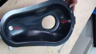
2 ASSEMBLY ISTRUCTIONS SQUAT WITH FRESH WATER FLUSH Prepare the base of bathroom. Drill the base into the marked zone (see photo on the left)

")


3 Insert pump in the base (attention of flow direction) Fix the pump with the screws. Assemble the flex tube A (short tube) in aspiration of pump.


4 Assemble one of flex tubes B (long tube) in expulsion of pump. Place the two tube in the corner of the base. Insert the squat in the base of bathroom. Attention that the two flex tube are not mashed.


5 Drill the squat in the signed point for insert the tank. N 3 Hole Ø30mm Assemble left wall. Fix the wall at base with rivets.


6 Assemble rear wall. Fix the wall at base and at the left wall with rivets Drill the walls and the squat and fixing with rivets.

 Hole")


7 Prepare the tank. Drill the tank in this point (only rear wall) Hole Ø100mm Insert and fix the cap in the front hole present into the tank.


8 Assemble this three components. Insert and fix this block in the rear hole present into the tank. Position the tank over the squat. Insert the pegs into the holes present on the squat.


9 Drill the rear wall and the rear of tank. Fix the tank at rear wall with rivets. ATTENTION : SEE UNDER PHOTO FOR MEASURE On the external of bathroom drill 4 hole Ø6mm. Drill the rear wall and the rear of tank. IMPORTANT : Drill upper the zone delimitated of black line

 at")


10 Assemble the tube B (short tube) at tank. Assemble this four components. ATTENTION AT FLOW OF NOT RETURN VALVE!
")
.")


11 Assemble the second flex tube B (long tube) at this block (see the position in the photo). Assemble flex tube B (long tube) coming from foot pump at this block (see the position in the photo).


12 Insert block of not return valve into the hole present in the tank. Insert the other side of flex tube in the hole present into the squat. On the left see the complete installation.


13 Assemble right wall. Fix the wall at base and at the rear wall with rivets. Drill the right wall and the rear of tank. Fix the tank at right wall with rivets. On the external of bathroom drill 4 hole Ø6mm. IMPORTANT : Drill upper the zone delimitated of black line.


")


14 Prepare the squat cap. Fix the right bracket with two rivet (see the photo) Fix the left bracket with two rivet (see the photo)


")
15 Insert one nozzle into the predisposed hole and fix with the ring. ATTENTION : insert the gasket before fixing. Insert other nozzle into the predisposed hole and fix with the ring. ATTENTION : insert the gasket before fixing. ATTENTION : check the flow direction of nozzles (see photo)


16 Assemble this four components. Insert this block in the nozzle positioned in head of the cap. Insert the curve connection in the nozzle positioned in tail of the cap.


17 Connect this two junctions with the flex tube. Prepare the paddle Assemble the paddle and counterweight with screw.


18 Insert the paddle into the hole of the brackets (insert at pression). Assemble the hinge at the cap with two rivets.


19 Fix the free tube at the connection of the cap, and position the cap into the squat. Drill the Squat and Fix the hinge with two rivet.


20 Complete the assembly with calibration of the hinge. Operate on the central screw of hinge is possible to regulate the angle required to open the cap for clean the squat. Close the cap and complete the bathroom assembly.
NOTE DI ASSEMBLAGGIO ASSEMBLY NOTE pag. 1/6 Y102 YAMAHA MT 09 Tracer 2015 KIT
 NOTE DI ASSEMBLAGGIO ASSEMBLY NOTE pag. 1/6 A C B D SMONTAGGIO DELLA PEDANA CENTRALE DI SERIE Svitare i due bulloni supporto cavalletto centrale, sul lato destro e sinistro della moto (Fig. A,B); Rimuovere
UNA. Istruzioni di montaggio / Installation instructions
 UNA Istruzioni di montaggio / Installation instructions UNA Istruzioni per il montaggio dei lavabi semincasso art. UNA75L e art. UNA90L Installation instructions of semi-inset basins art. UNA75L and art.
Istruzioni di montaggio per ECOFLEX KIT Assembling Instructions for ECOFLEX KIT
 Page 1/7 Release 2 ECOFLEX Kit Istruzioni di montaggio per ECOFLEX KIT Assembling Instructions for ECOFLEX KIT Prima di effettuare le varie operazioni procedere nel modo seguente: - Portare la macchina
Mounting the allocator on the heater. Montaggio del ripartitore sul radiatore
 Mounting the allocator on the heater Montaggio del ripartitore sul radiatore Allocator must be mounted at 66% (or 75% for HCA version 2 only or later versions) of the Height of the radiator and half of
MONTAGGIO DELL'ELEVATORE IDRAULICO DEL CONTENITORE
 Supporto tecnico Turbograss MONTAGGIO DELL'ELEVATORE IDRAULICO DEL CONTENITORE Rif. tuitb03 All. tav.19,16/95,1a 14/96, 1c Per la posizione e la procedura di montaggio dei particolari fare riferimento
HERMITAGE ISTRUZIONI DI MONTAGGIO ASSEMBLY INSTRUCTIONS
 U Via Monsignor Tenderini snc 01033 Civita Castellana (Vt) - Italy t. (+39) 0761 599499 f. (+39) 0761 514232 e. [email protected] w. WWW.RTCERM.IT E E1 G D1 D B D1 1 Girare la vasca sottosopra e fissare con
ASSEMBLY NOTE pag.1/6
 ASSEMBLY NOTE pag.1/6 A B Final body no CAT C D DISMOUNTING THE ORIGINAL Disassemble the original silencer (Fig. A), removing the screw of the crank (Fig.B) and loosening the small metal bracket, which
Assembly Instructions for kit NEW SOLUTION HOSE
 Page 1 / 7 Release 01 Kit code 909 5527 000 Assembly Instructions for kit NEW SOLUTION HOSE Prima di effettuare le varie operazioni procedere nel modo seguente: - portare la macchina su un terreno pianeggiante
NOTE DI ASSEMBLAGGIO ASSEMBLY NOTE pag. 1/6 H129 Honda CRF 250 R 2015 Kit
 NOTE DI ASSEMBLAGGIO ASSEMBLY NOTE pag. 1/6 A B SMONTAGGIO DEL SILENZIATORE ORIGINALE Svitare le viti della sella e delle fiancatine (Fig. A,B,C); Rimuovere la sella per poi rimuovere le fiancatine (Fig.
INSTALLAZIONE INSTALLATION
 INSTALLAZIONE INSTALLATION KIT SOFFIONI MySlim A CONTROSOFFITTO KIT MySlim SHOWER HEADS FOR FALSE CEILING Art. KIT00006 AVVERTENZE: L impianto deve essere effettuato da personale autorizzato, certificato
Replacement of hose carrier chain
 3 1. Bring the boom in horizontal position and make the extension completely retract. 2. Remove the rear panel. 3. Remove the front guard on the boom hood. 4. In case of machine with basket pre-arrangement,
NOTE DI ASSEMBLAGGIO ASSEMBLY NOTE pag. 1/5 H131 Honda CB 650 F 2014 KIT
 NOTE DI ASSEMBLAGGIO ASSEMBLY NOTE pag. 1/5 ATTENZIONE: Questo impianto di scarico, codice: H131090IV / H131090TV, è omologato per l utilizzo stradale SOLAMENTE con l istallazione del catalizzatore codice:
IM095.1 ISTRUZIONI DI MONTAGGIO ASSEMBLY DIAGRAM > LINK SYSTEM SOSPESO ED ELEMENTO TERMINALE APERTO > HANGING LINK SYSTEM AND OPEN END ELEMENT
 ISTRUZIONI DI MONTAGGIO > LINK SYSTEM SOSPESO ED ELEMENTO TERMINALE APERTO ASSEMBLY DIAGRAM > HANGING LINK SYSTEM AND OPEN END ELEMENT HANGING LINK SYSTEM AND OPEN END ELEMENT: Identificare la posizione
Pagina 2 di 9 A - OGGETTO A - OBJECT B - SCOPO B - SCOPE. Instruction Sheet Rev. A
 COMPARTMENT A - OBJECT Wired fuse and relay box for engine compartment (P/N 1745062). Base box supply with sealing and spacer rings assembled whereas cover is in kit into same packaging. Base box have
NOTE DI ASSEMBLAGGIO ASSEMBLY NOTE pag. 1/5 Y102 YAMAHA MT x1
 NOTE DI ASSEMBLAGGIO ASSEMBLY NOTE pag. 1/5 ATTENZIONE: Questo impianto di scarico, codice: Y102090CV / Y102090TV, è omologato per l utilizzo stradale, SOLAMENTE con l istallazione del catalizzatore, codice:
NOTE DI ASSEMBLAGGIO ASSEMBLY NOTE pag. 1/5 Y104 YAMAHA MT x1
 NOTE DI ASSEMBLAGGIO ASSEMBLY NOTE pag. 1/5 ATTENZIONE: Questo impianto di scarico, codice: Y104090CV / Y104090TV, è omologato per l utilizzo stradale, SOLAMENTE con l istallazione del catalizzatore, codice:
Istruzioni di montaggio per l ECOFLEX KIT Assembling Instructions for ECOFLEX KIT
 Page 1/7 Release 4 ECOFLEX SYSTEM Istruzioni di montaggio per l ECOFLEX KIT Assembling Instructions for ECOFLEX KIT Prima di effettuare le varie operazioni procedere nel modo seguente: - Portare la macchina
CP 22 E CP 22 EW tavola 1 view 1 B
 CP 22 CP 22 E CP 22 EW tavola 1 view 1 B2201.01 CP 22 E CP 22 EW tavola 1 - view 1 n. codice descrizione description n. codice descrizione description 1 0429 Contenitore schiumato mod.26 Bin with foamed
Heat cost allocators Mounting manual
 - heat cost allocators ripartitori di calore Mounting Manual Manuale di montaggio Heat cost allocators Mounting manual Ripartitori dei costi di calore - Manuale di montaggio pag. 1 Mounting the allocator
IM117.1 ISTRUZIONI DI MONTAGGIO ASSEMBLY DIAGRAM PANNELLATURA ORIZZONTALE SOTTO PONTI AD ANGOLO HORIZONTAL PANELS UNDER CORNER BRIDGING ARRANGEMENTS
 ISTRUZIONI DI MONTAGGIO PANNELLATURA ORIZZONTALE SOTTO PONTI AD ANGOLO ASSEMBLY DIAGRAM HORIZONTAL PANELS UNDER CORNER HORIZONTAL PANELS UNDER CORNER bussola / buch perno / pin piedino / adjustab le feet
ASSEMBLY NOTE / SCHEDA DI MONTAGGIO pag.1/9 D155 Ducati Panigale 1299 Coppia sil.
 ASSEMBLY NOTE / SCHEDA DI MONTAGGIO pag.1/9 D155 Ducati Panigale 1299 Coppia sil. 01 02 03 04 05 06 SMONTAGGIO IMPIANTO ORIGINALE Rimuovere le carene inferiori destra e sinistra della moto, svitando le
Spare parts
 TURBODRIVE 282 Spare parts 901.16940 Versions Description Date 901.16930 Emission: M. Gramegna 03/02/2009 901.16931 Modified drawings 14 15 17-22 and add drawings 16 03/03/2009 901.16932 Modified drawing
Heat cost allocators Mounting manual
 Heat cost allocators Mounting manual Ripartitori dei costi di calore - Manuale di montaggio pag. 1 Mounting the allocator on the heater Montaggio del ripartitore sul radiatore Allocator must be mounted
IM123.0 ISTRUZIONI DI MONTAGGIO ASSEMBLY DIAGRAM LETTO BED45 CON MECCANISMO: BED BED45 WITH MECHANISM:
 ISTRUZIONI DI MONTAGGIO LETTO BED45 CON MECCANISMO: ASSEMBLY DIAGRAM the holes on the perimeter of the bed, with the hole towards the LETTO BED45 CON MECCANISMO: boccola / axle box perno snodabile / articulated
GUARNIZIONI PRINCIPALI / KIT - MAIN GASKETS / SET
 GUARNIZIONI PRINCIPALI / KIT - MAIN GASKETS / SET MOTORE / ENGINE: 8210.01 Dati tecnici: / Technical data: N Cyl: 6 L Ø 135.00 mm Cilindrata/Capacity: 12883 cc Aspirato/Aspirated Montato su: / Fitting
Prefiltri Prefilter ISTRUZIONI PER L USO OPERATING INSTRUCTIONS
 Prefiltri Prefilter PF ISTRUZIONI PER L USO OPERATING INSTRUCTIONS 1.Componenti 1.Components DESCRIZIONE DESCRIPTION 1 Semi guscio inferiore Bottom spherical shell flange 2 Cestello Basket 3 Guarnizione
BUSSOLE CONICHE DI SERRAGGIO - DATI TECNICI TAPER BUSHES - THECNICAL DATA
 - DATI TECNICI - THECNICAL DATA Caratteristiche / Characteristics Le bussole coniche permettono di allineare o bloccare pulegge, pignoni dentati o giunti all albero di trasmissione in modo rapido e senza
MANUALE MONTAGGIO MOTORI SERIE VEGL MOTOR ASSEMBLY MANUAL VEGL SERIES
 MOTORI A CORRENTE CONTINUA GLEICHSTROMMOTOREN D.C. MOTORS S.r.l. Cap.Soc. 100.000 i.v. 36050 MONTORSO V. (VI) Italy REA 113113 Via Valchiampo, 14 Reg.imprese n.00170250245 tel. 0039 444 685505 r.a. Cod.Fisc.
ACCESSORIO RICIRCOLO SANITARIO ELETTRONICO
 ACCESSORIO RICIRCOLO SANITARIO ELETTRONICO DESCRIZIONE Il KIT di ricircolo per il modulo ACS 40 E viene fornito separatamente dal modulo, è composto da un circolatore, valvola a sfera /4 M, valvola di
Libretto uso e manutenzione. Owner s handbook. rev /07
 Libretto uso e manutenzione Owner s handbook Elenco componenti List of components ALBERTO SASSI S.p.A. www.sassi.it 2 ALBERTO SASSI S.p.A. www.sassi.it 3 ALBERTO SASSI S.p.A. www.sassi.it 4 Tabella riferimento
ISTRUZIONI DI MONTAGGIO SETTING UP INSTRUCTIONS
 calibe ISTRUZIONI DI MONTGGIO SETTING UP INSTRUCTIONS LUN LEK-FREE PER L'INSTLLTORE: TTENZIONE! Per un corretto montaggio seguire attentamente le seguenti indicazioni FOR THE INSTLLER: WRNING! For a correct
SOSTITUZIONE MOTORE LECOASPIRA (escluso modelli FAV) LECOASPIRA MOTOR REPLACEMENT (except FAV) 01/03/16 v.01
 LECOASPIRA MOTOR REPLACEMENT (except FAV) 01/03/16 v.01") SOSTITUZIONE MOTORE LECOASPIRA (escluso modelli FAV) LECOASPIRA MOTOR REPLACEMENT (except FAV) 01/03/16 v.01 OGGETTO DELLA PROCEDURA PROCEDURE OBJECT 2 Per tutti i Lecoaspira (esclusi i nuovi FAV20/30/50/70/80)
SOSTITUZIONE MOTORE LECOASPIRA (escluso modelli FAV) LECOASPIRA MOTOR REPLACEMENT (except FAV) 01/03/16 v.01 OGGETTO DELLA PROCEDURA PROCEDURE OBJECT 2 Per tutti i Lecoaspira (esclusi i nuovi FAV20/30/50/70/80)
SISTEMA COMPLETO DI ILLUMINAZIONE VANO LAMPADA A LED TIPO ILV24 s. COMPARTMENT SYSTEM LIGHTING COMPLETE LED LAMP TYPE ILV24 s
 SISTEMA COMPLETO DI ILLUMINAZIONE VANO LAMPADA A LED TIPO ILV24 s COMPARTMENT SYSTEM LIGHTING COMPLETE LED LAMP TYPE ILV24 s Caratteristiche generali Mean features Lampade a bassa tensione (24Vcc) Lamps
ART. 1254AL155SS CERNIERE PER PORTE A SPINGERE MANO SINISTRA / HINGES FOR LEFT-HAND DOORS
 SCHEDA INSTALLAZIONE / INSTALLATION SHEET ART. 1254AL155DS CERNIERE PER PORTE A SPINGERE MANO DESTRA / HINGES FOR RIGHT-HAND DOORS UPPER HINGE BODY SACCHETTO GRUPPO MOLLA / PLASTIC BAG WITH THE SPRING
SCHEMI DI MONTAGGIO ASSEMBLY DIAGRAM
 SCHEMI DI MONTAGGIO ASSEMBLY DIAGRAM Ver. 3.2 ISGI008 BIGAS INTERNATIONAL AUTOGAS SYSTEMS S.r.l. Sede e Stabilimento: Via di Le Prata, 62/66 50041 Calenzano Firenze ITALY Tel. 0554211275-0554201432 Fax
IM043.3 ISTRUZIONI DI MONTAGGIO ASSEMBLY DIAGRAM CABINE ARMADIO MONOPOLI
 ISTRUZIONI DI MONTAGGIO CABINE ARMADIO MONOPOLI > SCHEMA SEQUENZA DI MONTAGGIO Pag. 1 > STRUTTURA Pag. 2 > RIPIANI Pag. 5 > ANTE Pag. 6 ASSEMBLY DIAGRAM MONOPOLI WALK IN CLOSET > ASSEMBLY DIAGRAM Pag.
IM043.2 ISTRUZIONI DI MONTAGGIO ASSEMBLY DIAGRAM CABINE ARMADIO MONOPOLI
 ISTRUZIONI DI MONTAGGIO CABINE ARMADIO MONOPOLI > SCHEMA SEQUENZA DI MONTAGGIO Pag. 1 > STRUTTURA Pag. 2 > RIPIANI Pag. 5 > ANTE Pag. 6 ASSEMBLY DIAGRAM MONOPOLI WALK IN CLOSET > ASSEMBLY DIAGRAM Pag.
P/N DESCRIPTION QUANTITY
 BEFORE STARTING WORKING, PLEASE MAKE SURE THAT YOU GOT ALL THE BELOW COMPONENTS OLD PUMP NUMBER BHD2226 NEW PUMP BHD2238 AQND KIT DRE2570 CHECK S/N IT S IMPORTANT P/N DESCRIPTION QUANTITY BHD2238 or BHD2239
Technical Guidelines GON % Italian production. sports car oriented
 The rubber nozzle mod GON (Gas Oval Nozzle) has the intake with 210 mm x 105 mm dimensions and has been developed by WORKY in order to be more SPORTS CAR oriented. It has been studied for vehicles with
Accessori / Accessories
 Accessori / Accessories Raccordo a 4 Vie 4-way Junction Realizzato in acciaio verniciato con polveri termoindurenti, permette di raccordare quattro elementi della trave ad un solo punto Realized in thermosetting
BREVETTATO / PATENTED Meccanismo regolabile per armadi con ante scorrevoli sovrapposte (registrabile per ogni spessore di ante)
") BREVETTATO / PATENTED Meccanismo regolabile per armadi con ante scorrevoli sovrapposte (registrabile per ogni spessore di ante) Adjustable system for wardrobes with overlapping sliding doors (adjustable
BREVETTATO / PATENTED Meccanismo regolabile per armadi con ante scorrevoli sovrapposte (registrabile per ogni spessore di ante) Adjustable system for wardrobes with overlapping sliding doors (adjustable
KIT AMMORTIZZATORE DI STERZO
 KIT AMMORTIZZATORE DI STERZO Codice: KIT032 Marca: BUELL Modello: X1 LIGHTNING MATERIALE CONTENUTO NEL KIT - n 1 Attacco forcella d.54 - n 2 Vite Tcei M5x12 - n 1 Vite in ergal M8x25 - n 2 OR - n 1 Ammortizzatore
PROFILI ALLUMINIO ALUMINIUM PROFILES
 PROFILI ALLUMINIO ALUMINIUM PROFILES I PROFILI IN ALLUMINIO SCILM CONSENTONO LA REALIZZAZIONE DI OGNI TIPO DI STRUTTURA (TAVOLI, ARMADIATURE A GIORNO O CON ANTE, CARRELLI, PENSILI ECC.). Scilm aluminum
KRIPTOS 40 _FRAMELESS
 KRIPTOS 40 _FRAMELESS Kriptos 40 installato e completamente integrato nel cartongesso Kriptos 40 installed recessed into plaster ceiling 156_ ERREBILUCE KRIPTOS 40 _FRAMELESS La struttura di Kriptos 40
1CI90 1CI120 1CIA180 CANALI ATTREZZATI CHANNELS. Manuale d installazione e uso Installation and use manual
 1CI90 1CI120 1CIA180 CANALI ATTREZZATI CHANNELS Manuale d installazione e uso Installation and use manual Complimenti per aver acquistato una apparecchiatura Barazza! Questa è un apparecchiatura di grande
SACE Emax 2. 1 - Operazioni preliminari - Preliminary Operations. 2 - Verifica contenuto kit - Kit content verify C X8 B D X4.
 Doc. N 1SDH001399R0932 - L9679 SAE Emax 2 Guide Laterali Parte Mobile - E1.2 Lateral Guides Moving Part - E1.2 Seitenbleche - E1.2 Plaques Laterales - E1.2 Laterales - E1.2 1 - Operazioni preliminari -
SACE Emax Operazioni preliminari - Preliminary Operations. 2 - Verifica contenuto kit - Kit content verify 1 OK 2 OK
 Doc. N SDH00400R090 - ECN0000674 - Rev. B SACE Emax Kit Morsettiera - E.-E4.-E6. Kit Klemmleiste - E.-E4.-E6. Kit Terminal Box - E.-E4.-E6. Kit Bornier - E.-E4.-E6. Kit Regleta De Bornes - E.-E4.-E6. -
ISTRUZIONI PER IL MONTAGGIO DEL KIT SSD INSTRUCTIONS TO INSTALL THE KIT SSD
 Audya Series ISTRUZIONI PER IL MONTAGGIO DEL KIT SSD INSTRUCTIONS TO INSTALL THE KIT SSD ISTRUZIONI PER L APERTURA DI AUDYA (FIG. 1) 1. Svitare le 4 viti poste sul fondo 2. Svitare le 2 viti poste
ACCESSORI PER CANCELLI SCORREVOLI ACCESSORIES FOR SLIDING GATES.
 ACCESSORI PER CANCELLI SCORREVOLI www.facsrl.com FINTO FINTO Tutte le misure sono espresse in mm, ove non diversamente specificato. All measures are in mm, if any other measurement unit is not specified.
BASIC CASSETTA - TELAI - PLACCHE
 BASIC CASSETTA - TELAI - PLACCHE 21.18/20 21.18/20 14.24/20/1 21.25/20 BASIC Cassetta di scarico da incasso a tasto doppio con scarico parziale 3l, totale 6-9 l Il Serbatoio della cassetta in unico pezzo
Istruzioni di montaggio kit ricircolo. Recycle kit assembling instructions
 Page 1 of 18 Release 0 Recycle kit 909 5960 000 Istruzioni di montaggio kit ricircolo Prima di effettuare le varie operazioni procedere nel modo seguente: - portare l interruttore di avviamento in posizione
NOTE DI ASSEMBLAGGIO ASSEMBLY NOTE pag. 1/5 T009 TRIUMPH STREET TWIN 1 SIL.
 NOTE DI ASSEMBLAGGIO ASSEMBLY NOTE pag. 1/5 01 03 02 04 05 06 07 08 SMONTAGGIO DEL SILENZIATORE ORIGINALE Rimuovere il paracalore svitando la vite di sostegno (Fig. 01); Rimuovere la fascetta innesto silenziatore,